


Distributed by
Any reference to Raytheon or RTN in this manual should be interpreted as Raymarine. The names Raytheon and RTN are owned by the
Raytheon Company.

TOP EDGE BLEED
MASK FOR 2 COLOUR SEATALK LOGO
ST 30
DEPTH
Operation and
Installation

TOP EDGE BLEED
MASK FOR 2 COLOUR SEATALK LOGO
Nautech Limited, Anchorage Park, Portsmouth
P03 5TD, England
Telephone (0705) 693611. Fax (0705) 694642
ST30 Depth Operation and Installation Handbook
SHALLOW DEEP
MINIMUM OFFSET
DISPLAY

 Metres
DEPTH
Autohelm and SeaTalk are registered Trade Marks of Nautech Limited
Autohelms policy of continuous improvement and updating may change product specifications without prior notice
Copyright Nautech 1992

ST30 Depth Operation and Installation Handbook
Package Contents
The following items are included in the ST30 Depth package:
1.ST30 Depth instrument
2.Fixing studs (2 off)
3.Thumb nuts (2 off)
4.Fitting template
5.1m power cable
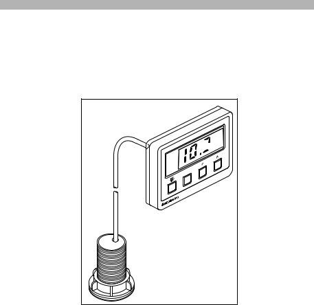
6.Depth transducer (through hull) with 10m cable and 1/8in spade connectors
7.Instrument cover
8.Operation and installation handbook
9.Daisy-chain cable
|
1 |
2 |
3 |
|
SHALLOW |
|
|
|
|
DEEP |
|
|
|
|
MINIMUM |
|
|
|
|
OFFSET |
|
|
|
|
DISPLAY |
|
|
|
6 |
|
|
|
|
|
DEPTH |
|
|
|
|
|
|
|
ST30 INSTRUMENT |
|
|
|
|
MOUNTING TEMPLATE |
|
TM |
7 |
|
4 |
|
SeaTalk |
|
|
2-HOLES |
1-HOLE |
|
|
DRILL 5mm |
||
|
|
DRILL 60.3mm |
||
|
|
|
( .197in ) DIA |
|
|
|
|
( 2,3/8in ) DIA |
|
|
|
|
|
|
|
|
|
|
SeaTalk |
TM |
8 |
|
5 |
9 |
ST30 |
|
|||
|
|
|
|
|
DEPTH |
|
|
|
|
Operation and |
|
|
|
|
Installation |
|
|
|
|
|
|
|
SeaTalk |
SeaTalk |
|
|
|
|
D624 |

ST30 Depth Operation and Installation Handbook |
3 |
|
Contents |
|
|
Introduction ....................................................................... |
4 |
|
Chapter 1: Control Head Installation ................................... |
5 |
|
1.1 |
Siting ............................................................................. |
5 |
1.2 |
Mounting procedure ........................................................ |
6 |
1.3 |
Power supply (Stand-alone operation) ............................... |
7 |
1.4 |
Power supply (SeaTalk system) ........................................ |
7 |
1.5 |
Connection to adjacent ST30 Instruments ......................... |
8 |
Chapter 2: Transducer Installation...................................... |
9 |
|
2.1 |
Connection to instrument ................................................. |
9 |
2.2 |
Transducer type ............................................................. |
9 |
2.3 |
Installation .................................................................... |
10 |
Chapter 3: Fault Finding................................................... |
12 |
|
Chapter 4: Maintenance................................................... |
13 |
|
4.1 |
Instrument .................................................................... |
13 |
4.2 |
Transducer ................................................................... |
13 |
4.3 |
Cabling ........................................................................ |
13 |
4.4 |
Advice .......................................................................... |
13 |
Chapter 5: Operation ....................................................... |
14 |
|
5.1 |
Display Key .................................................................. |
14 |
5.2 |
Light Key ...................................................................... |
16 |
5.3 |
Alarms ......................................................................... |
16 |
|
Loss of signal ............................................................... |
16 |
Chapter 6: Calibration ..................................................... |
17 |
|
6.1 |
Entry to calibration ........................................................ |
17 |
6.2 |
Depth units selection ..................................................... |
17 |
6.3 |
Alarms and Offset ......................................................... |
18 |
|
Shallow alarm ............................................................... |
18 |
|
Deep alarm .................................................................. |
19 |
|
Offset .......................................................................... |
20 |
|
Exit calibration .............................................................. |
21 |
6.4 |
Calibration Lock/Unlock ................................................ |
22 |
|
Return to normal display mode ...................................... |
23 |
6.5 |
Master/Repeater display ............................................... |
23 |
|
Return to normal display mode ...................................... |
25 |
Chapter 7: General Specification ...................................... |
26 |
|
4 |
ST30 Depth Operation and Installation Handbook |
|
|
|
|
Introduction
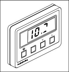
Designed for above or below deck installation, the ST30 Depth can be used as a stand-alone master instrument or be set up to repeat information from the SeaTalk bus.
The ST30 Depth will display the following information:
•Water depth
•Shallow alarm
•Deep alarm
•Keel/Waterline offset
•Minimum depth
•Illumination level
SHALLOW DEEP
MINIMUM OFFSET
DISPLAY

 Metres
DEPTH
TM
D625

Chapter 1: Control Head Installation |
5 |
|
|
|
|
Chapter 1: Control Head Installation
|
42mm |
|
110mm (4.33in) |
(1.65in) |
|
|
24mm (1.0in) |
|
SHALLOW |
(2.20in) |
(3.46in) |
DEEP |
||
MINIMUM |
||
OFFSET |
||
|
||
DISPLAY |
56mm |
88mm |
|
||
Autohelm |
DEPTH |
|
|
|
D626 |
1.1 Siting
The ST30 Depth instrument may be installed above or below deck where it is:
•easily readable by the helmsman (normally viewed at eye level)
•protected from physical damage
•at least 230mm (9in) from a compass
•at least 500mm (20in) from radio receiving equipment
•accessible from behind for ease of installation and cable running
Note: To prevent the build-up of moisture the instrument breathes through the back cover. The instrument must, therefore, be mounted where the back cover is protected from direct water.
The case is fitted with a foam gasket to form a water tight seal between the instrument and the installation face.
6 |
ST30 Depth Operation and Installation Handbook |
|
|
|
|
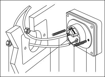
1.2 Mounting procedure
3 |
6 |
5 |
2 |
4 |
1 |
|
|
|
|
|
D627 |
1 Instrument 2 Fixing studs 3 Thumb nuts 4 Sealing gasket |
|
|
|
||
5 Power supply cable 6 Transducer cable
1.Make sure the surface to which the instrument (1) is to be mounted is smooth and flat.
2.Use the template (supplied) to mark the centres for the fixing studs (2) and the instrument connector boss.
Note: To allow protective covers to be fitted, adjacent instruments should be sited not less than 6mm (0.24in) from each other (116mm centre to centre min.).
3.Drill two 5mm (0.2in) diameter holes for the fixing studs (2).
4.Using a 60mm (2 3/8in) diameter cutter, drill a location hole for the instrument connector boss.
5.Connect the power supply and transducer cables to the back of the instrument (1). (See relevant installation sections)
6.Screw the two fixing studs (2) into the back cover of the instrument
(1).
7.Install the instrument (1) and secure with the thumb nuts (3) provided.

Chapter 1: Control Head Installation |
7 |
|
|
|
|
1.3 Power supply (Stand-alone operation)
Caution: The ST30 Depth must only be connected to a 12V supply.
+ |
+ |
|
SEATALK |
H
T
P
E
D
+ |
+ |
|
5A |
+ |
Red |
|
|
12V Supply |
|
– |
Screen |
|
D627a
For stand-alone operation, use the 1m cable supplied with the instrument.
1.Connect the moulded power plug to either SeaTalk connection on the rear of the instrument. Run the free end back to the vesselÕs distribution panel.
2.Cut the power cable to length and connect the red wire to the positive 12V terminal and the screen to 0V. Protect with a 5A circuit breaker or fuse.
1.4Power supply (SeaTalk system)
If the ST30 Depth is to be connected to a SeaTalk system, use a Standard SeaTalk Extension or Interface cable.
Autohelm |
Autohelm |
Autohelm |
|
Power |
|
|
|
|
Extension Cable |
D628 |
|
 Loading...