


 Loading...
DSM250
Digital Sounder
Module
Owner’s
Handbook
Document number: 81211_1
Date: December 2002
DSM250 Digital Sounder Module |
iii |
DSM250 Digital Sounder Module
Owner’s Handbook
December 2002
Intended Use
Raymarine DSM250 Digital Sounder Modules provide echo sounder data that can be displayed on Raymarine PLUS Radar, Chartplotter, or Fishfinder display units. DSM250 Digital Sounder Modules are intended for recreational depth finding and fishfinding purposes.
SAFETY NOTICES
This equipment must be installed and operated in accordance with the instructions contained in this manual. Failure to do so can result in personal injury and/or navigational inaccuracies. In particular:
HIGH VOLTAGE. The DSM250 contains high voltages. Adjustments require specialized service procedures and tools only available to qualified service technicians – there are no user serviceable parts or adjustments. The operator should never remove the cover or attempt to service the equipment.
CAUTION:
Removing the transducer cable from the rear of the DSM250 while the sounder module is powered on can cause sparks. Only remove the transducer cable after power has been removed from the DSM250. As with any electronic device, be sure the sounder module is mounted where it is well ventilated and free from gasoline fumes.
If the transducer cable is accidentally removed while the DSM250 is powered on, remove power from the sounder module, replace the transducer cable, and then return power to the module. As a safety feature, the DSM250 only recognizes that the transducer is connected at power-up.
iv |
DSM250 Digital Sounder Module |
EMC Conformance
All Raymarine equipment and accessories are designed to the best industry standards for use in the recreational marine environment.
The design and manufacture of Raymarine equipment and accessories conform to the appropriate Electromagnetic Compatibility (EMC) standards, but correct installation is required to ensure that performance is not compromised.
Preface
This handbook describes the Raymarine DSM250 Digital
Sounder Module (200/50 kHz).
This device must be connected to an hsb2 PLUS Radar, Chartplotter, or Fishfinder display unit to show echo sounder data. The DSM250 will not work with older HSB (non-PLUS) displays.
Note: Older HSB (non-PLUS) display units must be upgraded to hsb2 before they can function with the DSM250.
Echo sounder systems require an appropriate Raymarine transducer unit and inter-connecting cable. Details for selecting and installing the transducer are described in document number
81196, Transducers for Fishfinders Owner’s Handbook.
This handbook contains very important information on the installation and operation of your new equipment. In order to obtain the best results in operation and performance, please read this handbook thoroughly.
Raymarine’s Technical Services representatives or your local dealer will be available to answer any questions you may have.
Conventions
Raymarine echo sounding (sonar) devices with integrated displays are known as Fishfinders. In this document, the DSM250— which does not have its own display—is alternatively called a Digital Sounder Module, Sounder, or just Module. The DSM250’s image data can be viewed on a display unit when that display is in Sonar Mode.
DSM250 Digital Sounder Module |
v |
Throughout this handbook, the dedicated (labelled) keys are shown in bold capitals; for example, MENU. The soft key functions, menu names and options are shown in normal capitals; for example, SCREEN.
Operating procedures, which may consist of a single key-press or a sequence of numbered steps, are indicated by a symbol in the margin. When the procedure requires you to press a soft key, the soft key icon is shown in the margin.
Technical Accuracy
The technical and graphical information contained in this handbook, to the best of our knowledge, was correct as it went to press. However, the Raymarine policy of continuous improvement and updating may change product specifications without prior notice. As a result, unavoidable differences between the product and handbook may occur from time to time, for which liability cannot be accepted by Raymarine.
Warranty
To register your DSM250 Digital Sounder Module ownership, please take a few minutes to fill out the warranty registration card found at the end of this handbook. It is very important that you complete the owner information and return the card to the factory in order to receive full warranty benefits.
Raymarine Products and Services
Raymarine products are supported by a network of Authorized Service Representatives. For information on Raymarine products and services, contact either of the following:
United States Raymarine, Inc.
22 Cotton Road, Unit D
Nashua, NH 03063-4219
USA
Telephone:1-603-881-5200
1-800-539-5539
Fax: 1-603-864-4756
vi |
|
DSM250 Digital Sounder Module |
Europe |
Raymarine Ltd |
|
|
Anchorage Park |
|
|
Portsmouth, Hampshire |
|
|
England PO3 5TD |
|
|
Telephone: +44 (0) 23 9269 3611 |
|
|
Fax: |
+44 (0) 23 9269 4642 |
Or, you may contact us on the World Wide Web at:
www.raymarine.com
This product contains technology provided under license by Acorn Group plc. The copyright of this intellectual property is acknowledged by Raymarine, Inc. as are Acorn’s trademarks and patents. Acorn’s world wide web address is www.acorn.com.
Raymarine is a registered trademark of Raymarine Limited. SeaTalk is a registered trademark of Raymarine Limited. hsb2 is a trademark of Raymarine Limited.
Pathfinder PLUS is a trademark of Raymarine Limited.
© Raymarine, Inc. 2002

DSM250 Digital Sounder Module vii
Contents
|
|
SAFETY NOTICES ........................................................ |
iii |
|
|
EMC Conformance .......................................................... |
iv |
|
|
Warranty ............................................................................ |
v |
|
|
Raymarine Products and Services ..................................... |
v |
Chapter 1: |
Overview .................................................................. |
1-1 |
|
|
1.1 |
Introduction .......................................................... |
1-1 |
|
|
How to Use This Handbook ........................................... |
1-2 |
|
|
What's New .................................................................... |
1-3 |
|
|
General ........................................................................... |
1-4 |
|
|
Sonar Mode Display Features ........................................ |
1-5 |
|
1.2 |
Sonar Mode Display ............................................. |
1-5 |
|
|
Operating Modes ........................................................... |
1-7 |
|
|
Sonar Options ................................................................ |
1-8 |
|
|
Sounder Functions ......................................................... |
1-9 |
Chapter 2: |
Installation .............................................................. |
2-1 |
|
|
2.1 |
Introduction .......................................................... |
2-1 |
|
|
Planning the Installation ................................................ |
2-2 |
|
|
EMC Installation Guidelines ......................................... |
2-2 |
|
2.2 |
Unpacking and Inspecting the Components ......... |
2-4 |
|
2.3 |
Selecting the Equipment Location ........................ |
2-4 |
|
|
Sounder Module Mounting Location ............................ |
2-4 |
|
2.4 |
Cable Runs ............................................................ |
2-5 |
|
2.5 |
Mounting the Sounder Module ............................. |
2-8 |
|
2.6 |
System Connections ............................................. |
2-9 |
|
|
DC Power Connection ................................................. |
2-10 |
|
|
Ground Connection ...................................................... |
2-11 |
|
|
hsb2 Connection ............................................................ |
2-12 |
|
|
Transducer Connection ................................................ |
2-13 |
viii |
|
DSM250 Digital Sounder Module |
|
|
|
EMC Conformance ...................................................... |
2-15 |
Chapter 3: |
Getting Started ....................................................... |
3-1 |
|
|
3.1 |
Introduction ........................................................... |
3-1 |
|
3.2 |
Powering on the Sounder Module ......................... |
3-1 |
|
|
Status LED ..................................................................... |
3-1 |
|
3.3 |
Updating Software on the Display Unit ................ |
3-2 |
|
3.4 |
Selecting Repeater Mode ...................................... |
3-2 |
|
3.5 |
Selecting Sonar Mode ........................................... |
3-3 |
|
3.6 |
Simulator Mode ..................................................... |
3-5 |
|
|
Viewing Simulator Data ................................................. |
3-6 |
Chapter 4: |
System Setup ........................................................... |
4-1 |
|
|
4.1 |
Introduction ........................................................... |
4-1 |
|
4.2 |
Changing the Set Up Parameters ........................... |
4-1 |
|
4.3 |
System Set Up Parameters .................................... |
4-3 |
|
|
Data Boxes ..................................................................... |
4-5 |
|
|
Bearing Mode ................................................................. |
4-6 |
|
|
Cursor Reference ........................................................... |
4-6 |
|
|
Cursor Readout .............................................................. |
4-6 |
|
|
Day/Night ...................................................................... |
4-6 |
|
|
Help ................................................................................ |
4-7 |
|
|
Soft Keys ........................................................................ |
4-7 |
|
|
Key Beep ........................................................................ |
4-7 |
|
|
MOB Data ...................................................................... |
4-7 |
|
|
Autopilot Pop Up ........................................................... |
4-7 |
|
|
Menu Timeout Period .................................................... |
4-7 |
|
|
Units ............................................................................... |
4-8 |
|
|
Variation Source ............................................................. |
4-8 |
|
|
Bridge NMEA Heading ................................................. |
4-9 |
|
|
NMEA-Out Set Up ........................................................ |
4-9 |
|
|
Cursor Echo ................................................................. |
4-11 |
DSM250 Digital Sounder Module |
ix |
|
|
Date and Time Settings ................................................ |
4-11 |
|
GPS SOG/COG Filter .................................................. |
4-12 |
|
Compass Set Up ........................................................... |
4-12 |
|
Language ...................................................................... |
4-12 |
|
Simulator ...................................................................... |
4-12 |
4.4 Sonar Set Up Parameters ..................................... |
4-13 |
|
|
Target Depth ID ............................................................ |
4-14 |
|
Color Bar ...................................................................... |
4-14 |
|
Depth Digit Size ........................................................... |
4-14 |
|
Sonar HSB Mode ......................................................... |
4-14 |
|
Depth Offset ................................................................. |
4-15 |
|
Speed Calibrate ............................................................ |
4-16 |
|
Temperature Calibrate ................................................. |
4-16 |
|
Sonar History ............................................................... |
4-16 |
|
Sonar Interference Rejection ....................................... |
4-16 |
|
Sonar Simulator ........................................................... |
4-17 |
|
Version/Serial Numbers ............................................... |
4-17 |
Chapter 5: Basic Display Controls ............................................ |
5-1 |
|
5.1 |
Introduction .......................................................... |
5-1 |
|
Simulator ........................................................................ |
5-1 |
5.2 Setting Color and Brightness ................................ |
5-1 |
|
|
Lighting and Contrast (Monochrome Displays) ............ |
5-1 |
|
Brightness and Color Settings (Color Displays) ............ |
5-2 |
5.3 |
Controlling the Display ......................................... |
5-5 |
|
Selecting the Display Mode ........................................... |
5-6 |
|
Switching Between Sounder and Other Modes ........... |
5-12 |
5.4 |
Display Control Functions .................................. |
5-13 |
|
Viewing Data Boxes .................................................... |
5-14 |
|
Changing the Scroll Speed ........................................... |
5-14 |
|
Selecting the Power Setting ......................................... |
5-15 |
|
Changing the Sounder Range ...................................... |
5-16 |
|
Selecting the Frequency ............................................... |
5-19 |
|
Using Bottom Lock ...................................................... |
5-20 |
|
Using A-Scope ............................................................. |
5-22 |
x |
DSM250 Digital Sounder Module |
|
|
Using Zoom ................................................................. |
5-24 |
Chapter 6: Sonar Mode Operation ........................................... |
6-1 |
|
6.1 |
Introduction ........................................................... |
6-1 |
6.2 |
Interpreting and Adjusting the Sounder Image ..... |
6-1 |
|
Fish Indications .............................................................. |
6-2 |
|
Bottom Indications ......................................................... |
6-3 |
|
Using White Line ........................................................... |
6-5 |
|
Adjusting Display Gain (Sensitivity) ............................. |
6-5 |
|
Using Alarms ................................................................. |
6-8 |
6.3 |
Using VRM to Determine Depth & Distance from |
|
|
Vessel ................................................................... |
6-10 |
6.4 |
Waypoints ............................................................ |
6-12 |
|
Placing a Waypoint ...................................................... |
6-13 |
6.5 |
MOB .................................................................... |
6-14 |
Chapter 7: Maintenance and Problem Solving ...................... |
7-1 |
|
7.1 |
Maintenance .......................................................... |
7-1 |
|
Routine Checks .............................................................. |
7-1 |
|
Cleaning Instructions ..................................................... |
7-1 |
|
EMC Servicing and Safety Guidelines .......................... |
7-2 |
7.2 |
Resetting the System ............................................. |
7-3 |
7.3 |
Problem Solving .................................................... |
7-4 |
|
Status LED ..................................................................... |
7-6 |
|
How to Contact Raymarine ............................................ |
7-7 |
|
Worldwide Support ...................................................... |
7-10 |
Appendix: Specifications ........................................................ |
A-1 |
Chapter 1: Overview |
1-1 |
Chapter 1: Overview
1.1 Introduction
This handbook describes the DSM250 Digital Sounder Module. The DSM250 receives sonar signals from a transducer mounted in the water and transmits data via hsb2 to a Pathfinder PLUS Radar or Chartplotter display unit already installed in your vessel, eliminating the need for a separate display unit. You may also connect the module to an existing PLUS Fishfinder display for improved performance.
Note: Older HSB (non-PLUS) display units must be upgraded to hsb2 before they can function with the DSM250.
|
1 |
59- |
|
D61 |
|
Figure 1-1: DSM250 Digital Sounder Module
The DSM250 employs a very high transmission repetition or “ping” rate which, along with the digital adaptive high sample rate receiver, ensures that fish and bottom structure are presented in superb detail and optimal color allocation (in color LCD displays). The DSM250 digital bandwidth adaptation adjusts the receiver band width dynamically from very wide to very narrow, as required by the actual water conditions. This provides superior fish and bottom detection in conditions where other fishfinders see very little or nothing at all.
1-2 |
DSM250 Digital Sounder Module |
The DSM250 features dual frequency (200 kHz and 50 kHz) operation and—depending on the transducer installed and condi- tions—up to 1000 watts RMS output power and performance from 3 ft (1m) up to 5000 ft (1700 m).
This handbook describes DSM250 functions and how to use hsb2 PLUS Radar, Chartplotter, or Fishfinder display unit controls to operate sonar operations. Controls that are specific to either Radar, Chartplotter, or Fishfinder display unit functions are not described in this document but can be found in the handbook for that display.
Note: Many illustrations in this handbook show example screens. The screen you see on your display depends on your system configuration and set up options, so it may differ from the illustration.
How to Use This Handbook
If you are installing the DSM250 yourself, you should read
Chapter 2 before you start the installation.
For an overview of the display unit controls, read Chapter 5.
Chapter 3 will help you start using your system.
For detailed information on sounder module operations, refer to
Chapter 6.
To change the system set up default settings, read Chapter 4.
Chapter 1 gives an overview of the display unit controls and sonar operation.
Chapter 2 provides planning considerations and detailed instructions for installing the DSM250 and connecting the unit to the display unit via hsb2.
Chapter 3 provides instructions for setting up your system to suit your preferences. You should read this chapter to determine how to change the sonar system from the default settings.
Chapter 4 shows how to start using the display and viewing sonar echo data.
Chapter 5 details operating the display unit’s controls in Sonar mode.
Chapter 1: Overview |
1-3 |
Chapters 6 provides detailed information for operating the sonar functions - selecting depth range limits, adjusting gain, color and STC, setting alarms, using the VRM marker, marks and man overboard.
Chapter 7 provides information on user maintenance, and what to do if you experience problems.
The Appendix lists the technical specifications for the DSM250.
What's New
The DSM250 operates much like traditional Raymarine fishfinders. If you are already familiar with our displays, you won’t have much difficulty using the DSM250. Below is a list of DSM250 features that differ from our traditional fishfinder displays.
•No integral display. You connect the DSM250 to an hsb2 PLUS Radar, Chartplotter, or Fishfinder display unit to show echo sounder data.
•Digital sonar. The DSM250 employs a digital dynamic adaptive receiver and transmitter for dramatically improved fish and bottom detection in any water conditions.
•New automatic Gain modes. These automatic modes make the gain adjustments for you, based on depth and water conditions. The DSM250 provides three pre-defined automatic gain settings for Cruising, Trolling, and Fishing. See Adjusting Display Gain (Sensitivity) on page 6-5.
•Bottom hunt feature. The DSM250 features a digital “Hunt mode” that automatically searches for the bottom when the sounder is in Auto Range. Unlike our fishfinder displays, the DSM250 stays in manual range when placed there—it does not switch to auto mode by itself. When you are trying to automatically find bottom, you need to have the sounder module set to Auto Range mode. Refer to Hunt Mode on page 5-18.
•Auto frequency. When set to Auto Frequency, the DSM250 also alternates frequencies when hunting for bottom. If set for Manual frequency, the unit does not switch frequencies when bottom hunting. This differs from traditional Raymarine fishfinder displays. Details are found in Selecting the Frequency on page 5-19.
•New Auto STC mode. You can now let the sounder unit automatically choose the optimal STC level for reducing background noise that often appears in shallow water. See STC on page 6-8.
1-4 |
DSM250 Digital Sounder Module |
•Transducer detection. For safety reasons, if the transducer is disconnected and then reconnected while the sounder is powered on, the DSM250 does not detect that the transducer has been reattached. In this case, you must power down the DSM250, reconnect the transducer cable, and then power the sounder module back on before it operates properly.
•Status LED. The LED on the connector panel provides valuable status information. The LED blinks green while the module is operating normally. If the unit detects a problem, the LED blinks amber to indicate a warning or red for an error. The number of times the LED blinks is a code representing the nature of the problem. Refer to Status LED on page 7-6.
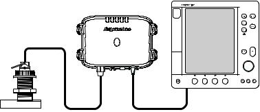
General
The DSM250 system, illustrated below, is comprised of the Digital Sounder Module, an hsb2 PLUS Radar, Chartplotter, or Fishfinder display unit, transducer, and associated cables.
hsb2 PLUS Display Unit
Digital Sounder Module
D6160-1
|
|
Transducer |
hsb2 |
Figure 1-2: Basic Echosounder System using the DSM250
The DSM250 module is waterproof to CFR46 and can be installed either above or below deck.
The unit includes connections to:
•power
•the transducer
•the display unit, via hsb2
•ground
Chapter 1: Overview |
1-5 |
Transducer
The DSM250 requires a transducer, mounted either thru-hull, inhull, or on the transom.
Transducers can measure water depth, and if so equipped, temperature, distance traveled, and/or speed. It is important to position your transducer correctly. For details on transducers, including location and installation instructions, see document number 81196, Transducers for Fishfinders Owner’s Handbook.
Note: If speed, temperature, or distance travelled are being input to the display unit via SeaTalk, the SeaTalk value is displayed instead of the value transmitted by the DSM250.
Sonar Mode Display Features
When connected to a display unit and switched to Sonar mode, the following data can be viewed:
•Depth, speed, and temperature, if the transducer is so equipped
•Single or split frequency sonar display – 50 kHz, 200 kHz
•Display options – sonar window, zoom, bottom lock, and A- Scope
•Horizontal and vertical half-screen windows to display additional data. Position data requires GPS.
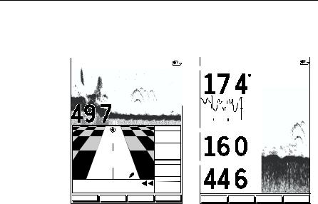
1.2Sonar Mode Display
When you first switch the display unit into Sonar mode, the scrolling bottom graph is displayed. This is a graphical representation of the echoes seen by the DSM250. As time passes, this display scrolls from right to left and becomes a record of the echoes seen. A typical display is shown in Figure 1-3 .
The images at the right hand side of the display are the most recent echoes. Some echoes indicate fish, and others show the bottom. It can also indicate bottom structures, such as a reef or shipwreck. The upper and lower depth range limits are shown.
The sonar screen includes a status bar that displays transducer frequency and indicates which auto settings are enabled (Gain, Color Gain, Range, Zoom and Frequency), and alarm status (fish and shallow/deep water depths).

1-6 |
DSM250 Digital Sounder Module |
You can customize the sounder by choosing what is displayed and how it is displayed (including language and units). For example, you can set the scroll speed of the bottom graph display, and you can select the range to adjust the depth displayed.
You can view the cursor position and a variety of data (such as speed and depth) from the transducer and other equipment in userselectable data boxes. These data boxes can be moved around the screen and they can be switched on or off.
Chapter 3 includes details on adjusting the display, other set up options are described in Section 4.4.
|
Power |
|
Target Depth ID On |
|
Auto |
Frequency |
|
Frequency |
|
Zoom |
|
|||
Mode |
|
|
||
Range |
Alarm enabled |
|
||
Indicators |
Alarm |
|||
Color gain |
Shallow, Deep |
|||
|
Indicators |
|||
|
Gain |
Fish |
||
|
|
|||
|
AUTO GCRZFH |
50kHz SD |
|
|
|
|
0 |
Water surface |
Cursor,
controlled
by trackpad
18
22 |
|
|
|
20 |
|
|
|
|
Depth markers |
|
|
|
|
|
|
|
|||||
|
|
|
|
|
|
|
|
|
|
|
|
|
|
|
32 |
|
|
|
|
|
|
|
35 |
33 |
|
|
|
|
|
|
Target image (fish arch) |
|
|
|
|
|
|
|
|||||
|
|
|
|
|
|
|
|
|||
|
36 |
37 |
|
|
|
|
|
|
||
38 |
36 |
|
|
|
|
|
|
|
|
|
42 |
|
|
40 |
|
|
|
|
Target image depth |
||
|
|
|
|
|
|
|
||||
|
|
|
|
|
|
|
|
|
||
|
|
|
|
|
|
|
|
|
|
|
Bottom depth 
|
|
|
ft |
60 |
|
Range |
|
|
|
|
|||
|
|
|
FREQUENCY ZOOM BTM.LOCK A-SCOPE
D6181-1
Figure 1-3: Typical Display in Sonar Mode

Chapter 1: Overview |
1-7 |
Operating Modes
Depending on the types of display(s) you have connected via hsb2, up to four full-screen modes – sonar, chart, radar, and data log are available. You select the operating mode using the DISPLAY key as described in Chapter 3.
You can also set Windows On to split the display into two halfscreen windows (horizontal or vertical) to show supplementary data, or to display sonar and chart or radar simultaneously.
Horizontal Half -Screen Window Options
Using horizontal half screens, the main operating mode is displayed in the upper window; you choose what is displayed in the lower window. The following information, if available on your system, can be shown:
Table 1-1: Horizontal Half-Screen Window Options
Full-screen |
|
mode |
Horizontal Half-Screen Window Options |
|
|
Sonar Mode |
Course Deviation Indicator (CDI), Bearing and Distance |
|
Indicator (BDI), Depth/Temp graph, Chart plotter, Radar |
|
|
Chart Mode |
CDI, BDI, Navigation Data (databoxes), Radar, Sonar |
|
|
Radar Mode |
CDI, BDI, Navigation Data, Chartplotter, Sonar |
|
|
Data Log Mode |
Half-screens not available |
|
|
Vertical Half -Screen Window Options
This option splits the sounder vertically. The left hand window displays data boxes; there are three different sets of data (A, B, and C) that you can select for display. The following information is available only in Sonar Mode:
Table 1-2: Vertical Half-Screen Window Options
Full-screen |
Vertical Half-Screen Window Options |
mode |
|
|
|
A |
Temperature, Speed, Depth |
|
|
B |
Position (latitude and longitude), Course Over Ground |
|
(COG), Speed Over Ground (SOG), Depth |
|
|
C |
Waypoint Range and Bearing, COG, SOG, Depth |
|
|
1-8 DSM250 Digital Sounder Module
Note: Receiving and displaying position data requires that a GPS is connected to your Raymarine system.
Horizontal Half-Screen |
|
|
|
Vertical Half-Screen |
|
|
|
||||||||
AUTO GCRZFH 50kHz |
|
|
|
|
AUTO GC FH |
50kHz |
|
|
|
||||||
|
|
|
|
0 |
|
TEMPERATURE |
|
0 |
|||||||
|
|
|
|
|
|
|
|
|
|
||||||
|
|
|
|
20 |
|
|
|
|
|
|
F |
|
|
|
|
|
|
|
|
|
|
|
|
|
|
|
|
|
|
||
|
|
|
|
|
|
|
|
|
|
|
|
|
|
|
|
|
|
|
|
|
|
|
|
|
|
|
|
|
|
|
|
|
|
|
|
|
|
|
|
|
|
|
20.1 |
|
|
|
|
|
|
|
|
40 |
|
|
|
|
|
|
15.1 |
|
20 |
|
|
|
|
|
|
|
|
|
|
|
|
|
|
|
|||
|
|
|
|
|
|
|
|
|
|
|
|
|
|
||
|
|
|
ft |
60 |
|
|
|
|
10.1 |
|
|
|
|
||
|
|
|
|
30 MINUTES |
0 |
|
|
|
|
||||||
|
|
|
|
XTE |
|
SPEED |
|
|
|
|
|
||||
|
|
|
|
|
|
|
|
|
|
|
|
|
|||
|
|
|
|
0.28nm |
|
|
|
|
|
|
|
|
|
||
|
|
|
|
|
|
|
|
|
|
|
|
|
|||
|
|
|
|
WPT BRG |
|
|
|
|
|
|
|
|
|
||
|
|
|
|
351°T |
|
|
|
|
kts |
|
40 |
|
|
||
|
|
|
|
|
|
|
|
|
|
|
|||||
|
|
|
|
WPT RNG |
|
|
|
|
|
|
|
|
|
||
|
|
|
|
|
DEPTH |
|
|
|
|
|
|||||
|
|
|
|
26.8nm |
|
|
|
|
|
|
|
|
|
||
|
STEER PORT |
TTG |
|
|
|
|
|
|
|
|
|
||||
|
03h:59m |
|
|
|
|
|
|
|
|
|
|||||
WAYPOINT 001 |
|
|
|
|
ft |
|
60 |
||||||||
|
|
|
|
|
|||||||||||
|
|
|
|
|
|
|
|
|
|||||||
FREQUENCY |
ZOOM |
BTM.LOCK |
A-SCOPE |
FREQUENCY |
ZOOM |
BTM.LOCK |
A-SCOPE |
D6206-1
Figure 1-4: Half-Screen Windows in Sonar Mode
Details on selecting windows are given in Chapter 3.
For details on the radar, chartplotter or fishfinder display, please refer to the Owner’s Handbook supplied with that unit.
Sonar Options
The DSM250 provides controls to select additional modes:
•Frequency – you can select the transducer frequency: 50 kHz for wide coverage and deep water, 200 kHz for a detailed view, both frequencies simultaneously or auto-frequency. The default setting is auto-frequency, which determines the optimum frequency of operation based on the current depth.
•Bottom Lock – changes the operating mode to re-set the bottom. It provides a bottom-up view: the bottom is used as the reference, its image is flattened and depths are displayed here.
Bottom lock mode is used primarily to filter out the bottom structure and display fish details only.
•A-Scope – displays a real-time image of the bottom structure and fish directly below the transducer. The A-Scope window also displays the patented Bottom Coverage width indication.
Chapter 1: Overview |
1-9 |
•Zoom – enlarges all or part of the bottom graph display. You can select x2, x4, or x6 magnification and the zoom area can be automatically or manually adjusted.
You can select the Zoom or Bottom Lock image to be displayed in place of the regular bottom graph display. Alternatively, you can set the display window to be split vertically with the bottom graph displayed in the right hand screen and the Zoom or Bottom Lock image displayed in the left hand screen. See Figure 1-5 .
If you choose dual frequency, the scrolling bottom graph is displayed in both frequencies, split horizontally. Zoom, Bottom Lock, or A-Scope can be displayed with the dual frequency graph.
All of these options are available when the sonar data is displayed in a half-screen window.
Sounder Functions
The DSM250 includes the following functions:
•Automatic or manual selection of scroll speed for bottom graph display
•Automatic or manual selection of transducer frequency
•Automatic or manual selection of depth range limits
•Automatic or manual selection of Gain, Color Gain, and STC settings
•Set up alarms for Fish, Shallow water and Deep water
•VRM marker to determine depth and distance
Operation of these functions is described in Chapter 3 and
Chapter 6.

1-10 |
|
|
|
DSM250 Digital Sounder Module |
|||
|
|
|
|
|
|
|
|
|
AUTO GC Z H SPLIT |
|
AUTO GC Z H SPLIT |
||||
0 |
0 |
|
|||||
20 |
|
|
20 |
|
|
||
|
|
|
|||||
40 |
40 |
60 |
60 |
200kHz |
80 |
|
200kHz |
80 |
6.8 |
|||
|
||||||||
50kHz |
0 |
|
50kHz |
0 |
|
|||
|
20 |
|
|
|
20 |
|
|
|
|
|
|
|
|
|
|||
|
40 |
|
|
|
40 |
|
|
|
|
|
|
|
|
|
|
||
|
60 |
|
|
|
60 |
|
|
|
|
|
|
|
|
|
|
||
|
|
|
|
|
|
|
||
ft |
80 |
ft |
80 |
27.2 |
FREQUENCY |
|
ZOOM |
|
BTM.LOCK |
|
A-SCOPE |
|
FREQUENCY |
|
ZOOM |
|
BTM.LOCK |
|
A-SCOPE |
Split Frequency
AUTO GC Z H 200kHz
0
30
20
20
40
10
0 60
BL
|
ft |
80 |
|
FREQUENCY ZOOM BTM.LOCK A-SCOPE
Bottom Lock Split with Bottom Graph
Split Frequency with A-Scope
AUTO GC Z H |
SPLIT |
|
|
|
|
|
||
|
|
|
55 |
0 |
||||
|
|
|
|
20 |
|
|
|
|
|
|
|
|
|
|
|
||
|
|
|
|
40 |
|
|
|
|
|
|
|
|
|
|
|
|
|
200kHz |
75 |
60 |
|
|
|
|
||
|
|
|
||||||
80 |
||||||||
50kHz |
55 |
0 |
||||||
|
|
|
|
20 |
|
|
|
|
|
|
|
|
|
||||
X4 |
|
40 |
|
|
|
|
||
|
|
|
|
|||||
|
|
|
|
|
|
|||
|
|
|
|
60 |
|
|
|
|
|
|
|
|
|
|
|
||
|
|
|
ft 75 |
80 |
||||
|
|
|
||||||
|
|
|
||||||
FREQUENCY ZOOM BTM.LOCK A-SCOPE
D6202-1
Zoom Split with Split Frequency
Figure 1-5: Sonar Display Options
Chapter 2: Installation |
2-1 |
Chapter 2: Installation
2.1 Introduction
This chapter provides installation instructions for your DSM250. Basic systems, such as that in Figure 2-1 below, are explained. Details for mounting the DSM250 and connecting the equipment are included.
Digital Sounder Module |
hsb2 PLUS Display Unit |
|
|
|
|
|
Junction |
|
Box |
|
SeaTalk |
Transducer |
Distribution Panel |
hsb2 |
Compass
12/24V Supply |
|
|
NMEA |
12/24V Supply |
|
|
12V Supply |
12V Supply |
GPS
D6164-1
Figure 2-1: DSM250 in an Integrated System
Note: If you wish to practice using the unit before installation, connect the HSB cable to a PLUS display unit and use the simulator mode as described in Chapter 3. For power, connect a 12V or 24V DC power supply, attaching the red wire via a quick blow 8A fuse to positive and the black wire to negative. See Section 3.6 for details.
For the system to display depth, water temperature and speed, you must install the transducer type(s) capable of transmitting the appropriate data.
For full functionality of the radar and chartplotter you need to provide position and heading data. For details, refer to the handbooks for those products.
2-2 |
DSM250 Digital Sounder Module |
Planning the Installation
Before you install your system, plan the installation, considering:
•Correct transducer for your application. See document number 81196, Transducers for Fishfinders Owner’s Handbook.
•Location of the display unit, as described in Section 2.3
•Cable Runs, including cables for an integrated system (to provide heading and position data, etc.), as described in Section 2.4.
EMC Installation Guidelines
All Raymarine equipment and accessories are designed to the best industry standards for use in the recreational marine environment.
Their design and manufacture conforms to the appropriate Electromagnetic Compatibility (EMC) standards, but correct installation is required to ensure that performance is not compromised.
Although every effort has been taken to ensure that they will perform under all conditions, it is important to understand what factors could affect the operation of the product.
The guidelines given here describe the conditions for optimum EMC performance, but it is recognized that it may not be possible to meet all of these conditions in all situations. To ensure the best possible conditions for EMC performance within the constraints imposed by any location, always ensure the maximum separation possible between different items of electrical equipment.
For optimum EMC performance, it is recommended that wherever possible:
•Raymarine equipment and cables connected to it are:
•At least 3 ft (1 m) from any equipment transmitting or cables carrying radio signals, e.g., VHF radios, cables and antennas. In the case of SSB radios, the distance should be increased to 7 ft (2 m).
•More than 7 ft (2 m) from the path of a radar beam. A radar beam can normally be assumed to spread 20 degrees above and below the radiating element.
•The equipment is supplied from a separate battery from that used for engine start. Voltage drops below 10 V and starter motor transients can cause the equipment to reset.
Chapter 2: Installation |
2-3 |
This will not damage the equipment, but may cause the loss of some information and may change the operating mode.
•Raymarine specified cables are used. Cutting and rejoining these cables can compromise EMC performance and must be avoided unless doing so is detailed in the installation manual.
•If a suppression ferrite is attached to a cable, this ferrite should not be removed. If the ferrite needs to be removed during installation it must be reassembled in the same position.
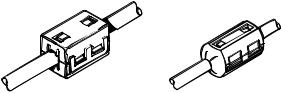
Suppression Ferrites
The following illustration shows typical cable suppression ferrites used with Raymarine equipment. Always use the ferrites supplied by Raymarine.
Figure 2-2: Typical Suppression Ferrites
Connections to Other Equipment
If your Raymarine equipment is to be connected to other equipment using a cable not supplied by Raymarine, a suppression ferrite must always be attached to the cable that is closest to the Raymarine unit.

2-4 |
DSM250 Digital Sounder Module |
2.2 Unpacking and Inspecting the Components
Unpack your system carefully, to prevent damage to the equipment. Save the carton and packing, in case you need to return a unit for service.
Check that you have all the correct system components. These depend on your system package, as follows:
Table 2-1: Parts and Accessories
Item |
Part No. |
Supplied / Option |
|
|
|
|
|
DSM250 Digital Sounder Module |
E62007 |
supplied |
|
|
|
|
|
Handbook, DSM250 |
81211 |
supplied |
|
Handbook, Transducers for Fishfinders |
81196 |
supplied |
|
Quick Reference Card, Fishfinder mode |
86066 |
supplied |
|
|
|
|
|
Mounting screws, #8 (x4) |
N/A |
supplied |
|
|
|
|
|
Power cable, 3 pin, 3 m |
R69053 |
supplied |
|
|
|
|
|
hsb2 cable assy |
R55001 |
option |
|
3 ft 3 in (1 m) |
|||
10 ft (3 m) |
R55002 |
supplied |
|
R55003 |
option |
||
20 ft (6 m) |
|||
R55004 |
option |
||
30 ft (10 m) |
|||
E55010 |
option |
||
60 ft (20m) |
|||
R58117 |
option |
||
hsb2 In Line Terminator |
|||
hsb2 Splitter Cable |
E55040 |
option |
|
|
|
|
|
Transducer and Cables (See 81196 |
— |
— |
|
Transducers for Fishfinders Handbook) |
|
|
|
|
|
|
2.3 Selecting the Equipment Location
Sounder Module Mounting Location
The DSM250 is waterproof to CFR46 is and designed to be mounted either above or below deck. The unit should be protected from physical damage and excessive vibration.
WARNING:
Mount the DSM250 in a protected area away from prolonged exposure to rain, salt spray, and direct sunlight, but well ventilated. Locate the sounder as close to the transducer as possible. Raymarine suggests not locating the DSM250 on the main console.
Chapter 2: Installation |
2-5 |
CAUTION:
Do not mount the DSM250 in the engine compartment.
When planning the installation, the following should be considered to ensure reliable and trouble free operation:
•Access: There must be sufficient space below the unit to enable cable connections to the panel connectors, avoiding tight bends in the cable.
•Interference: The selected location should be far enough away from devices that may cause interference, such as motors, generators, and radio transmitter/receivers (see the EMC guidelines earlier in this section).
•Magnetic compass: Mount the unit at least 3 ft (1m) away from a magnetic compass.
•Cable runs: The unit must be located near a DC power source. The power cable supplied is 10 ft (3 m), but a longer cable can be used if desired. Refer to Section 2.4.
The maximum length of cable between the sounder module and the transducer unit should not normally exceed 30 ft (10 m). If you need to use a longer cable, refer to Section 2.4.
•Environment: Good ventilation is required to prevent the unit from overheating.
CAUTION:
Removal of the transducer cable from the DSM250 while power is turned on can cause sparks. As with any electronic device, be sure the sounder module is mounted where it is well ventilated and free from gasoline fumes.
2.4Cable Runs
Consider the following before installing the system cables:
•You will need to attach the power, transducer, and HSB cables. Additional cables will be required if you are installing an integrated system.
•All cables should be adequately secured, protected from physical damage, and protected from exposure to heat.
Avoid running cables through bilges or doorways, or close to moving or hot objects.
•Sharp bends must be avoided.
2-6 |
DSM250 Digital Sounder Module |
•Where a cable passes through an exposed bulkhead or deckhead, a watertight feed-through should be used.
•Secure cables in place using tie-wraps or lacing twine. Coil any extra cable and tie it out of the way.
You will need to run the following cables:
•Power cable, supplied with the unit. This 10 ft (3 m) cable has a connector plug at one end for connecting to the sounder module, and 3 wires at the other end for connecting the power supply. The power cable may be extended by up to 60 ft (20 m) using a wire gauge of AWG 12 or greater. The DSM250 is intended for use on ships’ DC power systems rated from 10.7 V to 32 V.
•HSB cable, supplied with the unit. This 10 ft (3m) cable is used to connect the DSM250 to the display unit. Other lengths of HSB cables are available from Raymarine. See Table 2-1 Parts and Accessories on page 2-4.
•Transducer cable, supplied with the transducer. This 30 ft (10 m) cable has a connector plug (with an outer nut that you must attach) at one end for the display unit or extension cable. The transducer cable may be extended up to a maximum of 60 ft (20 m) using optional extension cables. For details, see document number 81196, Transducers for Fishfinders Owner’s Handbook.
WARNING:
Do not cut the transducer cable or remove the connector. Do not try to shorten or splice the cable. Cutting the transducer cable will severely reduce sonar performance.
If the cable is cut, it must be replaced—it cannot be repaired. Cutting the cable will also void the warranty.
Chapter 2: Installation |
2-7 |
1.65 in |
(41.8 mm) |
3.46 in |
(88 mm) |
|
|
Weight: 2.2 lbs (1.0 Kg) |
|
9.96 in (252.9 mm) |
Compass Safe Distance: 39 in (1 m) |
|
|
|
|
|
2.43 in (61.7 mm) |
|
|
D6168-1 |
|
9.51 in (241.6 mm) |
7.37 in (187.2 mm) |
|
10.76 in (273.3 mm) |
|
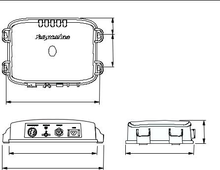
Figure 2-3: |
DSM250 Unit Dimensions |
|
2-8 |
DSM250 Digital Sounder Module |
2.5 Mounting the Sounder Module
The DSM250 can be installed either above or below deck using the supplied hardware.
CAUTION:
Do not mount the DSM250 in the engine compartment.
To allow for proper water drainage and ease of cable connection, the DMS250 should be mounted vertically, so that the cables can hang below the unit, as in Figure 2-4 .
To mount the DSM250:
1.Hold the module in the location where you want to mount it, making sure the unit is perpendicular to the floor, as in Figure 2-4 .
2.With a pencil, mark the tops (narrow ends) of the four key holes onto the mounting surface. Set aside the module.
3.Drill a 9/64" pilot hole at each of the four marked locations.
Note: For fiberglass with a gelcoat surface, you should overdrill the surface to prevent the gelcoat from chipping when driving in the screw. Before drilling the pilot hole, hand drill the marked location with an oversized bit and countersink to approximately 3/8" diameter.
4.Drive the supplied #8 screws into the pilot holes. Screw them in about half way.
5.Mount the module to the surface, slipping the screw heads through the four key holes.
6.Press the module downward so the screws align with the narrow end of the keyholes.
7.Tighten the screws. Do not overtighten.

Chapter 2: Installation |
2-9 |
D6183-1
Figure 2-4: Mounting the DSM250
2.6 System Connections
The rear of the display unit provides the following connection sockets:
•Transducer connection.
•Ground connection.
•Power, for 12 V, 24 V, or 32 V DC power connection and one RF ground (screen) connection.
•HSB, in/out connector for connecting to an hsb2 PLUS Series display (Chartplotter, Fishfinder or Pathfinder Radar)
D6161-1
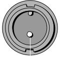
Figure 2-5: DSM250 Connector Panel
The following sections detail the connectors used when installing the DSM250.
2-10 |
DSM250 Digital Sounder Module |
DC Power Connection
The DSM250 is intended for use on ships’ DC power systems rated from 10.7 V to 32 V.
The power connection to the unit should be made at either the output of the battery isolator switch, or at a DC power distribution panel. Raymarine recommends that power is fed directly to the DSM250 via its own dedicated cable system and MUST be protected by a thermal circuit breaker or fuse on the red (positive) wire, installed close to the power connection.
A 10 ft (3 m) power cable is supplied for connecting the ship’s DC power to the unit. The power cable may be extended by up to 60 ft (20 m) using a wire gauge of AWG 12 or greater.
DC power is connected at the three-pin POWER connector on the unit’s connector panel. The connector (viewed from the outside) and pin functions are shown in the following diagram and table.
f
1 


 2
2
|
|
|
|
3 |
|
|
|
|
|
|
|
|
|
|
|
D6162-1 |
|
Figure 2-6: |
Power Connector |
|
|
|
|
|
|
|
|
|
|
Pin No. |
Function |
Color |
|||
|
|
|
|
|
|
1 |
Battery positive (12/24/32 V systems) |
Red |
|||
|
|
|
|
|
|
2 |
Battery negative |
Black |
|||
|
|
|
|
|
|
3 |
Shield (drain wire) |
No insulation |
|||
|
|
|
|
|
|
The RED wire must be connected to the feed from the positive (+) battery terminal and the BLACK wire to the feed from the negative (–) battery terminal. The shield wire (drain) should be connected to the ship’s RF ground as described in Ground Connection on page 2-11.
Install a quick blow 8 amp fuse on the red (positive) wire.
Loading...