


RL70C

Distributed by
Any reference to Raytheon or
RTN in this manual should be
interpreted as Raymarine.
The names Raytheon and RTN
are owned by the
Raytheon Company.

HSB Series
LCD Display
Owner’s
Handbook
Document number: 81163_1
Date: 1st September 1999

Preface i
HSB Series LCD Display
Owner’s Handbook
September 1999
SAFETY NOTICES
This radar equipment must be installed and operated in accordance with the
instructions contained in this manual. Failure to do so can result in personal
injury and/or navigational inaccuracies. In particular:
1. HIGH VOLTAGE. The LCD display unit and scanner unit contain high
voltages. Adjustments require specialised service procedures and tools only
available to qualified service technicians – there are no user serviceable parts or
adjustments. The operator should never remove the display unit cover or
attempt to service the equipment.
2. ELECTROMAGNETIC ENERGY. The radar scanner transmits
electromagnetic energy. It is important that the radar is turned off whenever
personnel are required to come close to the scanner to perform work on the
scanner assembly or associated equipment.
It is recommended that the radar scanner is mounted out of range of personnel
(above head height).
Avoid looking directly at the antenna as your eyes are the most sensitive part of
the body to electromagnetic energy.
When properly installed and operated, the use of this radar will conform to the
requirements of ANSI/IEEE C95.1-1992 Standard for Safety Levels with
Respect to Human Exposure to Radio Frequency Electromagnetic Fields, 3Hz
to 300 GHz and NRPB, Board Statement on Restrictions on Human Exposure
to Static and Time Varying Electromagnetic Fields and Radiation. Doc NRPB,
N0. 5 (1993).
3. NAVIGATION AID. This radar unit is only an aid to navigation. Its
accuracy can be affected by many factors, including equipment failure or
defects, environmental conditions, and improper handling or use. It is the user’s
responsibility to exercise common prudence and navigational judgements. This
radar unit should not be relied upon as a substitute for such prudence and
judgement.

ii
HSB Series LCD Display
RAYTHEON MARINE products are supported by a network of Authorized
Service Representatives. For information on Raytheon products and services,
contact either of the following:
UNITED STATES Raytheon Marine Company
676 Island Pond Road
Manchester, NH 03109-5420
Telephone: (603) 647-7530
800 539-5539
Fax: (603) 634-4756
EUROPE Raytheon Marine Limited
Anchorage Park
Portsmouth
Hampshire PO3 5TD
England
Telephone: (+44) 1705 693611
Fax: (+44) 1705 694642
Copyright © Raytheon Marine Company 1999
The technical and graphical information contained in this handbook, to the best
of our knowledge, was correct as it went to press. However, the Raytheon
policy of continuous improvement and updating may change product
specifications without prior notice. As a result, unavoidable differences
between the product and handbook may occur from time to time, for which
liability cannot be accepted by Raytheon.
Raytheon is a registered trademark of Raytheon Company.
SeaTalk is a registered trademark of Raytheon Marine Europe Limited.
HSB is a trademark of Raytheon Marine Company.
Pathfinder is a trademark of Raytheon Marine Company.
This product contains technology provided under license by Acorn Group plc.
The copyright of this intellectual property is acknowledged by Raytheon
Marine Company, as are Acorn’s trademarks and patents. Acorn’s world wide
web address is http://www.acorn.com.

Preface iii
Preface
This handbook covers the radar and chart aspects of the following HSB Series
systems from Raytheon:
SystemSystem
SystemSystem
System
DisplayDisplay
DisplayDisplay
Display
ScannerScanner
ScannerScanner
Scanner
ChartplotterChartplotter
ChartplotterChartplotter
Chartplotter
Pathfinder Radar RL70 Yes No
Chartplotter RC520 No Yes
Combined Pathfinder
Radar/Chartplotter RL70RC Yes Yes
Repeater Display RL70 No No
Repeater Display RL70RC No Yes
Repeater Display RC520 No Yes
Notes: Radar systems are supplied with an appropriate Raytheon scanner unit
and inter-connecting cable. Details for installing the scanner are described in
the Pathfinder Radar Scanner Owner’s Handbook.
The chartplotter display unit includes a cartridge holder assembly which
contains two slots for C-MAP NT chart cards.
This handbook contains very important information on the installation and
operation of your new equipment. In order to obtain the best results in operation
and performance, please read this handbook thoroughly.
Raytheons Product Support representatives or your local dealer will be
available to answer any questions you may have.
Warranty
To register your HSB Series display unit ownership, please take a few minutes
to fill out the warranty registration card found at the end of this handbook. It is
very important that you complete the owner information and return the card to
the factory in order to receive full warranty benefits.
EMC Conformance
All Raytheon equipment and accessories are designed to the best industry
standards for use in the leisure marine environment.
When powered up, all electrical equipment produces electromagnetic fields.
These can cause adjacent pieces of electrical equipment to interact with one
another, with a consequent adverse effect on operation. In order to minimise
these efffects and enable you to get the best possible performance from your

iv
HSB Series LCD Display
Raytheon equipment, guidelines are given at appropriate points throughout this
handbook to enable you to ensure minimum interaction between different items
of equipment, i.e. ensure optimum Electromagnetic Compatibility (EMC).
The design and manufacture of Raytheon equipment and accessories conform
to the appropriate EMC standards, but correct installation is required to ensure
that performance is not compromised.

Contents v
Contents
Chapter 1: Overview ............................................................................ 1
1.1 Introduction ................................................................................. 1
How to Use This Handbook .................................................... 1
Terminology .......................................................................... 3
General ....................................................................................... 3
Display Unit ........................................................................... 4
Scanner ................................................................................. 4
Display Unit Features .................................................................. 5
Operating Modes ......................................................................... 5
Window Options .................................................................... 5
1.2 The Pathfinder Radar Display ...................................................... 7
Pathfinder Radar Display Options ................................................ 7
Radar Functions ......................................................................... 10
1.3 The Chartplotter Display .............................................................11
Chartplotter Display Options ...................................................... 11
Chartplotter Functions ................................................................ 12
1.4 Operating Controls ......................................................................14
Trackpad and Cursor ..................................................................14
Moving the Cursor ................................................................15
Context-Sensitive Cursor Control .......................................... 15
Dedicated Keys .......................................................................... 16
Soft Keys ................................................................................... 16
Pop-Up Menus ........................................................................... 17
Database Lists ............................................................................18
Chapter 2:
Getting Started & Adjusting the Display .......................................... 19
2.1 Introduction ................................................................................19
Conventions Used ...................................................................... 19
Simulator ...................................................................................19
2.2 Switching the Display On and Off ...............................................20
Radar Mode .......................................................................... 20
Chart Mode ...........................................................................22
Simulator Mode .........................................................................23
Changing the Lighting and Contrast ............................................ 24

vi
HSB Series LCD Display Unit
2.3 Controlling the Display ...............................................................25
Selecting the Mode of Operation ................................................. 25
Selecting a Half-Screen Window for Display .......................... 26
Switching Control Between Radar & Chart Screens ................ 29
Returning to the Full-Screen Display ......................................29
Customising the Screen Presentation Options .............................. 31
Switching the Cursor Data Box On and Off .............................31
Switching Radar Range Rings or Chart Grid On and Off ..........31
Data Boxes ...........................................................................32
Waypoint Display - Radar mode ............................................ 32
Custom Options - Chart mode ................................................ 33
2.4 Radar Display Control Functions .................................................34
Using the Zoom Function ............................................................34
Offsetting the Centre .................................................................. 35
Hiding the Ship’s Heading Marker (SHM) ...................................36
2.5 Chart Display Control Functions ................................................ 37
Moving Around the Chart ........................................................... 37
Changing the Chart Centre ..................................................... 37
Using FIND SHIP ................................................................. 38
Changing the Chart Scale .......................................................39
2.6 Typical Chart Scenarios ...............................................................41
Place and Goto A Waypoint .............................................................. 42
Make and Follow a Route ..................................................................44
Review Your Passage Plan ................................................................ 46
Displaying the Radar and Synchronising Radar & Chart ..................... 48
Chapter 3: Standard Radar Operations ............................................. 51
3.1 Introduction ................................................................................51
3.2 Range Control .............................................................................52
Changing the Range ................................................................... 52
The Standard Range Scale .....................................................52
Determining Actual Radar Range ................................................ 53
3.3 Interpreting and Adjusting the Radar Picture ............................... 54
Identifying False Echo Returns ....................................................55
Side Lobes ............................................................................ 55
Indirect Echoes ..................................................................... 56
Multiple Echoes .................................................................... 56
Blind Sectors or Shadow Effect ..............................................56

Contents vii
Adjusting Gain, Sea Clutter and Rain Clutter ............................... 57
Gain Control and Sea Control ................................................ 58
Tuning the Receiver ..............................................................59
Rain Clutter Control, using RAIN and FTC ............................ 60
Changing the Targets Display ..................................................... 61
Interference Rejection ...........................................................62
Target Expansion .................................................................. 62
Target Wakes ........................................................................62
3.4 Measuring Range and Bearing Using VRM/EBLs ........................ 63
Measuring Range and Bearing to Target from Vessel ...................64
Placing a VRM/EBL ............................................................. 64
Moving an Existing VRM/EBL ............................................. 65
Deleting an Existing VRM/EBL ............................................ 66
Measuring Range and Bearing Between Targets (FLOAT) ...........66
Floating a VRM/EBL ............................................................ 66
Moving and Unfloating a Floating EBL .................................. 67
Controlling VRM/EBL Data Boxes .............................................68
3.5 Setting Guard Zones and Alarms ................................................. 69
Placing a Guard Zone ................................................................. 70
Moving, Reshaping or Deleting a Guard Zone ..............................71
Controlling Guard Zone Alarms .................................................. 72
Chapter 4: Integrated Radar Operations .......................................... 73
4.1 Introduction ................................................................................73
4.2 Changing the Heading Mode ....................................................... 74
Heading Modes .......................................................................... 74
Selecting the Heading Mode ....................................................... 75
Effect on VRM/EBLs ................................................................. 75
4.3 Using Marks ............................................................................... 76
Placing a Mark ........................................................................... 76
Moving or Deleting a Mark ......................................................... 77
4.4 Man Overboard (MOB) ...............................................................77
4.5 Cursor Echo ............................................................................... 78

viii
HSB Series LCD Display Unit
Chapter 5: Standard Chart Operations ............................................. 79
5.1 Introduction ................................................................................79
Safety ................................................................................... 79
5.2 Using Chart Cards ....................................................................... 80
Inserting a Chart Card ................................................................. 80
Removing a Chart Card ..............................................................81
Displaying the Chart Data ...........................................................81
Displaying Object Information .................................................... 82
Chart Source Data ................................................................. 82
Port Area .............................................................................. 83
Tide Data .............................................................................. 84
Nearest ................................................................................. 85
5.3 Working with Waypoints ............................................................86
Introduction ...............................................................................86
Placing a Waypoint .................................................................... 87
Selecting a Waypoint ..................................................................88
Waypoint Data Display ...............................................................88
Editing the Waypoint Details ...................................................... 89
Erasing a Waypoint .................................................................... 90
Moving a Waypoint ....................................................................91
5.4 Working with Routes .................................................................. 92
Creating a New Route ................................................................. 93
Saving the Current Route ............................................................ 94
Clearing the Current Route ..........................................................95
Retrieve a Route From the Database ............................................ 96
Displaying Route Information ..................................................... 96
Route Leg and Waypoint Information ....................................97
Using Route Information to Review Your Passage Plan ...........97
Using the Route List to Erase and Name a Route .......................... 98
Editing a Route ...........................................................................99
Inserting a Waypoint into a Route ...........................................99
Adding Waypoints at the End of the Route ............................ 100
Removing a Waypoint from the Route .................................. 100
Reversing the Route ............................................................ 100
5.4 Following Routes and Going to Points ........................................ 101
Follow a Route ......................................................................... 102
Target Point Arrival .................................................................. 103
Other Follow Route Options ..................................................... 103

Contents ix
Joining a Route ................................................................... 103
Advancing to a Waypoint .................................................... 104
Restart Cross Track Error (XTE) ..........................................104
Going To an Individual Target Point .......................................... 104
Stop Follow or Stop Goto ..........................................................105
5.6 Transferring Waypoints and Routes ........................................... 106
Displayed SeaTalk Waypoints ............................................. 106
Managing Database Lists ..................................................... 106
5.7 Using Tracks .............................................................................108
Setting Up a Track .................................................................... 108
Clearing the Current Track ........................................................ 109
Managing Tracks ..................................................................... 109
Saving and Naming a Track ................................................. 109
Naming, Erasing and Showing a Track ................................. 110
Chapter 6: Further Chart Operations ............................................... 111
6.1 Introduction .............................................................................. 111
6.2 Measuring Distances Using the VRM/EBL Key ........................ 112
6.3 Alarms and Timers ................................................................... 114
Alarm Reporting ...................................................................... 114
External Alarms .................................................................. 114
Setting Alarms and Timers ........................................................ 114
6.4 Man Overboard (MOB) ............................................................ 116
6.5 Cursor Echo .............................................................................. 117
6.6 GPS Setup ................................................................................ 118
6.7 Data Log Mode ......................................................................... 119
Chapter 7: Setting Up the System Defaults .....................................121
7.1 Introduction .............................................................................. 121
7.2 Changing the Set Up Parameters ................................................ 122
7.3 System Set Up Parameters ........................................................ 124
Data Boxes .............................................................................. 126
Bearing Mode .......................................................................... 126
Cursor Reference ..................................................................... 126
Cursor Readout ........................................................................ 126
Day/Night ................................................................................ 127
Help ........................................................................................ 127
Soft Keys ................................................................................. 127
Key Beep ................................................................................. 127

x
HSB Series LCD Display Unit
MOB Data ............................................................................... 127
Menu Timeout Period ............................................................... 127
Units ........................................................................................ 128
Variation Source ...................................................................... 128
Auto Mode ......................................................................... 128
Manual Mode ..................................................................... 128
Cursor Echo ............................................................................. 129
Date and Time Settings ............................................................. 129
Language ................................................................................. 130
Simulator ................................................................................. 130
7.4 Radar Set Up Parameters .......................................................... 131
EBL Display ............................................................................ 131
Timed Transmission Option ......................................................132
Marks Options ......................................................................... 132
Custom Scale ........................................................................... 132
Bearing Alignment ................................................................... 133
7.5 Advanced Settings .................................................................... 134
Display Timing ........................................................................ 134
STC Preset ............................................................................... 135
Tune Preset .............................................................................. 135
7.6 Chart Set Up Parameters ............................................................ 136
Customise Chart ....................................................................... 136
Plotter Mode ............................................................................ 137
Chart Orientation ...................................................................... 137
Object Information ................................................................... 138
Waypoint Options .................................................................... 138
Vectors .................................................................................... 138
Radar/Chart Synch ................................................................... 138
Datum Selection ....................................................................... 138
Chapter 8: Installation ...................................................................... 141
8.1 Introduction .............................................................................. 141
Planning the Installation ............................................................142
EMC Installation Guidelines ..................................................... 142
8.2 Unpacking and Inspecting the Components ................................144
8.3 Selecting the Display Unit Site ................................................... 145

Contents xi
8.4 Cable Runs ............................................................................... 147
Power Cable .............................................................................147
Inter-Unit Cable ....................................................................... 148
8.5 Mounting the Display Unit ........................................................ 149
Trunnion (Yoke) Mounting .......................................................149
Console Mounting .................................................................... 150
8.6 Display Unit Connections .......................................................... 151
Grounding the System ......................................................... 151
DC Power Connection ......................................................... 151
Power for External Equipment ............................................. 151
Display Unit Connection .......................................................... 152
Scanner Connection (master displays) .................................. 153
Power and NMEA Input Connection .................................... 154
8.7 Radar System Tests and Post Installation Alignment ................... 155
System Check .......................................................................... 155
Switch On and Initial Setup ....................................................... 155
Radar System Checks and Adjustments ..................................... 156
Transmission Check ............................................................ 156
Bearing Alignment .............................................................. 157
Display Timing Adjustment .................................................158
EMC Conformance .................................................................. 159
8.8 Integrated Systems .................................................................... 160
Power for External Equipment ............................................. 160
HSB™ High Speed Bus ............................................................161
HSB Connection ................................................................. 161
SeaTalk® and NMEA In .......................................................... 162
........................................................................................... 163
SeaTalk .............................................................................. 164
SeaTalk Connection ............................................................ 164
NMEA 0183 ....................................................................... 166
NMEA Input Connection .....................................................166
Using the SeaTalk Auxiliary Junction Box .................................167
Data Output ............................................................................. 168
Data Conversion .......................................................................168
8.9 Integrated System Checks ........................................................ 169
Chart Display - RL70RC, RC520 .............................................. 169
Received Data .......................................................................... 169
Transmitted Data ......................................................................169

xii
HSB Series LCD Display Unit
Chapter 9: Maintenance and Problem Solving ............................... 171
9.1 Maintenance ............................................................................ 171
Warnings ................................................................................. 171
Routine Checks ........................................................................ 171
EMC Servicing and Safety Guidelines ....................................... 171
9.2 Resetting the System ................................................................. 172
9.3 Problem Solving ....................................................................... 173
Common Problems and Their Solutions .....................................173
How to Contact Raytheon (US) ................................................. 173
For Marine Product and Services Information ....................... 173
For Accessories and Parts .................................................... 173
For Technical Support: ........................................................ 174
For Product Repair and Service ............................................ 174
How to Contact Raytheon (Europe) ........................................... 175
Technical Support ............................................................... 175
Accessories and Parts .......................................................... 175
Worldwide Support .................................................................. 175
Appendix A: Specification ................................................................177
HSB Series 7" LCD Displays .................................................... 177
General ...............................................................................177
Radar Features .................................................................... 178
Chartplotter Features ........................................................... 179
Interfacing .......................................................................... 180
Appendix B: Using the Auxiliary Junction Box to Connect a SeaTalk
GPS and Differential Beacon Receiver .............................................181
Raystar 112, 105, Apelco 182 and 182XT .................................. 182
Autohelm GPS, Z260 and Z273 ................................................ 183
Raystar 112LP (SeaTalk version) .............................................. 184
Raystar 114 Combined GPS and Differential Beacon Receiver ... 185
Appendix C: C-MAP Chart Card Features .........................................187
Appendix D: SeaTalk and NMEA Data Received and Transmitted . 191
Abbreviations ................................................................................... 193
Index ..................................................................................................195

Chapter 1: Overview 1
Chapter 1: Overview
1.1 Introduction
This handbook describes the following HSB Series systems:
RL70 Pathfinder Radar, 7" LCD Display
RL70RC Combined Pathfinder Radar/Chartplotter, 7" LCD Display
RC520 Chartplotter, 7" LCD Display
If you have an HSB Series LCD display, it is possible to connect another HSB
series LCD or CRT display to provide an integrated system. Connecting an
HSB Series Pathfinder Radar display to a chartplotter provides similar
functionality to the Combined Pathfinder Radar/Chartplotter display; the radar
data can be repeated on the chart display and chart data repeated on the radar
display.
If you are using the 7" LCD display unit as a repeater display refer to this
handbook for details on the operating controls.
This handbook describes the display unit controls and details both radar and
chart operations. Controls that are specific to either radar or chartplotter are
described in radar or chart sections/chapters.
Note: Many illustrations in this handbook show example screens. The screen
you see on your display depends on your system configuration and set up
options, so it may differ from the illustration.
How to Use This Handbook
For an overview of the display unit, the radar and the chartplotter systems, read
Chapters 1 and 2 of this handbook. Having read these chapters you should be
able to start using your system.
For detailed information on radar operations refer to Chapters 3 and 4.
For chartplotter operating details, refer to Chapters 5 and 6.
To change the system set up defaults, read Chapter 7.
If you are installing the display system yourself, you should read Chapter 8
before you start the installation. This chapter also provides information that will
be useful if you are connecting your HSB Series system to other equipment.
Details for installing a radar scanner are provided in the Scanner User’s
Handbook supplied with your scanner.
Chapter 1
Overview

2
HSB Series LCD Display
The handbook is organised as follows:
Chapter 1 provides an overview of the features and functions of the HSB
Series LCD Display. This chapter also provides an overview of the controls.
You should read this chapter to familiarise yourself with the system.
Chapter 2 explains how to start using the display and describes how to use
some of the basic radar and chart functions. Chapter 2 also provides operating
guidelines for typical chartplotter scenarios; these guidelines introduce you to
many of the chartplotter functions.
Chapters 3 provides detailed operating information for the main radar
functions - adjusting the radar picture; measuring distances and bearings;
setting guard zones and alarms.
Chapter 4 provides detailed operating information for integrated radar system
functions, including using marks, man overboard and cursor echo.
Chapter 5 provides detailed operating information for the standard chartplotter
functions - using chart cards, plotting waypoints and routes, following routes
and showing tracks.
Chapter 6 provides detailed operating information for further chart functions,
including measuring distances, man overboard and cursor echo. It includes
instructions for setting up a differential GPS.
Chapter 7 provides instructions for setting up your system to suit your
preferences. You should read this chapter to determine how to set up theradar
and chartplotter system defaults.
Chapter 8 provides planning considerations and detailed instructions for
installing the display unit. It should be referred to when you are ready to install
the system. Details to connect the display to other equipment are also provided.
To install a complete radar system, you will also need to read to the Owner’s
Handbook supplied with the scanner.
Chapter 9 provides information on user maintenance, and what to do if you
experience problems.
The Appendices provide additional information that you may find useful:
Appendix A lists the technical specifications for the radar and for the
chartplotter.
Appendix B provides details on connecting the display unit to specific GPS
systems.
Appendix C defines the chart features shown on the chart display.
Appendix D defines the SeaTalk and NMEA data that is transferred on
integrated systems.
Introduction

Chapter 1: Overview 3
A List of Abbreviations, Index and warranty information are included at the
end of the handbook.
A summary of the radar and chartplotter controls are provided on the Quick
Reference Cards supplied with your system.
Terminology
The following terminology is used to describe radar and chartplotter systems:
Master A unit capable of sourcing specific data
(such as radar or chart data).
Repeater A unit capable of displaying data, such as radar,
from the HSB.
Radar Display Unit providing Radar Master and Chart Repeater
functionality.
Chart Display Unit providing Chart Master and Radar Repeater
functionality.
Combined Display Unit providing both Radar and Chart Master
functionality.
Integrated System Additional instruments are connected via the
HSB, Seatalk or NMEA interfaces.
HSB™ High Speed Bus - links compatible display units.
For full display and control between HSB series
display units, the units must be connected via
HSB and SeaTalk.
General
The HSB Series Pathfinder Radar or Pathfinder Radar/Chartplotter, illustrated
below, comprises the 7" LCD display unit, scanner unit and associated cables.
The RC520 Chartplotter cannot be connected to the scanner unit.
General

4
HSB Series LCD Display
Display Unit
The HSB Series LCD display unit is waterproof to CFR46 and can be installed
either above or below deck.
The unit includes:
• 7" LCD display
• Trackpad
• Eleven dedicated (labelled) control keys
• Four soft keys (unlabelled) whose functionality changes
• The chartplotter (RC520) and combined Pathfinder Radar/Chartplotter
(RL70RC) include two slots for the C-MAP NT
®
electronic chart cards
The display and keys can be illuminated for night-time use.
The HSB (High Speed Bus) connection enables transfer of data between two
compatible units. For example, the radar data is transferred from the radar (the
master display) via the HSB connection and can be displayed and controlled on
any other HSB Series LCD or CRT display (repeater display). In particular, you
can connect your HSB Series Pathfinder Radar to a remote HSB Series
Chartplotter to provide similar functionality to the combined Pathfinder Radar/
Chartplotter.
Full functionality of the HSB Series Pathfinder Radar is acheived when it is part
of an integrated system, with other equipment (in addition to another HSB unit)
connected via Seatalk or NMEA 0183. Data from this equipment including
position and waypoints is displayed on the radar and is used in calculations.
Details on connecting other equipment are given in Chapter 8.
Scanner
The HSB Series Pathfinder Radar is supplied with either a scanner unit which
illuminates targets with microwave energy and then collects the returns from
those targets. The scanner includes a sensitive low-noise front end receiver, and
a variety of clutter attenuation controls to maintain target resolution.
Installation of the scanner is described separately in the Scanner Owner’s
Handbook. The scanner is adjusted and operated from the display unit, so these
details are provided in this HSB Series LCD Display Handbook.
The scanner can be switched between transmit and standby modes. It also has a
power-saving timed transmit mode which pauses between bursts of
transmissions.
General

Chapter 1: Overview 5
Display Unit Features
• Uses position information from GPS, dGPS or Loran-C technology
• Displays and transfers SeaTalk, NMEA and HSB data
• Provides full control of data from other HSB instruments
• Three full-screen operating modes: Radar, Chart, Data Log (if appropriate
data is available)
• View radar and chart simultaneously
• Half-screen windows to display additional data: Course Deviation Indicator
(CDI), Bearing and Distance Indicator (BDI), navigation data
• Cursor echo across SeaTalk, and between chart and radar windows
• Choice of orientation: Head Up, Course Up and North Up
• Chartplotter - Displays chart information from the C-MAP NT
®
chart cards
(C-Cards)
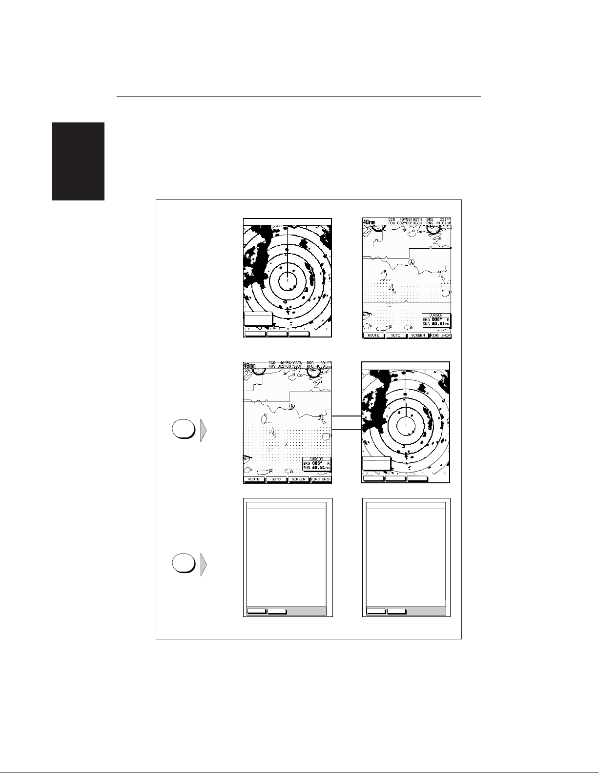
Operating Modes
If you have a combined Pathfinder Radar/Chartplotter Unit, or have both an
HSB Series Radar and Chartplotter connected, three full-screen modes are
available – chart, radar and data log – as shown in the following illustration; you
select the operating mode using the DISPLAY key as described in Chapter 2.
In addition, in chart or radar mode you can set Windows On to display
supplementary data as described below. Alternatively, on a combined radar/
chartplotter or repeat display, you can split the display into two half-screen
windows for radar and chart display.
The following information, if available on your system, can be shown:
Full-screen Mode Window Options
Radar Mode CDI, BDI, Chart or Nav Data
Chart Mode CDI, BDI, Radar or Nav Data
Data Log Mode Windows not available
Window Options
You can choose one of the following for display in the lower window:
• CDI: This gives the Course Deviation Indicator graphical display, with data
relating to the target waypoint.
• BDI: This gives the Bearing and Distance Indicator graphical display, with
data relating to the target waypoint.
• Chart display (when in Radar mode)
Radar display (when in Chart mode): If data is available, either as a
function of the combined display unit or via the HSB link, it can be
displayed.
Operating Modes
6
HSB Series LCD Display
• Nav Data: This shows nine data boxes, providing navigational data in the
units specified in your set up. Note that up to 6 of these data boxes are also
available as a user-selectable group (see Section 7.3 System Set Up
Parameters).
Details on selecting windows are given in Chapter 2.
HEAD UP
IR
3nm
RR
CURSOR
HDG MODE TARGETS SCREEN
BRG
RNG nm
000°
0.220
1/2
Radar Display Chartplotter Display
TIME POSITION CMG DMG
CLEAR LOG
STOP LOG
15:30
16:00
16:30
17:00
17:30
18:00
18:30
19:00
19:30
346°
H
180°
H
012°
H
206°
H
043°
H
245°
H
093°
H
302°
H
145°
H
50°21^890N
001°20^610W
50°18^010N
001°20^070W
50°21^850N
001°19^290W
50°18^500N
001°21^300W
50°20^990N
001°18^280W
50°19^660N
001°21^960W
50°19^730N
001°18^030W
50°20^930N
001°21^750W
50°18^550N
001°18^650W
6.86
KM
7.23
KM
7.23
KM
6.67
KM
5.74
KM
5.00
KM
4.63
KM
5.00
KM
5.74
KM
HSB
SeaTalk
D4285-1
Operating Mode for
Stand Alone Units
Additional Modes for
Linked Units
(or combined
Radar/Chartplotter)
DISPLAY
DISPLAY
TIME POSITION CMG DMG
CLEAR LOG
STOP LOG
15:30
16:00
16:30
17:00
17:30
18:00
18:30
19:00
19:30
346°
H
180°
H
012°
H
206°
H
043°
H
245°
H
093°
H
302°
H
145°
H
50°21^890N
001°20^610W
50°18^010N
001°20^070W
50°21^850N
001°19^290W
50°18^500N
001°21^300W
50°20^990N
001°18^280W
50°19^660N
001°21^960W
50°19^730N
001°18^030W
50°20^930N
001°21^750W
50°18^550N
001°18^650W
6.86
KM
7.23
KM
7.23
KM
6.67
KM
5.74
KM
5.00
KM
4.63
KM
5.00
KM
5.74
KM
HEAD UP
IR
3nm
RR
CURSOR
HDG MODE TARGETS SCREEN
BRG
RNG nm
000°
0.220
1/2
Operating Modes

Chapter 1: Overview 7
1.2 The Pathfinder Radar Display
When a scanner is connected and the radar is in Transmit mode, the radar
picture provides a map-like representation of the area in which the radar is
operating. Typically, your ship’s position is at the centre of the display, and its
dead ahead bearing is indicated by a vertical heading line, known as the Ship’s
Heading Marker (SHM).
The radar picture can be viewed with a variety of fixed or customised range
scales. A status bar at the top of the radar image displays range, current heading
and mode indicators for the various options you can set.
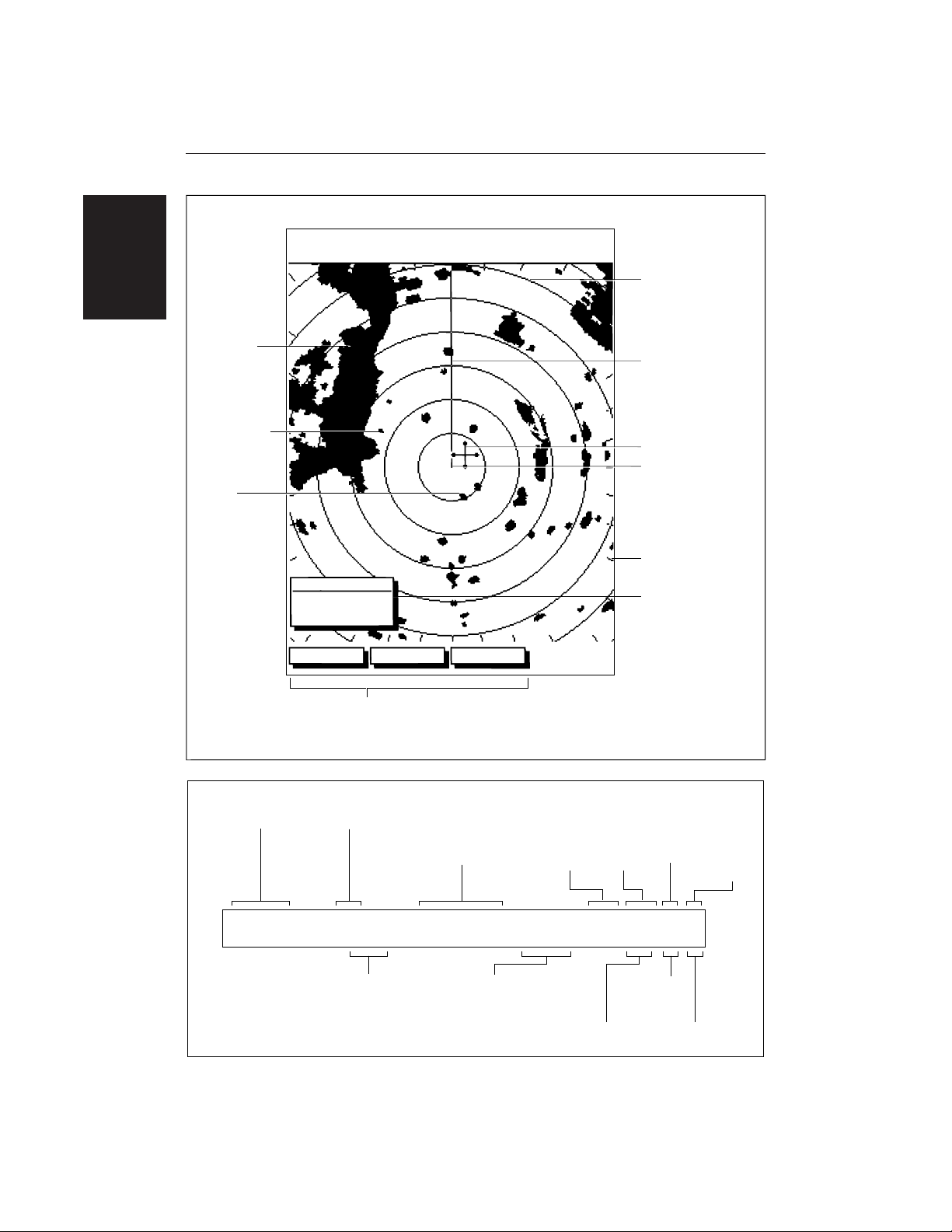
An example radar picture is shown on the next page, with example radar returns
(echoes) and default Pathfinder Radar information. The Status Bar indicator is
also illustrated.
The radar display can show additional information, depending on your
currently selected options, set up selections and the data available from other
equipment. The example displays on the following pages show some of these
features.
Functions are available to control the display as follows:
• Zoom the Display
• Offset your vessel from the centre of the radar picture
Operation of these functions is described in Chapter 2.
Pathfinder Radar Display Options
Set up options allow you to customise the radar image by choosing what is
displayed, how it is displayed (including language and units), heading mode
and how the radar operates with other HSB units. You can also view the cursor
position and a variety of data from other equipment, e.g. speed, heading, depth,
wind and tide information in a set of user-selectable data boxes. The cursor box
and user-selected data boxes can be moved around the screen and they can be
turned on or off.
Display options are provided in System Set Up and Radar Set Up as described
in Chapter 7. In addition, Screen Presentation Options, described in Chapter 2
are provided to switch:
• Cursor Box and Databoxes On/Off
• Range Rings On/Off
• Waypoint Display On/Off
Note: When you turn the display off and on again, these settings are retained in
memory.
The Pathfinder
Radar Display
8
HSB Series LCD Display
CURSOR
HDG MODE TARGETS SCREEN
BRG
RNG nm
045°
0.28
R
Landmass
Surface
vessel
Default soft key labels
These can be turned off; press any soft key to re-display them.
Different labels are displayed when you press a key.
Channel buoy
Range rings
The number and
spacing depend on
the current range, or
you can turn them off
Status Bar
Ship’s Heading
Marker (SHM)
You can hide this
temporarily
Ship’s position
You can move this
off-centre if required
Cursor position,
controlled by the
trackpad
Targets:
D3600-4
Bearing scale,
each tick indicating
2 of azimuth
Cursor position box
Shows the current
cursor position as
either Range/Bearing
or Lat/Long. You can
move this box to your
preferred position
on the screen, or
turn it off.
Default Display
126°T
AUTO
T
IR
3nm
RR
1/2
H-UP
D3993-1
Status Bar
Selected range,
in nautical miles
Range ring interval
Not displayed if
range rings are off
Range rings
(on/off)
Current heading
if heading data available,
or Course Over Ground.
Can be displayed in
degrees Magnetic or True
Heading mode
Normally Head Up (H-UP),
but you can select
Course Up (C-UP) or
North Up (N-UP) if
you have heading data
Mode Indicators
displayed when function set on:
Target
Expansion
Wakes
Interference
Rejection
Auto mode
Gain, Sea
and/or Tune
FTC
(Remote rain)
Rain
Clutter
Guard Zone
Alarms
3nm
126°T
AUTO
WKS
FTCEXRCGZIR
RR
1/2
H-UP
GST
Radar Display
Options
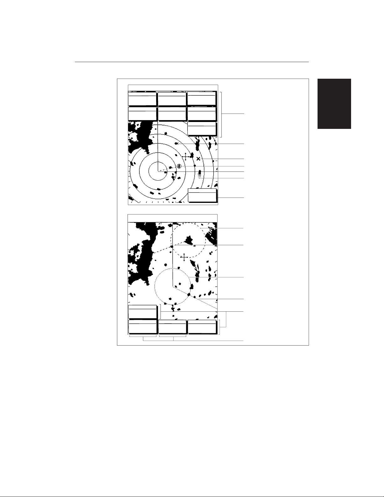
Chapter 1: Overview 9
T
AUTO
IR
015°
096
3nm
RR
OFF
VRM
VRM/EBL 2
TBRG
RNG nm
146°
1.70
CURSOR CURSOR
VRM/EBL 1
BRG
RNG nm
T
TBRG
RNG nm
50°47^72N
001°10^58N
H-UP
126°T
243°
0.98
GST
AUTO
IR
RCFTC
FTC EX
126°T
13:48:06
5.7kts
14.4m
6.3kts
3nm
RR
BRG
RNG
R
nm
CURSOR
COG
SOG
TIME
SPEED
DEPTH
WPT
1/2
50°49^13N
203°
T
1.20nm
01h:30m
001°12^09W
H-UP
POSITION
063°
1.65
120@T
Waypoint data box, showing
range, bearing and time to go
Mark, symbol selected using
setup options
Floated VRM2
(long-dashed line)
EBL1 (short-dashed line)
Long target wake (short,
medium or long wakes can
be selected)
D3601-1
Data boxes, showing data
(if available) in the selected
units
VRM/EBL data boxes
Mark, default symbol
Active waypoint - from Chartplotter
Two cursor readout boxes
Floated EBL2
(long-dashed line)
Offset centre
VRM1 (short-dashed line)
Radar Display
Options

10
HSB Series LCD Display
Radar Functions
The HSB Series Pathfinder Radar includes the following functions:
• Choice of range scales from
1
/8 nm to 72nm (dependent on scanner type).
• Automatic and manual control of tuning, gain and sea clutter.
• Two Variable Range Markers (VRMs) and Electronic Bearing Lines
(EBLs), allowing target range and bearing measurements.
VRM/EBLs can be floated.
• Target wakes and target expansion mode.
• Two guard zones with alarms.
• Add marks to record important or dangerous locations.
• Man Overboard (MOB) to navigate back to a person or object.
Operation of these radar functions is described in Chapters 3 and 4.
Radar Functions

Chapter 1: Overview 11
1.3 The Chartplotter Display
The HSB Series LCD Display can include a Chartplotter. The chartplotter
includes a small-scale world map and detailed navigation information is
displayed when a cartographic chart card is installed. A plotter mode is
provided to enable route plotting and tracking at large scales even when a chart
card is not installed
Once the position fix has been established, your vessel’s position, if on screen,
is shown as a boat shape, pointing in the direction of the current heading (or
COG if heading data is not available). If no heading or COG data is available,
the vessel is shown as a circle.
The chartplotter screen includes a status bar that displays chart scale, with either
cursor position, range and bearing or, when the cursor is homed to the vessel (by
pressing FIND SHIP), vessel position, Speed Over Ground (SOG) and Course
Over Ground (COG).
Any waypoints you have placed are displayed (unless you turned them off in
Chart Set Up as described in Chapter 7) and the current route is shown.
Information can be viewed on-screen by positioning the cursor over a waypoint,
current route or chart object. The chartplotter screen can also show additional
information, depending on your currently selected options, set up selections and
data available from other equipment.
An example chart display, in its default configuration, with a chart card
installed, is shown in the following illustration.
Several functions are available to control the display as follows:
• Zoom in/out and Pan the Display
• Offset the Chart or Centre the Chart around the Vessel
• Synchronise the Chart and Radar (if radar data is available)
Operation of these functions is described in Chapter 2.
Chartplotter Display Options
Set up options allow you to customise the chart by choosing what is displayed
(including cartographic features), how it is displayed (including language and
units), heading mode and how the chartplotter operates with other HSB units.
You can also view the cursor position and a variety of data from other
equipment, e.g. speed, heading, depth, wind and tide information in a set of
user-selectable data boxes. The cursor box and user-selected data boxes can be
moved around the screen and they can be turned on or off.
The Chartplotter
Display

12
HSB Series LCD Display
Display options are provided in System Set Up and Chart Set Up as described in
Chapter 7. In addition Screen Presentation Options, described in Chapter 2 are
provided to switch:
• Cursor Box and Databoxes On/Off
• Chart Grid On/Off
• Custom Chart Details On/Off
Note: When you turn the display off and on again, these settings are retained in
memory.
The chartplotter set up options include a sub-menu to customise the
cartographic features. This menu allows you to switch features On, Off, or
control them using the CUSTOM soft key. The factory default settings for the
Custom chart options are as follows:
ON: Chart text, chart boundaries, depth contours, navigation marks and
land features.
OFF: Caution and routing data.
CUSTOM: Spot sounding, light sectors, marine features.
Note: The factory defaut for the
CUSTOM
settings is
ON.
Icons are displayed in detail, depth shading limit is 10 m and depth contour
display is 0-100 m.
A complete list of chart features is given in Appendix C.
Chartplotter Functions
The HSB Series Chartplotter includes the following functions:
• Display C-MAP NT C_Card chart information including Ports and Tides (if
available)
• View chart information (if available) for the Nearest Port
• Place, Move, Erase and Edit a Waypoint
• Goto Waypoint or Cursor
• Create, Save, Name, Edit and Follow a Route
• Review Route and Waypoint Lists
• Display vessel’s track; Save and Name the Track for re-call to screen
• Measure Chart Distances and Bearings on-screen
• Set Up Alarms and Timers
• Man OverBoard (MOB) to navigate back to a missing person or object
• Differential GPS set up page
Operation of these functions is described in Chapters 5 and 6.
Chartplotter
Display Options

Chapter 1: Overview 13
Status Bar
Vessel Position
Cursor -
selecting chart object
Cursor position box
Shows the current
cursor position as
either Range/Bearing
or Lat/Long. You can
move this box to your
preferred position on
the screen or turn it off.
Waypoint
Object data box -
for object selected
by cursor
Default soft key labels
These can be turned off: press any soft key to redisplay them.
Different labels are displayed when you press a key.
Depth Area
Chart Range
Chart Boundary
D4275-2
Chartplotter
Functions
14
HSB Series LCD Display
1.4 Operating Controls
You operate the radar and chart systems using a variety of on-screen controls as
well as the keys on the display units. These controls include:
• A trackpad providing up, down, left, right and diagonal control of an on
screen cursor.
• Eleven dedicated (labelled) control keys.
• Four soft keys with labels displayed on the screen.
• Pop-up menus, displayed on-screen, from which you select options.
• Database lists, displayed on-screen, which enable you to edit items.
Note: The cursor is the cross-hair symbol (+) visible on the display. You move
the cursor using the trackpad and use it to select a position or item on the chart.
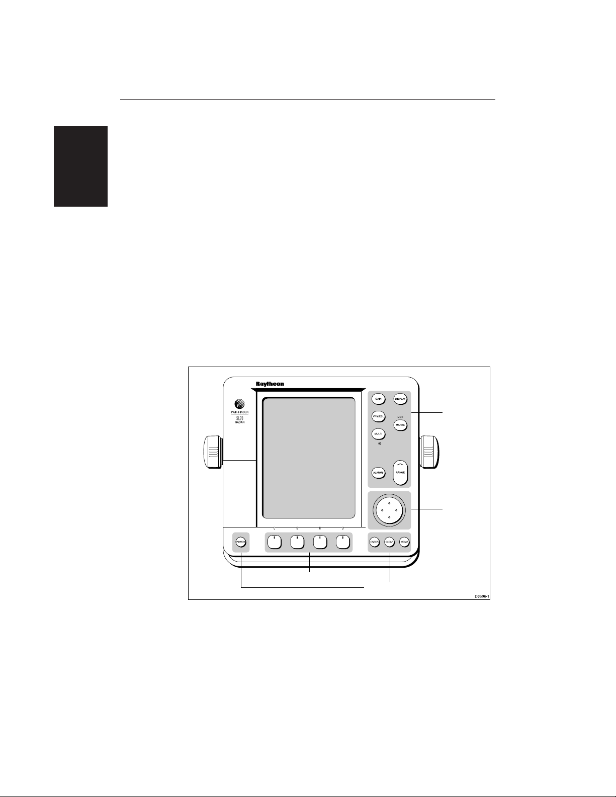
The control keys are shown on the illustration below. They are back-lit for
night-time use. When you use a control, a help message is displayed at the top of
the screen (unless you switch help off as described in Chapter 7). The following
paragraphs describe the controls and on-screen facilities.
Dedicated
keys
Trackpad
Soft keys
Dedicated keys
Trackpad and Cursor
The trackpad has several functions:
• To move the cursor around the screen
• To select an item from a pop-up menu
• To adjust a variable soft key control
Operating Controls

Chapter 1: Overview 15
The cursor is used to:
• Select a position on the screen.
• Select an item, e.g. guard zone on the radar, chart object on the chartplotter.
• Select an area of the radar image to zoom into or pan the chart display.
Moving the Cursor
You can press on any of the four sections of the trackpad to move the cursor in
that direction (up, down, left or right), or press two sections at the same time to
move diagonally. The cursor moves faster as you continue to press the trackpad.
The current cursor position is shown in the cursor data box (if selected).
Note: During many operations you cannot move the cursor around the screen;
if you cannot move the cursor using the trackpad, check the default soft keys are
displayed (unless they have been switched OFF in system set up). If not, press
ENTER until they are displayed.
The cursor is normally displayed as a crosshair. However, if you have not
moved the cursor for more than five seconds, when you next move it the cursor
is outlined by a circle so it is easier to locate on the screen.
Context-Sensitive Cursor Control
The cursor is context-sensitive. When the cursor is positioned over special
features on the display a text label appears to identify the feature as follows:
Text Label Feature Radar/Chart
BOX Data box (any type) Both
MRK Radar Mark Both
MOB Man Over Board marker Both
WPT Chart Waypoint Both
CTR Centre of radar Radar
FLT Floating EBL/VRM Radar
GRD Guard zone Radar
SHM Ships Heading Marker Radar
VRM/EBL VRM and EBL, 1 or 2 Radar
ZMB Zoom box Radar
A-B Ruler line Chart
COG Course Over Ground vector Chart
Operating Controls

16
HSB Series LCD Display
HDG Heading vector Chart
POS Vessel’s position Chart
RTE Route leg Chart
TIDE Tide vector Chart
Chart Icons Various Chart
Some items on the radar screen, such as the cursor and man overboard marker
have information associated with them. The information is displayed in a data
box. The context-sensitive cursor allows you to move databoxes.
Dedicated Keys
The dedicated keys: DISPLAY, MARKS, GAIN, VRM/EBL, MULTI, ALARMS,
RANGE, ENTER, CLEAR, MENU and POWER have fixed functions; the
functions are similar on all HSB Series displays. For example, ALARMS is used
to set up the system alarms on both a chartplotter and a radar.
Some keys can be used in two ways:
• Press: Press the key momentarily and then release it. This method is used for
most key operations.
• Press and hold: Press the key and hold it down for the length of time stated
(for example, 3 seconds), and then release it.
When you press a dedicated key, one of the following happens:
a) The associated operation is actioned, e.g. change chart scale (RANGE).
b) A pop-up menu is displayed, providing further options.
c) A set of soft keys is displayed, providing further functions.
As you press a key, a single audio beep confirms the key action. If the key-press
is not valid for the current screen or mode, three rapid beeps sound to indicate
that no response is available. If required, you can turn the key beeps off as part
of your set up procedure (see Chapter 7).
Soft Keys
The four keys below the screen are called soft keys because their functions
change according to the operation. The soft keys are grouped into related sets
and subsets providing access to the various functions. The soft key labels are
displayed on the screen just above the keys. The default soft keys are displayed
until you press a key, or select an item on the screen; the soft keys associated
with the action are then displayed.
Operating Controls
 Loading...