


A60 and RS12
Display & GPS
Installation Manual
Document number: 87081-1
Date: December 2006
Trademarks and registered trademarks
Raymarine is a registered trademark of Raymarine plc. Navionics is a registered trademark of Navionics Company, Italy.
All other product names are trademarks or registered trademarks of their respective owners.
Contents of this handbook © Raymarine 2006

|
|
3 |
Contents |
|
|
|
Trademarks and registered trademarks ............................................ |
2 |
Important Information ......................................................................................... |
5 |
|
|
Suppression Ferrites.......................................................................... |
7 |
|
Connections to Other Equipment ..................................................... |
8 |
Chapter 1: Introduction ....................................................................................... |
9 |
|
1.1 |
Selecting the Display Unit Location ........................................................ |
9 |
1.2 |
What Comes in the Box ........................................................................ |
10 |
1.3 |
Optional Equipment ............................................................................. |
11 |
1.4 |
Unit Size ............................................................................................... |
12 |
Chapter 2: Installing the Display Unit .............................................................. |
13 |
|
2.1 |
Mounting ............................................................................................. |
13 |
|
Mounting Bracket Method.................................................................... |
13 |
|
Flush Mounting..................................................................................... |
14 |
2.2 |
Cable Runs............................................................................................ |
15 |
|
Making the Cable Connections............................................................. |
16 |
|
Power Input Cable (R08003)................................................................. |
16 |
|
Power Supply.................................................................................. |
17 |
|
NMEA Cable (R08004).......................................................................... |
18 |
|
GPS Cable ............................................................................................ |
18 |
Chapter 3: Installing the GPS Antenna............................................................. |
19 |
|
3.1 |
Selecting the Mounting Location ......................................................... |
19 |
|
Receiver Location ................................................................................. |
19 |
|
Cabling Route ...................................................................................... |
20 |
3.2 |
Mounting the Receiver ......................................................................... |
20 |
|
Pole Mounting ...................................................................................... |
20 |
|
Surface Mounting ................................................................................ |
21 |
|
Making the Cable Connections ............................................................ |
22 |
Chapter 4: Maintenance .................................................................................... |
23 |
|
4.1 |
Introduction ......................................................................................... |
23 |
|
Servicing and Safety.............................................................................. |
23 |
|
Routine Checks .................................................................................... |
23 |
|
Cleaning the Display Window .............................................................. |
24 |
|
Recommended Cleaning Procedure ............................................... |
24 |
4.2 |
Resetting the System ............................................................................ |
24 |
|
Power-on Reset .............................................................................. |
24 |
|
Settings Reset ................................................................................ |
25 |
|
Settings and Data Reset ................................................................. |
25 |
4.3 |
Troubleshooting ................................................................................... |
25 |
|
Common Problems and How to Solve Them ......................................... |
26 |
4 |
|
A60 Installation Manual |
4.4 |
Upgrading the Display........................................................................... |
27 |
4.5 |
Technical Support ................................................................................. |
29 |
|
Worldwide Web .................................................................................... |
29 |
|
Help us to help you ............................................................................... |
29 |
|
Contacting Raymarine in the US ........................................................... |
30 |
|
Contacting Raymarine in Europe .......................................................... |
31 |
Appendix: Specifications ................................................................................ |
33 |
|
|
A60 LCD Color Display .......................................................................... |
33 |
|
General .......................................................................................... |
33 |
|
Chartplotter Features ..................................................................... |
34 |
|
Interfacing ...................................................................................... |
35 |
|
RS12 GPS Antenna ............................................................................... |
36 |
Index ...................................................................................................................... |
|
37 |
5
Important Information
Intended Use
The A60 is a GPS Chartplotter display unit that can be upgraded to include optional Fishfinder functionality.
This handbook contains important information on the installation of your A60 display and RS12 GPS Antenna. To get the best results in operation and performance, please take the time to thoroughly read the accompanying Owner’s Handbook.
Safety Notices
WARNING: Navigation Aid
This product is intended to be used as an aid to navigation. Its accuracy can be affected by many factors, including equipment failure or defect, environmental conditions and incorrect handling or use. It is the user’s responsibility to exercise common prudence and navigational judgement. This device should not be relied upon as a substitute for such prudence and judgement.
WARNING: Product Installation
This equipment must be installed in accordance with the instructions in this manual. Failure to do so could result in poor product performance, personal injury and/or damage to the vessel.
WARNING: Electrical Safety
Make sure the power supply is switched off before making any electrical connections.
CAUTION: Global Positioning System Antenna
Do not connect or disconnect the GPS antenna from the display unit while power is switched on as this may result in irreparable damage.
CAUTION: Water Ingress
To prevent the ingress of water and consequent damage to the display, ensure that the chart card door is firmly closed. This can be confirmed by an audible click.
6 |
A60 Installation Manual |
CAUTION: CompactFlash Card Installation
When installing CompactFlash cards ensure that the card is inserted in the correct orientation. DO NOT try to force the card into position as this may result in irreparable damage to the card.
CAUTION: CompactFlash Card Damage
DO NOT use a metallic instrument such as a screwdriver or pliers to help you remove a card, as this can cause irreparable damage.
TFT LCD Displays
The colors of the display may seem to vary when viewed against a colored background or in colored light. This is a perfectly normal effect that will be seen with all color LCD displays.
In common with all Thin Film Transistor (TFT) LCD displays, the screen may exhibit a few (less than 5) wrongly illuminated pixels. These may appear as black pixels in a light portion of the screen or as colored pixels in black areas.
CAUTION: To provide protection against the damaging effects of UV light, Raymarine advises that you replace the sun cover provided when the color LCD display is not in use.
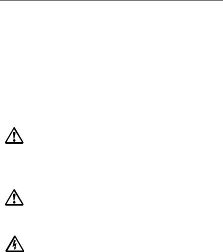
Protective Dust Covers
Protective covers have been attached on the SONAR, AUX and NMEA connectors on the rear of the A60. If you are not using one or more of these ports, please keep the cover attached to the connector to protect it from the elements.
Dust Cover
D8695-1
Important Information |
7 |
EMC Conformance
All Raymarine equipment and accessories are designed to the best industry standards for use in the recreational marine environment.
Their design and manufacture conforms to the appropriate Electromagnetic Compatibility (EMC) standards, but correct installation is required to ensure that performance is not compromised. Although every effort has been taken to ensure that they will perform under all conditions, it is important to understand what factors could affect the operation of the product.
The guidelines given here describe the conditions for optimum EMC performance, but it is recognized that it may not be possible to meet all of these conditions in all situations. To ensure the best possible conditions for EMC performance within the constraints imposed by any location, always ensure the maximum separation possible between different items of electrical equipment.
For optimum EMC performance, it is recommended that wherever possible Raymarine equipment and cables connected to it are:
At least 3 ft. (1 m) from any equipment transmitting or cables carrying radio signals e.g. VHF radios, cables and antennas. In the case of SSB radios, the distance should be increased to 7 ft. (2 m).
More than 7 ft. (2 m) from the path of a radar beam. A radar beam can normally be assumed to spread 20 degrees above and below the radiating element.
Ensure that the equipment is supplied from a separate battery from that used for engine start. Voltage drops below 10 V, and starter motor transients, can cause the equipment to reset. This will not damage the equipment, but may cause the loss of some information and may change the operating mode.
Ensure that Raymarine specified cables are used. Cutting and rejoining these cables can compromise EMC performance and must be avoided unless doing so is detailed in the installation manual.
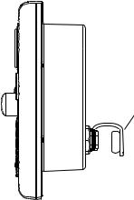
Suppression Ferrites
If a suppression ferrite is attached to a cable, this ferrite should not be removed. If the ferrite needs to be removed during installation it must be reassembled in the same position. If a ferrite is packed separately in the carton, it must be installed as soon as the cables are run.
8 |
A60 Installation Manual |
The following illustration shows typical cable suppression ferrites sometimes used with Raymarine equipment. To ensure EMC compliance, always use these ferrites, if supplied by Raymarine for use with this equipment. If not supplied by Raymarine, a ferrite is not required for use with this equipment.
Connections to Other Equipment
If your Raymarine equipment is to be connected to other equipment using a cable not supplied by Raymarine, the suppression ferrite (if supplied) MUST always be attached to the cable nearest the Raymarine unit.
Declaration of Conformity
Raymarine plc declare that the A60 Dual Function Displays are in compliance with the essential requirements of EMC directive 2004/108/EC. The original Declaration of Conformity certificate can be viewed on the relevant product page at www.raymarine.com.
Product Disposal
Waste Electrical and Electronic Equipment (WEEE) Directive
The WEEE Directive requires the recycling of waste electrical and electronic equipment. While the WEEE Directive does not apply to some of Raymarine’s products, we support its requirements as part of our environmental policy and we ask you to be aware of how you should dispose of this product.
The wheelie bin symbol found on our products signifies that it should not be disposed of in general waste or landfill. Please contact your local dealer, national distributor or Raymarine Technical Services for information on product disposal.

9
Chapter 1: Introduction
This manual provides information and instructions for installing your A60 display and RS12 GPS sensor.
1.1 Selecting the Display Unit Location
Your A60 can be mounted using the mounting bracket supplied, or console mounted using the optional flush mount kit.
Before you install the display, plan its installation, considering:
•Convenience. The mounting location should be easily accessible to allow operation of the front panel controls.
•Access. There must be sufficient space behind the display to allow cable connections to the rear panel connectors, avoiding tight bends in the cable.
•Interference. The selected location should be far enough away from devices that may cause interference, such as motors, generators and radio transmitters/receivers (see EMC Guidelines).
•Magnetic compass. Mount the display at least 3ft (1m) away from a magnetic compass.
•Cable runs. The display should be mounted as close as possible to the DC power source.
•Environmental. The display should be protected from physical damage and excessive vibration. Although the display unit is waterproof, it is good practice to mount it in a protected area away from prolonged and direct exposure to rain and salt spray.

10 |
A60 Installation Manual |
1.2 What Comes in the Box
Unpack the display carefully, to prevent damage. Save the carton and packing, in case the unit has to be returned for service.
Frame Screws,
M3 (x4)
A60 Dual Function Display, |
Mount Frame, |
E33025 (US), E33026 (CE) |
part no. R38109 |
Bracket Screws,
No.10 x 3/4 (x3)
Mounting Bracket,
part no. R38110
Sun Cover, part no. R38108
RS12 GPS, part no. E33021
GPS Antenna |
Thumb nuts (x2) |
GPS Gasket
Studs (x2)
Pole Mount Bracket |
Mount Screws, M4 (x2) |
Power/Data Cable, 3 pin, 1.5m part no. R08003
NMEA Cable, 5 pin, 1.5m part no. R08004
Bracket Knobs, part no. R38107
A60
Installation
Manual
Installation Manual,
part no. 87081
A60
Owner’s
Handbook
D9613-1
Owner’s Handbook,
part no. 81295
Chapter 1: Introduction |
11 |
1.3 Optional Equipment
The following optional items are also available to complete your system:
Part No. |
Description |
|
|
E63070 |
DSM25, Digital Sounder Module, 200/50KHz, 500W |
|
|
E36017 |
Flush Mount Kit, A60 |
|
|
R69086 |
Network Cable, A60, 3.5m |
|
|
E36015 |
Network Cable, A60, 8.5m |
|
|
E36016 |
Network Cable, A60, 15m |
|
|
E66066 |
Transducer Adapter, Pathfinder (DSM250) to A Series |
|
|
E66070 |
Transducer Adapter, Legacy Transducer (L365/L470) to A Series |
|
|

12 |
A60 Installation Manual |
1.4 Unit Size
The dimensions for your A60 display are as follows:
9.61in (244mm)
|
ENTER |
|
CANCEL |
|
RANGE |
|
PAGE |
|
ACTIVE |
|
WPTS |
|
MOB |
|
DATA |
PWR |
MENU |
9.88in (251mm) 11.02in (280mm)
2.56in 2.40in (61mm)  (65mm)
.866in (22mm)
6.81in
(173mm)
7.83in
(199mm)
D9614-1
3.11in |
3.43in |
(79mm) |
(87mm) |
Bracket Mount |
Flush Mount |
13
Chapter 2: Installing the Display Unit
The A60 display unit is waterproof to IPX-7 and can be installed either above or below deck using either the mounting bracket or by flush mounting into the console.
2.1 Mounting
Note: The mounting bracket and the mount frame to which the bracket attaches must be removed prior to flush mounting.
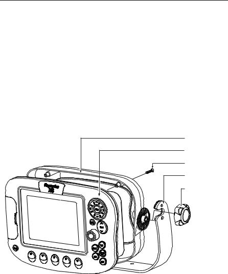
Mounting Bracket Method
The mounting bracket can be used to secure the display unit to a dash, chart table, bulkhead or deckhead.
Mount Frame
Display Unit
Frame Screws (x4)
Mounting Bracket
Bracket Knobs (x2)
D9615-1
You should install the mount bracket as follows:
1.Loosen the knobs and remove the bracket from the unit.
2.Mark the locations of the bracket screw holes on the mounting surface.
3.Drill 9/64” (3mm) pilot holes at the marked locations, taking care that there are no cables or anything that may be damaged behind the surface.
4.Align the bracket holes with the holes on the mounting surface.

14 |
A60 Installation Manual |
5.Use the screws and nuts supplied to securely attach the bracket to the mounting surface.
1 |
2 |
3 |
x3
x3
D7899-1
6.Attach the display unit to the bracket.
7.Adjust the unit angle for clear vision and tighten the knobs.
Flush Mounting
Flush mounting your display on the console requires the optional E36017 Flush Mount Kit.
D9616-1 |

Chapter 2: Installing the Display Unit |
15 |
CAUTION: Installation
Make sure there are no hidden electrical wires or other items behind the selected location before proceeding.
Make sure there is sufficient rear access for mounting and cabling.
1.Check the selected location for the unit. A clear, flat area with suitable clearance behind the panel, is required.
2.Attach the template included with the flush mount kit to the selected location, using masking or self-adhesive tape, taking care that it is level.
3.Use a hole saw to make a pilot hole in each corner of the cut-out area.
4.Using a suitable saw, cut along the inside edge of the cut-out line.
5.Detach the mount frame from the unit by removing the four mounting screws. Make sure that the unit fits in the area that has been cut out.
6.Drill four 3/16 in (4.5 mm) holes as indicated on the template to accept the retaining bolts.
7.Place the gasket onto the display unit.
8.Connect the cables to the display, avoiding tight bends.
9.Screw the 4 supplied studs into the rear of the unit.
10.Slide the unit into the console.
11.From the rear, attach the supplied nuts onto the studs and tighten until secure.
2.2 Cable Runs
When installing system cables consider the following:
•All cables should be adequately secured, protected from physical damage and exposure to heat. Avoid running cables through bilges or doorways, or close to moving or hot objects.
•Avoid acute bends.
•Where a cable passes through an exposed bulkhead or deckhead, a watertight feed-through should be used.
•Secure cables in place using tie-wraps or lacing twine. Coil any extra cable and tie it out of the way.
•Do not pull cables through a bulkhead or deckhead using a cord attached to the connector. This could damage the connections.
 Loading...