


Distributed by
Any reference to Raytheon or RTN in this manual should be interpreted as Raymarine. The names Raytheon and RTN are owned by the
Raytheon Company.
ST40 Bidata
Instrument
Owner’s
Handbook
Document number: 81159_2
Date: 1st May 2001
Copyright © Raymarine Limited 2001
Preface |
i |
Important information
WARNING
Although your ST40 instrument is designed to give accurate and reliable performance, it should serve only as an aid to navigation and should never lead to the erosion of good seamanship. Always maintain a permanent watch and be aware of situations as they develop.
EMC conformance
All Raymarine equipment and accessories are designed to the best industry standards for use in the leisure marine environment.
The design and manufacture of Raymarine equipment and accessories conform to the appropriate Electromagnetic Compatibility (EMC) standards, but correct installation is required to ensure that performance is not compromised.
Handbook information
To the best of our knowledge, the information in this handbook was correct when it went to press. However, the Raymarine policy of continuous product improvement may change product specifications without notice. Consequently, unavoidable differences may occur between the product and the handbook from time to time, for which Raymarine cannot accept liability.
ii |
ST40 Bidata Instrument Owner’s Handbook |

Preface |
iii |
Contents |
|
Important information .......................................................... |
i |
WARNING ......................................................................... |
i |
EMC conformance ............................................................. |
i |
Handbook information ....................................................... |
i |
Preface ..................................................................................... |
v |
Parts supplied ................................................................... |
vi |
Chapter 1: Operation ............................................................. |
1 |
1.1 Introduction ................................................................. |
1 |
Display ....................................................................... |
1 |
1.2 Operating procedures .................................................. |
2 |
Display action............................................................. |
2 |
Silencing alarms ......................................................... |
2 |
1.3 Alarms ......................................................................... |
7 |
Alarm indications ....................................................... |
7 |
Shallow alarm ........................................................ |
7 |
Deep alarm ............................................................. |
7 |
Anchor alarms ........................................................ |
7 |
Enabling/disabling alarms .......................................... |
8 |
Chapter 2: Maintenance and Fault Finding ........................ |
9 |
2.1 Maintenance ................................................................ |
9 |
Servicing and safety ................................................... |
9 |
Instrument................................................................... |
9 |
Transducer ................................................................ |
10 |
Cabling ..................................................................... |
10 |
2.2 Fault finding .............................................................. |
10 |
Preliminary procedures ............................................ |
10 |
Fixing faults .............................................................. |
10 |
Assistance ................................................................. |
13 |

iv |
ST40 Bidata Instrument Owner’s Handbook |
|
|
Chapter 3: Installation ......................................................... |
15 |
|
3.1 Planning your installation ......................................... |
15 |
|
EMC installation guidelines ..................................... |
15 |
|
Suppression Ferrites ........................................... |
16 |
|
Connections to Other Equipment ......................... |
16 |
|
Tools required .......................................................... |
16 |
|
Site requirements ...................................................... |
17 |
|
Transducers .......................................................... |
17 |
|
Instrument ............................................................ |
19 |
|
3.2 Procedures................................................................. |
20 |
|
Fitting transducers .................................................... |
20 |
|
Running transducer cable .................................... |
20 |
|
Connections to the instrument .................................. |
21 |
|
Stand-alone connections ...................................... |
22 |
|
SeaTalk connections ............................................ |
23 |
|
Fitting the instrument ............................................... |
23 |
|
Desktop Mounting Bracket .................................. |
25 |
|
3.3 Calibration requirement ............................................ |
26 |
|
Chapter 4: Calibration ......................................................... |
27 |
|
4.1 Introduction ............................................................... |
27 |
|
EMC conformance ................................................... |
27 |
|
4.2 User calibration ......................................................... |
27 |
|
Depth offsets ............................................................ |
31 |
|
4.3 Intermediate calibration ............................................ |
31 |
|
4.4 Dealer calibration ...................................................... |
32 |
|
Instrument Specification .................................................... |
35 |
|
Glossary ................................................................................. |
37 |
|
Index ...................................................................................... |
39 |

Preface |
v |
Preface
Thank you for purchasing a Raymarine product. We are sure your
ST40 instrument will give you many years of trouble-free operation.
This instrument is designed to provide reliable performance, even under the most demanding conditions.
-2 D4807
vi |
ST40 Bidata Instrument Owner’s Handbook |
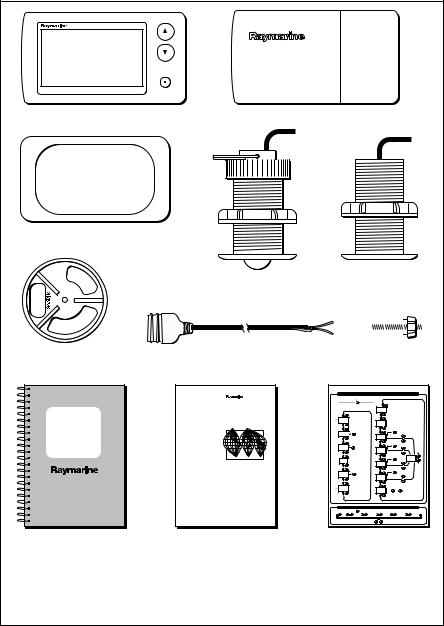
Parts supplied
ST40 BIDATA
ST40 Bidata instrument Instrument Cover
Gasket
Depth transducer
Retractable speed transducer Supplied with bung
(not illustrated)
|
|
|
|
|
|
|
|
|
|
|
|
|
|
|
|
|
|
|
|
|
|
|
|
|
|
|
|
|
|
Clamping bracket |
1 m (3 ft) |
power cable |
|
Fixing |
Thumb |
|||||||||
|
|
|
|
|
|
stud |
|
|
nut |
|||||
|
|
ST40 Bidata Instrument - quick reference guide |
|
|||||||
|
|
|
|
|
Normal operation |
|
|
|
||
|
|
|
SWITCH ON |
|
|
|
|
|
|
|
|
|
SPEED |
|
|
DEPTH |
|
|
|
|
|
|
|
Last permanent |
|
|
|
|
|
Notes: |
|
|
|
|
screen is displayed |
|
|
Depth |
|
|
|||
ST40 |
|
|
|
|
|
* denotes temporary screens |
||||
Worldwide |
|
|
|
|
|
|
which will time-out to the previous |
|||
|
|
|
|
|
|
permanent screen after 5 seconds. |
||||
Bidata |
Distributors |
Current |
|
|
|
Minimum |
On repeater instruments, on;ly the |
|||
speed |
|
|
|
Depth and Minimum depth |
||||||
|
|
|
|
|
|
Speed, Water temperature, |
||||
Instrument |
|
|
|
|
depth |
screens are available. |
||||
|
|
Reset |
|
|
|
|
Alarm on/off |
|
|
|
Owner's |
|
Maximum |
|
|
alarm |
3 seconds |
|
|
||
Handbook |
|
speed |
3 seconds |
|
|
Shallow |
|
|
||
|
|
Reset |
|
|
|
|
Alarm on/off |
|
|
|
|
|
Average |
|
|
|
|
3 seconds |
|
|
|
|
|
speed |
3 seconds |
|
|
Deep |
|
|
||
|
|
|
|
|
|
alarm |
|
|
+ |
|
|
|
|
|
|
|
|
|
|
|
|
|
|
|
|
|
|
|
|
Alarm on/off |
|
Set |
|
|
|
|
|
|
|
|
|
alarm |
|
|
|
Log |
|
|
|
Shallow |
3 seconds |
|
level |
|
|
|
|
|
|
|
|
- |
|||
|
|
|
|
|
|
anchor |
|
|
|
|
|
|
|
|
|
|
alarm |
|
|
|
|
|
|
|
Reset |
|
|
|
|
Alarm on/off |
|
|
|
|
Trip |
3 seconds |
|
|
Deep |
3 seconds |
|
|
|
|
|
|
|
|
anchor |
|
|
|
||
|
|
|
|
|
|
alarm |
|
|
|
|
|
|
Water |
|
|
|
|
|
With Set alarm level screen displayed, |
||
|
|
Temp. |
|
|
|
Offset |
and |
press the |
|
|
|
|
|
|
|
|
keys simultaneously |
||||
|
|
|
|
|
|
|
|
to save the alarm level and return to |
||
|
|
|
|
|
|
|
|
normal operation. |
||
|
|
|
Adjusting display backlighting/contrast |
|
|
|||||
|
|
To enter adjust mode, press |
for 1 second to adjust BACKLIGHTING and a further 1 second to adjust CONTRAST |
|||||||
|
|
OFF |
LEVEL 1 |
LEVEL 2 |
|
LEVEL 3 |
LEVEL 2 |
LEVEL 1 |
||
|
|
|
To exit adjust mode press |
or |
or wait for 5 second timeout |
|
||||
Owner’s Handbook. |
Worldwide Service Centre |
Quick Reference Guide |
Warranty document and fitting |
Handbook. |
|
templates included in Handbook |
|
|
Note:
The items shown here are supplied for an ST40 Bidata system. If an instrument is purchased separately, transducers are not included. If any item is not present, contact your Raymarine Dealer.
D4730-2
Chapter 1: Operation |
1 |
Chapter 1: Operation
1.1 Introduction
Your ST40 Bidata instrument:
•Provides speed information (current, maximum and average), in either knots (KTS), miles per hour (MPH) or kilometres per
hour (KPH).
•Provides log and trip information. These are given in either nautical miles (NM), statute miles (M) or kilometres (KM).
•Provides water temperature information. This is given in either degrees Celsius (°C) or degrees Fahrenheit (°F).
•Provides depth information in either feet (FT), metres (M) or fathoms (FA).
•Records the minimum depth encountered during the period it is switched on. You can reset this at any time.
•Enables you to define alarm thresholds for shallow water, deep water, shallow anchor and deep anchor.
•Enables you to see what offset is applied to the depth reading.
Note: The required speed, distance, depth and water temperature units are selected during User calibration (see Chapter 4, Calibration).
CAUTION
Your instrument is calibrated to factory (default) settings when first supplied and must therefore be calibrated before use, to ensure optimum performance on your vessel. Do NOT use the instrument until the calibration procedures have been satisfactorily completed, using the procedures in Chapter 4, Calibration.
Coloured bezel and Desktop Mounting Bracket options are available for your ST40 instrument. Contact your Raymarine dealer for further information.
Display
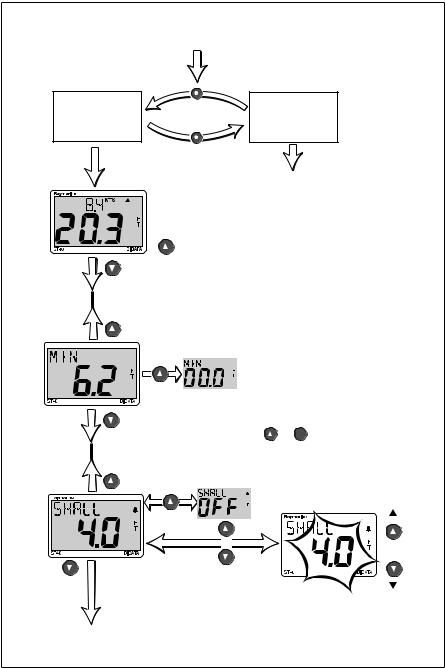
The ST40 Bidata display comprises upper and lower data areas, each of which shows either depth or speed information, selected as shown in the following illustration.
2 |
ST40 Bidata Instrument Owner’s Handbook |
DEPTH |
SPEED |
SPEED |
DEPTH |
Selecting where speed and depth information is displayed |
D4733-2 |
1.2 Operating procedures
Operating information is presented in flow chart form. The flow charts show the various operating screens and key presses necessary to carry out the various instrument functions. Key presses are momentary unless otherwise stated. Note that:
•Up/down depth-trend arrows are displayed, if the seabed is rising or falling at a significant rate.
•The minimum depth reading is reset to zero at power up.
•The maximum speed reading is reset to zero at power up.
•The average speed reading is reset to zero at power up.
•The Log screen shows the total distance covered by the vessel since the ST40 Bidata instrument was fitted.
•The trip reading is reset to zero at power up.
Display action
During normal operation (see Normal operation flow charts), the
Speed, Depth and Water temperature screens are permanent screens, i.e. once one of these is selected, it will remain until another screen is manually selected. All other screens are temporary and after 5 seconds, will time out to the permanent screen which was last displayed for 5 seconds or more.
Silencing alarms
To silence an alarm (see the Alarms section, later in this chapter), momentarily press any one of the instrument keys.

Chapter 1: Operation |
3 |
NORMAL OPERATION (sheet 1)
Switch on
DEPTH
SPEED
Previous speed screen is displayed
Current
speed Water temperature
Maximum |
Trip |
speed |
|
|
To reset |
|
3 seconds |
Average |
|
speed |
Log |
|
To reset |
|
3 seconds |
SPEED
DEPTH
See
NORMAL OPERATION
(sheet 2)
To reset
3 seconds
Note:
The trip distance can be reset only if the instrument is a speed master,
i.e. connected to a speed transducer.
Note: Screens annotated with * are temporary and will time-out to the previous permanent screen after 5 seconds.
D4731-2
4 |
ST40 Bidata Instrument Owner’s Handbook |
|
|
|
|
|
NORMAL OPERATION (sheet 2) |
|
|
Switch on |
|
SPEED |
DEPTH |
DEPTH |
SPEED |
See NORMAL OPERATION (sheet 1)
Depth
 To/from Offset screen (sheet 3)
Minimum depth 


To reset
3 seconds
Alarm
Shallow on/off alarm 

3 seconds
+
Momentary
If the Shallow alarm
has been locked during User calibration, you cannot switch it on or off or change the threshold value.
To/from
Deep alarm screen
(sheet 3)
Notes:
Note: Screens other than the Depth screen, are temporary and will time-out to the previous permanent screen after 5 seconds.
This diagram shows the operating sequence for an ST40 Bidata master instrument. On a repeater instrument, only the Depth, Minimum depth, Speed and Water temperature screens are available.
With any set alarm screen displayed, press the
and  keys simultaneously
to save the alarm level and return to normal operation.
Set Shallow alarm |
Increase |
|||
|
|
|
|
|
|
|
|
|
|
|
|
|
|
|
|
|
|
|
|
|
|
|
|
|
|
|
|
|
|
Decrease
D4732-2

Chapter 1: Operation |
5 |
NORMAL OPERATION (sheet 3)
To/from Shallow alarm screen (sheet 2)
Alarm Deep on/off alarm 


3 seconds
+
Momentary
Alarm
Shallow anchor on/off alarm 


3 seconds
+
Momentary
Alarm
Deep anchor on/off alarm 


3 seconds
Set Deep alarm
Set Shallow anchor alarm
Set Deep anchor alarm
+
Momentary
Offset
(+ve values)
(offset = 0.0)
(-ve values)
Increase
Decrease
Increase
Decrease
Increase
Decrease
To/from Depth screen |
|
|
(sheet 2) |
Note: Screens other than the Depth screen, are temporary and |
|
|
|
|
|
will time-out to the previous permanent screen after 5 seconds. |
D4734-2 |

6 |
ST40 Bidata Instrument Owner’s Handbook |
Adjusting display backlighting and contrast
Hold down  for 1 second to enter Adjust Backlight mode
for 2 seconds to move through Adjust Backlight mode and enter Adjust Contrast mode
ADJUST BACKLIGHTING
During normal operation, press for 1 second
The current backlighting level is displayed.
Select the required backlighting level then:
to adjust contrast, |
to return to normal operation, |
||
press |
for 1 second |
press |
or |
or wait for 5 second timeout
Normal operation
ADJUST CONTRAST
During normal operation, press for 2 seconds
via Adjust Backlighting
The current contrast level is displayed.
Select the required contrast level then press  or
or 
or wait for 5 second timeout
Normal operation
D4845-1

Chapter 1: Operation |
7 |
1.3 Alarms
Alarm indications
Shallow alarm
Depth is equal to or less than the shallow alarm threshold.
Alarm continues until cancelled manually.
D4666-2
Deep alarm
Triggered by depths equal to the deep alarm threshold. Continues until cancelled manually.
D4789_2
Anchor alarms
Depth is either:
equal to or less than the shallow anchor alarm threshold or
equal to or more than the deep anchor alarm threshold
D4790-2
 Loading...