


 Loading...
DSM300
Digital Sounder Module
Operation with hsb2 PLUS Series Displays
Document number: 81249-1
Date: November 2004
Trademarks and registered trademarks
Autohelm, HSB, Raymarine, RayTech Navigator, Sail Pilot, SeaTalk and Sportpilot are registered trademarks of Raymarine Limited. Apelco is a registered trademark of Raymarine Holdings Limited.(Registered in all Major marketing territories.)
AST, Autoadapt, Auto GST, Autoseastate, Autotrim, Bidata, Marine Intelligence, Maxiview, On Board, Raychart, Raynav, Raypilot, Raystar, ST40, ST60, Seaclutter, Smart Route, Tridata and Waypoint Navigation are trademarks of Raymarine Limited.
Navionics is a registered trademark of Navionics Company, Italy.
All other product names are trademarks or registered trademarks of their respective owners.
Software in this product is based in part on the work of the Independent JPEG Group.
Contents of this handbook ©Raymarine 2004

|
|
3 |
Contents |
|
|
Preface ..................................................................................................................... |
|
7 |
|
Purpose .................................................................................................. |
7 |
|
SAFETY NOTICE ...................................................................................... |
7 |
|
EMC Conformance ................................................................................. |
8 |
|
Conventions ........................................................................................... |
8 |
|
Technical Accuracy ................................................................................. |
8 |
Chapter 1: Overview ............................................................................................ |
9 |
|
1.1 |
Introduction ........................................................................................... |
9 |
|
General ................................................................................................ |
10 |
1.2 |
Fishfinder (Sonar) Mode Display Features ............................................ |
10 |
1.3 |
How to Use this Handbook ................................................................... |
10 |
Chapter 2: Getting Started ................................................................................ |
13 |
|
2.1 |
Introduction ......................................................................................... |
13 |
2.2 |
Powering on the Sounder Module ........................................................ |
13 |
|
Status LED ............................................................................................ |
13 |
2.4 |
Selecting Repeater Mode ..................................................................... |
15 |
2.5 |
Sonar Mode Display ............................................................................. |
16 |
2.6 |
Operating Modes ................................................................................. |
18 |
|
Horizontal Half-Screen Window Options .............................................. |
18 |
|
Vertical Half -Screen Window Options .................................................. |
18 |
|
Sonar Options ...................................................................................... |
19 |
|
Sounder Functions ............................................................................... |
20 |
2.7 |
Simulator Mode ................................................................................... |
21 |
|
Viewing Simulator Data ....................................................................... |
22 |
Chapter 3: System Setup ................................................................................... |
23 |
|
3.1 |
Introduction ......................................................................................... |
23 |
3.2 |
Changing the Set Up Parameters .......................................................... |
23 |
3.3 |
System Set Up Parameters .................................................................... |
25 |
|
Data Boxes ........................................................................................... |
27 |
|
Bearing Mode ...................................................................................... |
27 |
|
Cursor Reference .................................................................................. |
28 |
|
Cursor Readout .................................................................................... |
28 |
|
Day/Night ............................................................................................. |
28 |
|
Help ..................................................................................................... |
28 |
|
Soft Keys .............................................................................................. |
28 |
|
Key Beep .............................................................................................. |
29 |
|
MOB Data ............................................................................................ |
29 |
|
Autopilot Pop Up .................................................................................. |
29 |
|
Menu Timeout Period ........................................................................... |
29 |
|
Units .................................................................................................... |
29 |

4 |
DSM300 Operation with PLUS Series Displays |
|
|
Variation Source ................................................................................... |
30 |
|
Bridge NMEA Heading .......................................................................... |
31 |
|
NMEA-Out Set Up ................................................................................. |
31 |
|
Cursor Echo .......................................................................................... |
32 |
|
Date and Time Settings ......................................................................... |
33 |
|
GPS SOG/COG Filter .............................................................................. |
33 |
|
Compass Set Up ................................................................................... |
33 |
|
Language ............................................................................................. |
34 |
|
Simulator .............................................................................................. |
34 |
3.4 Sonar Set Up Parameters ...................................................................... |
34 |
|
|
Target Depth ID ..................................................................................... |
35 |
|
Color Bar .............................................................................................. |
35 |
|
Depth Digit Size .................................................................................... |
35 |
|
Sonar HSB Mode ................................................................................... |
35 |
|
Depth Offset ......................................................................................... |
36 |
|
Speed Calibrate .................................................................................... |
37 |
|
Temperature Calibrate .......................................................................... |
37 |
|
Sonar History ........................................................................................ |
37 |
|
Sonar Interference Rejection ................................................................ |
37 |
|
Sonar Simulator .................................................................................... |
38 |
|
Version/Serial Numbers ........................................................................ |
38 |
Chapter 4: Basic Display Controls .................................................................... |
39 |
|
4.1 |
Introduction .......................................................................................... |
39 |
|
Simulator .............................................................................................. |
39 |
4.2 Setting Color and Brightness ................................................................ |
39 |
|
|
Lighting and Contrast (Monochrome Displays) .................................... |
39 |
|
Brightness and Color Settings (Color Displays) ..................................... |
40 |
4.3 |
Controlling the Display ......................................................................... |
43 |
|
Switching Between Sounder and Other Modes .................................... |
49 |
4.4 |
Display Control Functions ..................................................................... |
50 |
|
Viewing Data Boxes .............................................................................. |
50 |
|
Changing the Scroll Speed .................................................................... |
51 |
|
Selecting the Power Setting .................................................................. |
52 |
|
Changing the Sounder Range ............................................................... |
53 |
|
Selecting the Frequency ........................................................................ |
54 |
|
Using Bottom Lock ............................................................................... |
55 |
|
Using Zoom .......................................................................................... |
59 |
Chapter 5: Sonar Mode Operation ................................................................... |
63 |
|
5.1 |
Introduction .......................................................................................... |
63 |
5.2 Interpreting and Adjusting the Sounder Image ..................................... |
64 |
|
|
Target Indications ................................................................................. |
64 |
|
Using White Line .................................................................................. |
65 |

|
|
5 |
|
Adjusting Display Gain (Sensitivity) ...................................................... |
65 |
|
Color Gain ............................................................................................ |
67 |
5.3 |
Using VRM ........................................................................................... |
70 |
5.4 |
Waypoints ............................................................................................ |
71 |
|
Placing a Waypoint .............................................................................. |
72 |
5.5 |
MOB ..................................................................................................... |
73 |
Appendix A: List of Abbreviations ................................................................... |
75 |
|
Index ......................................................................................... |
79 |
|
6 |
DSM300 Operation with PLUS Series Displays |

7
Preface
Purpose
Raymarine DSM300 Digital Sounder Modules provide echo sounder data that can be displayed on Raymarine E Series, C Series, and hsb2 PLUS (Pathfinder) Series display units. This handbook describes operating the DSM300 with hsb2 PLUS Series displays. Instructions for using the DSM300 with E Series and C Series displays are available in the handbooks for those products. The DSM300 will not work with older HSB (non-PLUS) displays.
DSM300 Digital Sounder Modules are intended for recreational depth finding and fishfinding purposes. Echo sounder systems require an appropriate Raymarine transducer unit and inter-connecting cable.
To obtain the best results in DSM300 operation and performance, please read this handbook thoroughly. Raymarine’s Technical Services representatives or your local dealer will be available to answer any questions you may have.
SAFETY NOTICE
This equipment must be installed and operated in accordance with the instructions contained in this manual. Failure to do so can result in personal injury and/or navigational inaccuracies. In particular:
CAUTION: High Voltage
The DSM300 contains high voltages. Adjustments require specialized service procedures and tools only available to qualified service technicians – there are no user serviceable parts or adjustments. The operator should never remove the cover or attempt to service the equipment.
CAUTION: Transducer Cable
Removing the transducer cable from the rear of the DSM300 while the sounder module is powered on can cause sparks. Only remove the transducer cable after power has been removed from the DSM300. As with any electronic device, be sure the sounder module is mounted where it is well ventilated and free from gasoline fumes.
If the transducer cable is accidentally removed while the DSM300 is powered on, remove power from the sounder module, replace the transducer cable, and then return power to the module. As a safety feature, the DSM300 only recognizes that the transducer is connected at power-up.
8 |
DSM300 Operation with PLUS Series Displays |
EMC Conformance
All Raymarine equipment and accessories are designed to the best industry standards for use in the recreational marine environment.
The design and manufacture of Raymarine equipment and accessories conform to the appropriate Electromagnetic Compatibility (EMC) standards, but correct installation is required to ensure that performance is not compromised.
Conventions
Throughout this handbook, the dedicated (labelled) keys are shown in bold capitals; for example, ENTER. The soft key functions, menu names and options are shown in normal capitals; for example, SCREEN.
Operating procedures, which may consist of a single key-press or a sequence of numbered steps, are indicated by a symbol in the margin. When the procedure requires you to press a soft key, the soft key icon is shown in the margin.
Technical Accuracy
To the best of our knowledge, the technical and graphical information contained in this handbook was correct as it went to press. However, the Raymarine policy of continuous improvement and updating may change product specifications without prior notice. As a result, unavoidable differences between the product and handbook may occur from time to time, for which liability cannot be accepted by Raymarine.
9
Chapter 1: Overview
1.1 Introduction
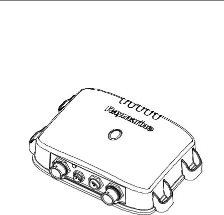
This handbook describes how to operate the DSM300 Digital Sounder Module with hsb2 PLUS (Pathfinder) Series displays. The DSM300 emits and receives sonar signals from a transducer mounted in the water, then interprets and transmits the data to a separate hsb2 PLUS (Pathfinder) Series display unit installed in your boat.
-1 D7462
Figure 1-1: DSM300 Digital Sounder Module
The DSM300 employs a very high transmission repetition or “ping” rate which, along with the digital adaptive high sample rate receiver, ensures that fish and bottom structure are presented in superb detail and optimal color allocation. The DSM300 digital bandwidth adaptation adjusts the receiver band width dynamically from very wide to very narrow, as required by the actual water conditions. This provides superior fish and bottom detection in all surroundings.
The DSM300 features dual frequency (200 kHz and 50 kHz) operation and— depending on the transducer installed and conditions—up to 1000 watts RMS output power and performance from 3 ft (1m) up to 5000 ft (1700 m).
Note: Many illustrations in this handbook show example screens. The screen you see on your display depends on your system configuration and set up options, so it may differ from the illustration.
10 |
DSM300 Operation with PLUS Series Displays |
General
The DSM300 system is comprised of the Digital Sounder Module, hsb2 PLUS (Pathfinder) Series display unit, transducer, and associated cables.
The DSM300 module is waterproof to IPX7 and can be installed either above or below deck.
The unit includes connections to:
•power
•the transducer
•hsb2 PLUS (Pathfinder) Series or C Series display unit
•E Series display unit
1.2Fishfinder (Sonar) Mode Display Features
When connected to a display unit and switched to Fishfinder (Sonar) mode, the following data can be viewed:
•Depth, speed and temperature, if the transducer is so equipped
•Single or split frequency sonar display: 50 kHz, 200 kHz
•Display options: zoom, bottom lock and A-Scope
•Windows to display additional data. (Position data requires GPS.)
1.3How to Use this Handbook
This handbook describes how to operate a DSM300 with your hsb2 PLUS (Pathfinder) Series display unit. Instructions for operating the DSM300 with
C Series or E Series displays are available in the handbooks for those products.
Chapter 2 shows how to start using the hsb2 PLUS (Pathfinder) Series display and viewing sonar echo data.
Chapter 3 provides instructions for setting up your PLUS Series display system to suit your preferences. You should read this chapter to determine how to change the sonar system from the default settings.
Chapter 4 details operating the PLUS Series display unit’s controls in Sonar mode.
Chapter 5 provides information for operating sonar functions using the PLUS Series display: selecting depth range limits, adjusting gain, color and STC, setting alarms, using the VRM marker, marks and man overboard.
Appendix A lists abbreviations used in this handbook.
Chapter 1: Overview |
11 |
Radome
DSM300
not used
Transducer
GPS
VHF Radio
 PLUS Display
RS-232
Interface Box
NMEA
SeaTalk
Power Supply
D7463-1
Figure 1-2: DSM300 in an Integrated System
12 |
DSM300 Operation with PLUS Series Displays |
Chapter 2: Getting Started |
13 |
Chapter 2: Getting Started
2.1 Introduction
This chapter provides basic instructions to get you started using the DSM300 Digital Sounder Module with a Raymarine hsb2 PLUS (Pathfinder) Series display. Instructions for operating the DSM300 with a C Series or E Series display are available in the handbooks for those products.
This chapter also describes Simulator mode and helps you to become familiar with the basic functions of the display’s controls in Sonar operation mode. More detailed information on using the controls and operating in Sonar mode is provided in Chapter 4 and Chapter 5, respectively.
Note: All settings described in this chapter are retained when the unit is powered off. However, there is a one-minute delay from the time you make the setting change to when the DSM300 places it in memory. If you power down the sounder less than one minute after making a change, the setting is lost.
2.2 Powering on the Sounder Module
There is no power switch on the DSM300. The unit turns on when the power cord is attached to boat’s power and plugged into the POWER connector on the connector panel.
CAUTION:
The DSM300 should be located so that the power cord can be easily removed, if necessary. If the sounder is placed in a difficult- to-reach location, Raymarine strongly suggests installing a power switch on the DSM300 power cord at a point where it is easily accessible.
Status LED
The LED on the front panel blinks green when the module is powered on and operating normally. If the unit detects a problem, the LED blinks amber to indicate a warning or red for an error. The number of times the LED blinks is a code representing the nature of the problem. For an explanation of the various error codes, refer to the DSM300 Installation Manual.
14 |
DSM300 Operation with PLUS Series Displays |
2.3 Selecting Sonar Mode
If properly connected to an hsb2 PLUS Series Radar, Chartplotter or Fishfinder display unit, you can begin viewing echo sounder data by setting the display to Sonar mode.
Note: Data, such as depth, speed, temperature, log, and trip are still available even if Sonar mode is not selected.
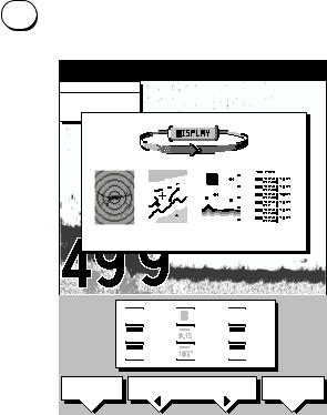
DISPLAY To set the mode, press the DISPLAY key to show the DISPLAY pop-up, then press again to cycle through the modes available, shown in Figure 2-1.
"DISPLAY" TO SELECT FULL SCREEN OPTION0 SOFTKEYS TO SELECT WINDOW OPTION
CURSOR |
0 |
||||||||||||||||||||||||
BRG |
099oR |
||||||||||||||||||||||||
|
|||||||||||||||||||||||||
RNG |
2.410nm |
|
|||||||||||||||||||||||
|
|
|
|
|
|
|
|
|
|
|
|
|
|
|
|
|
|
|
|
|
|
|
|
|
|
|
|
|
|
|
|
|
|
|
|
|
|
|
|
|
|
|
|
|
|
|
|
|
|
|
|
|
|
|
|
|
|
|
|
|
|
|
|
|
|
|
|
|
|
|
|
|
|
|
|
|
|
|
|
|
|
|
|
|
|
|
|
|
|
|
|
|
|
|
|
|
|
|
|
|
|
|
|
|
|
|
|
|
|
|
|
|
|
|
|
|
|
|
|
|
|
|
|
|
|
|
|
|
|
|
|
|
|
|
|
|
|
|
|
|
|
|
|
|
|
|
|
|
|
|
|
|
|
|
|
RADAR CHART SONAR LOG
|
|
|
|
|
ft |
60 |
||||||
|
|
|||||||||||
|
|
|
|
|
|
|
|
|
|
|
|
|
|
|
|
|
|
|
|
|
|
|
|
|
|
|
|
|
|
|
|
|
|
|
|
|
|
|
|
|
|
|
|
|
|
|
|
|
|
|
|
|
|
|
|
|
|
|
|
|
|
|
|
|
|
|
|
|
|
|
|
|
|
|
|
|
|
|
|
|
|
|
|
|
|
|
|
|
|
|
WINDOWS |
SELECT |
SPLIT |
|||
|
OFF |
ON |
WINDOWS |
HOR |
VER |
D6191-1
Figure 2-1: Using the DISPLAY Key
The selected mode is shown by an icon with a black (monochrome display) or red (color LCD) border and the mode is displayed on the screen.
When SONAR mode is shown (as in Figure 2-1), press ENTER or CLEAR. The default soft keys are displayed. The display shows the sounder screen.

Chapter 2: Getting Started |
15 |
2.4 Selecting Repeater Mode
DISPLAY
MENU
SONAR
SET UP¬
Depth data that is to be shared over the hsb2 network is sourced from the device that has been designated as the master sonar unit. Only a DSM300 or an hsb2 PLUS Series fishfinder display can be a master unit. For the DSM300 master to repeat its sonar image data to a display unit, the display must be designated as the REPEATER.
When using the DSM300 with a PLUS radar or chartplotter display, this is not an issue—the DSM300 is automatically set as the master and the display unit the repeater. However, the DSM300 can also repeat its image data on a fishfinder display. In this case, both units are capable of collecting sonar data. You must tell the display it is to be a repeater for the DSM300 and not a master unit on its own.
If your DSM300 is repeating its sonar data over a PLUS Series radar or chartplotter display, the proper settings are made automatically. You need do nothing else.
However, if your repeater display is a PLUS Series fishfinder, you must tell the unit to be a repeater.
To set the fishfinder display to be the sonar repeater:
1.Press the DISPLAY key until SONAR mode is selected, as described in the previous section.
2.Press the MENU key.
The Menu soft keys appear.
3.Press the SONAR SET UP soft key. The Sonar Set Up menu appears.
4.Press the trackpad until the SONAR HSB MODE parameter is highlighted (selected).
5.Press the REPEATER soft key.
6.Press ENTER.
The display unit is now designated as the Repeater.
Details on setting up your DSM300 and display are given in Chapter 3.
16 |
DSM300 Operation with PLUS Series Displays |
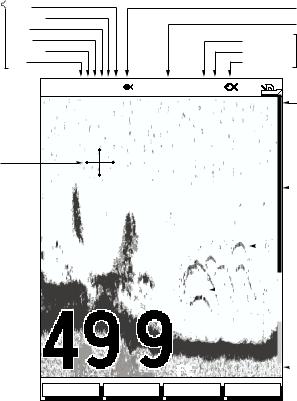
2.5 Sonar Mode Display
When you first switch the display unit into Sonar mode, the scrolling bottom graph is displayed. This is a graphical representation of the echoes seen by the DSM300. As time passes, this display scrolls from right to left and becomes a record of the echoes seen. A typical display is shown in Figure 2-2.
The images at the right hand side of the display are the most recent echoes. Some echoes indicate fish, and others show the bottom. It can also indicate bottom structures, such as a reef or shipwreck. The upper and lower depth range limits are shown.
The sonar screen includes a status bar that displays transducer frequency and indicates which auto settings are enabled (Gain, Color Gain, Range, Zoom and Frequency), and alarm status (fish and shallow/deep water depths).
You can customize the sounder by choosing what is displayed and how it is displayed (including language and units). For example, you can set the scroll speed of the bottom graph display, and you can select the range to adjust the depth displayed.
You can view the cursor position and a variety of data (such as speed and depth) from the transducer and other equipment in user-selectable data boxes. These data boxes can be moved around the screen and they can be switched on or off.
Chapter 4 includes details on adjusting the display; other set up options are described in Section 3.4.
Chapter 2: Getting Started |
17 |
|
Power |
|
Target Depth ID On |
Auto |
Frequency |
|
Frequency |
Zoom |
|
||
Mode |
|
|
|
Range |
Alarm enabled |
|
|
Indicators |
Alarm |
||
|
Color gain |
Shallow, Deep |
Indicators |
|
Gain |
Fish |
|
|
|
||
|
AUTO GCRZFH |
50kHz SD |
|
|
|
0 |
Water surface |
Cursor,
controlled
by trackpad
18
22 |
|
|
|
20 |
|
|
|
|
Depth markers |
|
|
|
|
|
|
|
|||||
|
|
|
|
|
|
|
|
|
|
|
|
|
|
|
32 |
|
|
|
|
|
|
|
35 |
33 |
37 |
|
|
|
|
|
Target image (fish arch) |
|
|
|
|
|
|
||||||
|
|
|
|
|
|
|
||||
|
36 |
36 |
|
|
|
|
|
|
||
38 |
|
|
|
|
|
|
|
|
|
|
42 |
|
|
40 |
|
|
|
|
Target image depth |
||
|
|
|
|
|
|
|
||||
|
|
|
|
|
|
|
|
|
||
|
|
|
|
|
|
|
|
|
|
|
Bottom depth 
|
|
|
ft |
60 |
|
Range |
|
|
|
|
|||
|
|
|
FREQUENCY ZOOM BTM.LOCK A-SCOPE
D6181-1
Figure 2-2: Typical Display in Sonar Mode

18 |
DSM300 Operation with PLUS Series Displays |
2.6 Operating Modes
Depending on the types of equipment you have connected, up to four full-screen modes – sonar, chart, radar, and data log are available. You select the operating mode using the DISPLAY key.
You can also set Windows On to split the display into two half-screen windows (horizontal or vertical) to show supplementary data, or to display sonar and chart or radar simultaneously.
Horizontal Half-Screen Window Options
Using horizontal half screens, the main operating mode is displayed in the upper window; you choose what is displayed in the lower window. The following information, if available on your system, can be shown:
Table 2-1: Horizontal Half-Screen Window Options
Full-screen |
|
mode |
Horizontal Half-Screen Window Options |
|
|
Sonar Mode |
Course Deviation Indicator (CDI), Bearing and Distance |
|
Indicator (BDI), Depth/Temp graph, Chart plotter, Radar |
|
|
Chart Mode |
CDI, BDI, Navigation Data (databoxes), Radar, Sonar |
|
|
Radar Mode |
CDI, BDI, Navigation Data, Chartplotter, Sonar |
|
|
Data Log Mode |
Half-screens not available |
|
|
Vertical Half -Screen Window Options
This option splits the sounder vertically. The left hand window displays data boxes; there are three different sets of data (A, B, and C) that you can select for display. The following information is available only in Sonar Mode:
Table 2-2: Vertical Half-Screen Window Options
Full-screen |
|
mode |
Vertical Half-Screen Window Options |
|
|
A |
Temperature, Speed, Depth |
|
|
B |
Position (latitude and longitude), Course Over Ground |
|
(COG), Speed Over Ground (SOG), Depth |
|
|
C |
Waypoint Range and Bearing, COG, SOG, Depth |
|
|
Note: Receiving and displaying position data requires a GPS connected to your system.

Chapter 2: Getting Started |
|
|
|
|
|
|
|
|
|
19 |
|||||||
Horizontal Half-Screen |
|
|
|
Vertical Half-Screen |
|
|
|
|
|||||||||
|
AUTO GCRZFH 50kHz |
|
|
|
|
AUTO GC FH |
50kHz |
|
|
|
|
||||||
|
|
|
|
|
0 |
|
TEMPERATURE |
|
0 |
|
|||||||
|
|
|
|
|
|
|
|
|
|
|
|
||||||
|
|
|
|
|
20 |
|
|
|
|
|
|
F |
|
|
|
|
|
|
|
|
|
|
|
|
|
|
|
|
|
|
|
|
|
||
|
|
|
|
|
|
|
|
|
|
|
|
|
|
|
|
|
|
|
|
|
|
|
|
|
|
|
|
|
|
|
|
|
|
|
|
|
|
|
|
|
|
|
|
|
|
|
|
20.1 |
|
|
|
|
|
|
|
|
|
|
40 |
|
|
|
|
|
|
15.1 |
|
20 |
|
|
|
|
|
|
|
|
|
|
|
|
|
|
|
|
|
|
|||
|
|
|
|
|
|
|
|
|
|
|
|
|
|
|
|
||
|
|
|
|
ft |
60 |
|
|
|
|
10.1 |
|
|
|
|
|
||
|
|
|
|
|
30 MINUTES |
0 |
|
|
|
|
|
||||||
|
|
|
|
|
XTE |
|
SPEED |
|
|
|
|
|
|
||||
|
|
|
|
|
|
|
|
|
|
|
|
|
|
|
|||
|
|
|
|
|
0.28nm |
|
|
|
|
|
|
|
|
|
|
||
|
|
|
|
|
|
|
|
|
|
|
|
|
|
|
|||
|
|
|
|
|
WPT BRG |
|
|
|
|
|
|
|
|
|
|
||
|
|
|
|
|
351°T |
|
|
|
|
kts |
|
40 |
|
|
|
||
|
|
|
|
|
|
|
|
|
|
|
|
|
|||||
|
|
|
|
|
WPT RNG |
|
|
|
|
|
|
|
|
|
|
||
|
|
|
|
|
|
DEPTH |
|
|
|
|
|
|
|||||
|
|
|
|
|
26.8nm |
|
|
|
|
|
|
|
|
|
|
||
|
|
STEER PORT |
TTG |
|
|
|
|
|
|
|
|
|
|
||||
|
|
03h:59m |
|
|
|
|
|
|
|
|
|
|
|||||
|
WAYPOINT 001 |
|
|
|
|
ft |
|
60 |
|
||||||||
|
|
|
|
|
|
|
|||||||||||
|
|
|
|
|
|
|
|
|
|
|
|||||||
FREQUENCY |
ZOOM |
BTM.LOCK |
A-SCOPE |
FREQUENCY |
ZOOM |
BTM.LOCK |
A-SCOPE |
D6206-1
Figure 2-3: Half-Screen Windows in Sonar Mode
Details on selecting windows are given in Chapter 4. For details on the radar, chartplotter or fishfinder display, please refer to the Owner’s Handbook supplied with that unit.
Sonar Options
The DSM300 provides controls to select additional modes:
•Frequency – you can select the transducer frequency: 50 kHz for wide coverage and deep water, 200 kHz for a detailed view, both frequencies simultaneously or auto-frequency. The default setting is auto-frequency, which determines the optimum frequency of operation based on the current depth.
•Bottom Lock – changes the operating mode to re-set the bottom. It provides a bottom-up view: the bottom is used as the reference, its image is flattened and depths are displayed here.
Bottom lock mode is used primarily to filter out the bottom structure and display fish details only.
•A-Scope – displays a real-time image of the bottom structure and fish directly below the transducer. The A-Scope window also displays the patented Bottom Coverage width indication.
•Zoom – enlarges all or part of the bottom graph display. You can select x2, x4, or x6 magnification and the zoom area can be automatically or manually adjusted.

20 |
DSM300 Operation with PLUS Series Displays |
You can select the Zoom or Bottom Lock image to be displayed in place of the regular bottom graph display. Alternatively, you can set the display window to be split vertically with the bottom graph displayed in the right hand screen and the Zoom or Bottom Lock image displayed in the left hand screen. See Figure 2-4.
If you choose dual frequency, the scrolling bottom graph is displayed in both frequencies, split horizontally. Zoom, Bottom Lock, or A-Scope can be displayed with the dual frequency graph.
All of these options are available when the sonar data is displayed in a half-screen window.
Sounder Functions
The DSM300 includes the following functions:
•Automatic or manual selection of scroll speed for bottom graph display
•Automatic or manual selection of transducer frequency
•Automatic or manual selection of depth range limits
•Automatic or manual selection of Gain, Color Gain, and STC settings
•Set up alarms for Fish, Shallow water and Deep water
•VRM marker to determine depth and distance
Operation of these functions is described in Chapter 4 and Chapter 5.
AUTO GC Z H SPLIT |
|
AUTO GC Z H SPLIT |
||||
0 |
0 |
|
||||
20 |
|
|
20 |
|
|
|
|
|
|
||||
40 |
40 |
60 |
60 |
200kHz |
80 |
|
200kHz |
80 |
6.8 |
|
|||||
50kHz |
0 |
|
50kHz |
0 |
|
20 |
20 |
40 |
|
40 |
|
|
|
||
60 |
|
|
|
|
60 |
|
|
|
|
|
ft |
|
80 |
|
ft |
80 |
27.2 |
FREQUENCY |
ZOOM |
BTM.LOCK |
A-SCOPE |
FREQUENCY |
ZOOM |
BTM.LOCK |
A-SCOPE |
Split Frequency |
Split Frequency with A-Scope |
Chapter 2: Getting Started |
21 |
AUTO GC Z H 200kHz
|
|
|
|
|
|
|
|
|
|
0 |
|
||
|
|
|
|
|
30 |
|
|
20 |
|
|
|||
|
|
|
|
|
|
|
|
|
|||||
|
|
|
|
|
20 |
|
|
|
|
||||
|
|
|
|
|
|
|
|
|
|||||
|
|
|
|
|
|
|
40 |
|
|
||||
|
|
|
|
|
|
|
|
|
|||||
|
|
|
|
|
10 |
|
|
|
|
||||
|
|
|
|
|
|
|
|
|
|||||
|
|
|
|
|
|
|
|
|
|
|
|||
|
|
|
|
|
|
|
|
|
|
|
|||
BL |
0 |
|
60 |
|
|
||||||||
|
|
|
|||||||||||
|
|
|
|
|
|
|
|
|
|||||
|
|
|
|
|
ft |
|
80 |
|
|||||
|
|
|
|
|
|
|
|||||||
|
|
|
|
|
|
|
|||||||
|
|
|
|
|
|
|
|
|
|
|
|
|
|
|
FREQUENCY |
|
|
ZOOM |
|
|
BTM.LOCK |
|
A-SCOPE |
||||
Bottom Lock Split with Bottom Graph
Figure 2-4: Sonar Display Options
2.7 Simulator Mode
AUTO GC Z H |
SPLIT |
|
|
|
|
|
||
|
|
|
55 |
0 |
||||
|
|
|
|
20 |
|
|
|
|
|
|
|
|
|
|
|
||
|
|
|
|
40 |
|
|
|
|
|
|
|
|
|
|
|
|
|
200kHz |
75 |
60 |
|
|
|
|
||
|
|
|
||||||
80 |
||||||||
50kHz |
55 |
0 |
||||||
|
|
|
|
20 |
|
|
|
|
|
|
|
|
|
||||
X4 |
|
40 |
|
|
|
|
||
|
|
|
|
|||||
|
|
|
|
|
|
|||
|
|
|
|
60 |
|
|
|
|
|
|
|
|
|
|
|
||
|
|
|
ft 75 |
80 |
||||
|
|
|
||||||
|
|
|
||||||
FREQUENCY ZOOM BTM.LOCK A-SCOPE
D6202-1
Zoom Split with Split Frequency
The DSM300 includes a simulator function that enables you to practice operating in Sonar Mode without data from the transducer.
Before using Simulator mode, make sure the display cable is connected from the DSM300 to the display unit and that both the DSM300 and display unit are connected to power.
If you have not fully installed the sonar module, you can still operate in Simulator mode by connecting the DSM to the display device. Then connect the DSM300 and the display unit to a 10.7–32VDC power supply, attaching the red wire from the power lead to positive (+) via a quick blow 8A fuse and the black wire to negative (–).
Figure 2-5 demonstrates how to setup the DSM300 for Simulator mode.

22 |
|
|
|
|
|
|
|
|
|
|
|
|
|
|
|
DSM300 Operation with PLUS Series Displays |
|||||||||||||||||
|
|
|
|
|
|
|
|
|
|
|
|
|
|
|
|
|
|
|
|
|
|
|
|
|
|
|
|
|
|
|
|
|
|
|
|
|
|
|
|
|
|
|
|
|
|
|
|
|
|
|
|
|
|
|
|
|
|
|
|
|
|
|
|
|
|
|
|
|
|
|
|
|
|
|
|
|
|
|
|
|
|
|
|
|
|
|
|
|
|
|
|
|
|
|
|
|
|
|
|
|
|
|
|
|
|
|
|
|
|
|
|
|
|
|
|
|
|
|
|
|
|
|
|
|
|
|
|
|
|
|
|
|
|
|
|
|
|
|
|
|
|
|
|
|
|
|
|
|
|
|
|
|
|
|
|
|
|
|
|
|
|
|
|
|
|
|
|
|
|
|
|
|
|
|
|
|
|
|
|
|
|
|
|
|
|
|
|
|
|
|
|
|
|
|
|
|
|
|
|
|
|
|
|
|
|
|
|
|
|
|
|
|
|
|
|
|
|
|
|
|
|
|
|
|
|
|
|
|
|
|
|
|
|
|
|
|
|
|
|
|
|
|
|
|
|
|
|
|
|
|
|
|
|
|
|
|
|
|
|
|
|
|
|
|
|
|
|
|
|
|
|
|
|
|
|
|
|
|
|
|
|
|
|
|
|
|
|
|
|
|
|
|
|
|
|
|
|
|
|
|
|
|
|
|
|
|
|
|
|
|
|
|
|
|
|
|
|
|
|
|
|
|
|
|
|
|
|
|
|
|
|
|
|
|
|
|
|
|
|
|
|
|
|
|
|
|
|
|
|
|
|
|
|
|
|
|
|
|
|
|
|
|
|
|
|
|
|
|
|
|
|
|
|
|
|
|
|
|
|
|
|
|
|
|
|
|
|
|
|
|
|
|
|
|
|
|
|
|
|
|
|
|
|
|
|
|
|
|
|
|
|
|
|
|
|
|
|
|
|
|
|
|
|
|
|
|
|
|
|
|
|
|
|
|
|
|
|
|
|
|
|
|
|
|
|
|
|
|
|
|
|
|
|
|
|
|
|
|
|
|
|
|
|
|
|
|
|
|
|
|
|
|
|
|
|
|
|
|
|
|
|
|
|
|
|
|
|
|
|
|
|
|
|
|
|
|
|
|
|
|
|
|
|
|
|
|
|
|
|
D7470-1
Figure 2-5: Simulator Mode Setup
Viewing Simulator Data
MENU
SONAR
SET UP¬
After you have properly connected and powered up the DSM300 and display units, you can toggle Simulator mode on and off using the Sonar Setup menu.
To view simulated sounder images:
1.Press the MENU key on display unit. The Setup soft keys appear.
2.Press the SONAR SET UP soft key.
The Sonar setup menu pop-up is displayed.
3.Use the trackpad to move the selection bar over the option SONAR SIMULATOR. The simulator soft keys are displayed.
4.Press the ON soft key to switch on the sonar simulator.
5.Press ENTER twice to return to the default display.
When simulator mode is on a simulator dialog box is displayed.
When the display is switched off then on again, simulator mode is maintained. It is recommended that you select the System Set Up Menu and switch off simulator mode when you have finished.
Note: Any waypoints placed on the chartplotter in simulator mode are retained in the database list and are available for use in routes.

23
Chapter 3: System Setup
3.1 Introduction
Once you have installed your DSM300 and are familiar with its basic operation (described in Chapter 1 and Chapter 2), you need to set it up so that it displays information according to your preferences.
Note: This chapter describes using the DSM300 Digital Sounder Module with a Raymarine hsb2 PLUS (Pathfinder) Series display. Instructions for setting up the DSM300 with a C Series or E Series display are available in the handbooks for those products.
This is achieved using the soft key controls that are displayed when you press the
MENU MENU key.
In most cases, you will only need to use the MENU key options when you first set up your system. As you become more familiar with your system, you may decide to customize some aspects, such as the screen and help setting.
Note: All settings described in this chapter are retained when the unit is powered off. However, there is a one-minute delay from the time you make the setting change to when the DSM300 places it in memory. If you power down the sounder less than one minute after making a change, the setting is lost.
This chapter covers the following topics:
•Changing the default set up parameters
•Sounder specific parameter functions and default settings
You should check the functions of the parameters and decide on the new settings before making the changes.
3.2 Changing the Set Up Parameters
The set up parameters are divided into two sections:
•System, to control the aspects of the system that are not specific to the sounder module.
•Sonar, to control the Sonar-mode display preferences, including HSB mode, calibration, and simulator.
This section provides instructions for displaying and changing the default values. The following sections list the parameters and their possible settings and describe the function of each parameter in turn.

24 |
DSM300 Operation with PLUS Series Displays |
To change settings:
1. Press the MENU key in Sonar mode to display the set up soft keys.
SYSTEM |
SONAR |
SCROLL |
TRIP |
SET UP¬ |
SET UP¬ |
SPEED |
RESET |
D5019-1
2.Press the soft key for the set up you desire.
The requested set up menu is displayed, listing the parameters and their current settings.
3.Use the trackpad to move the selection bar up and down the list. An arrow is displayed at the top or bottom right-hand corner if you can scroll the list to display further parameters.
As each line is highlighted, the soft keys are updated to show the settings available.
•For parameters that have a numeric value, or more than four possible settings, a scroll list is displayed above two of the soft keys.
•Some parameters are controlled by a slider that is displayed above two of the soft keys.
•For some parameters, a soft key provides access to a sub-menu of further options.
4.Press the soft key corresponding to the desired setting or, for scroll lists, use the soft keys to scroll forwards or backwards through the list until the desired setting is displayed. This setting is retained when you move the selection bar on to the next parameter in the menu list.
For sliders, press the appropriate soft key repeatedly to increase or decrease the slider value in individual steps, or press and hold the key to change the setting quickly.
5.Once you have set all the desired values, press ENTER to clear the menu and return to the set up soft keys.
6.Press ENTER, MENU, or CLEAR to clear the soft keys and return to the default display.

Chapter 3: System Setup |
25 |
3.3 System Set Up Parameters
SYSTEM SET UP¬
The SYSTEM SET UP option enables you to set up your system configuration and personal preferences.
The following table lists the System menus and their options, shows the factory default setting, and provides a space for you to make a note of your new setting. Each parameter is described in the following subsections.
Table 3-1: System Set Up Parameters
|
|
Factory |
New |
Menu |
Options |
Default |
Setting |
|
|
|
|
DATA BOXES |
|
|
|
POSITION |
OFF, LAT/LONG, or TDs |
OFF |
|
SPEED |
OFF or ON |
OFF |
|
DEPTH |
OFF or ON |
OFF |
|
COG |
OFF or ON |
OFF |
|
SOG |
OFF or ON |
OFF |
|
TIME |
OFF or ON |
OFF |
|
DATE |
OFF or ON |
OFF |
|
WIND |
OFF, APPARENT, TRUE, BOTH |
OFF |
|
WAYPOINT |
OFF, LAT/LON, RNG/BRG/TTG |
OFF |
|
CROSS TRACK ERROR |
OFF or ON |
OFF |
|
HEADING |
OFF or ON |
OFF |
|
LOG/TRIP |
OFF or ON |
OFF |
|
PILOT |
OFF or ON |
OFF |
|
VMG |
OFF, WIND, WPT, or BOTH |
OFF |
|
TEMPERATURE |
OFF or ON |
OFF |
|
TIDE SET/DRIFT |
OFF or ON |
OFF |
|
|
|
|
|
BEARING MODE |
MAGNETIC OR TRUE |
TRUE |
|
|
|
|
|
CURSOR REFERENCE |
MAG/TRUE or RELATIVE |
RELATIVE |
|
|
|
|
|
CURSOR READOUT |
OFF, LAT/LONG, RNG/BRG, or |
RNG/BRG |
|
|
BOTH |
|
|
|
|
|
|
DAY/NIGHT |
DAY/NIGHT |
DAY |
|
|
|
|
|
HELP |
OFF or ON |
ON |
|
|
|
|
|
SOFT KEYS |
OFF or ON |
ON |
|
|
|
|
|
KEY BEEP |
OFF or ON |
ON |
|
|
|
|
|
MOB DATA |
DR or POSITION |
DR |
|
|
|
|
|
PILOT POP-UP |
OFF or ON |
OFF |
|
|
|
|
|
Loading...