


Distributed by
Any reference to Raytheon or RTN in this manual should be interpreted as Raymarine. The names Raytheon and RTN are owned by the
Raytheon Company.

FishFinder L265
Instruction Manual
Raymarine

Contents
1
2
3
iv
Echo sounding – How it works (inside front cover) FishFinder L265 – Features and functions i
For information and service ii
Introduction 1 |
|
About the FishFinder L265 1 |
|
System Components |
2 |
Standard Equipment |
2 |
Standard Transducers |
2 |
Optional Accessories |
2 |
Installation 4
About the Transducer 4 |
|
Selecting the Correct Type of Transducer |
5 |
Assembling the Transducer Bracket 6 |
|
Positioning the Transom-Mount Transducer 7 |
|
Mounting the Transom-Mount Transducer |
9 |
Mounting the Optional Sidelooker Transducer 10 Installation Notes – Thru-Hull or Low-Profile Transducer 11 Installation Notes – In-Hull Transducer 13
Installation Notes – Trolling Motor Transducer |
13 |
|
Mounting the Display Unit – Standard Mount |
14 |
|
Dismounting the Display Unit |
15 |
|
Mounting the Display Unit – Flush Mount 15 |
|
|
Installing the Transducer Cable |
18 |
|
Installing the Transducer Cable – Sidelooker Option 20 Making the DC Power Connections 20
Operating Instructions 23
Controls on Display Unit |
23 |
||
Turning the Power On and Off 24 |
|||
Setup Memory |
24 |
|
|
Lamp/Contrast Menu 25 |
|||
Selecting Displays |
24 |
|
|
Operating Pages |
27 |
|
|
FishFinder Page |
|
28 |
|
Choosing a Frequency |
32 |
||
Fish Indications |
33 |
|
|
Bottom Indications |
35 |
|
|

4
5
6
Performance Modes 36
Zoom Page 37
A-Scope (Bottom Coverage) Page 39
Digital Page 41
Sidelooker Page 42
Setup Instructions |
46 |
|
|
||
The Setup Menu |
46 |
|
|
|
|
Range Setting |
47 |
|
|
|
|
Sensitivity Setting |
48 |
|
|
||
Chart Speed Setting |
49 |
|
|
||
Zoom Setting 50 |
|
|
|
|
|
Frequency Setting |
52 |
|
|
||
System Setup Display |
53 |
|
|
||
Simulator |
54 |
|
Deep Alarm |
55 |
|
Fish Symbol |
54 |
Fish Alarm |
56 |
||
White Line |
|
54 |
|
Buzzer 56 |
|
Sidelooker |
|
55 |
|
Depth Units |
57 |
Shallow Alarm |
55 |
|
|
||
Setup Instructions for Sidelooker 57 |
|
||||
Resetting the Unit to Factory Defaults 59 |
|
||||
Default Settings |
59 |
|
|
|
|
Maintenance and Troubleshooting 60 |
|
||||
Cleaning Instructions |
60 |
|
|
||
Troubleshooting Suggestions |
60 |
|
|||
How to Contact Raymarine |
64 |
|
|||
Specifications |
68 |
|
|
|
|
General Information |
68 |
|
|
||
FishFinder Functions |
69 |
|
|
||
Connector Diagrams |
70 |
|
|
||
Glossary of Terms |
71 |
|
|
||
Warranty 73 |
|
|
|
|
|
v

List of Figures
Figure |
Page |
|||
|
Unit in Use |
Inside front cover |
|
|
|
Front Panel |
i |
|
|
1-1 |
Typical Installation |
1 |
|
|
2-1 |
Transducer Types |
5 |
|
|
2-2 |
Assembling the Transducer Bracket |
6 |
|
|
2-3 |
Transducer Mounted on Transom |
7 |
|
|
2-4 |
Transducer Bracket, Side View |
7 |
|
|
2-5 |
Correct Mounting Position |
8 |
|
|
2-6 |
Mounting the Transducer |
8 |
|
|
2-7 |
Installing the Sidelooker Transducer |
10 |
|
|
2-8 |
Installing the Sidelooker Transducer on a Trolling Motor 14 |
|
|
|
2-9 |
Installation on Bracket |
15 |
|
|
2-10 |
Dimensions |
16 |
|
|
2-11 |
Flush-Mount Installation |
17 |
|
|
2-12 |
Disassembling from Bracket |
17 |
|
|
2-13 |
Installing Cable on Transom |
19 |
|
|
2-14 |
Cable for Sidelooker Transducer |
20 |
|
|
2-15 DC Power Connections |
21 |
|
||
3-1 |
Display Panel |
23 |
|
|
3-2 |
Lamp/Contrast Menu |
25 |
|
|
3-3 |
Selecting Display Pages |
26 |
|
|
3-4 |
FishFinder Page |
28 |
|
|
3-5 |
Fish Indications |
34 |
|
|
3-6 |
Bottom Conditions |
35 |
|
|
3-7 |
Zoom Page |
37 |
|
|
3-8 |
A-Scope Page |
39 |
|
|
3-9 |
Digital Page |
41 |
|
|
3-10 |
Sidelooker Feature |
42 |
|
|
3-11 |
Sidelooker Page |
43 |
|
|
4-1 |
Moving Through the Setup Menu |
46 |
|
|
4-2 |
Range Settings |
47 |
|
|
4-3 |
Sensitivity Setting |
48 |
|
|
4-4 |
Changing the Chart Speed Setting |
49 |
|
|
4-5 |
Chart Speed Setting |
50 |
|
|
4-6 |
Zoom Settings |
51 |
|
|
4-7 |
Frequency Setting |
52 |
|
|
4-8 |
Reaching the System Setup Display |
53 |
|
|
4-9 |
System Setup Display |
54 |
|
|
4-10 |
Sidelooker Range Settings |
58 |
|
|
4-11 |
Sidelooker Sensitivity Settings |
58 |
|
|
5-1 |
Sample Mailing Label |
67 |
|
|
6-1 |
Connectors |
70 |
|
|
vi
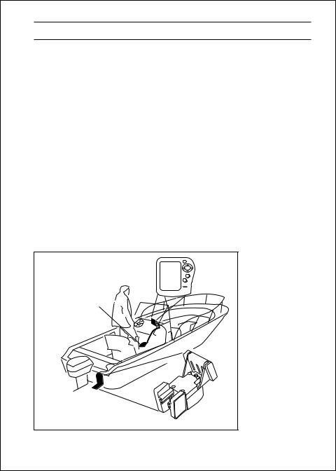
1 – Introduction
About the FishFinder L265
The FishFinder L265 is a system that uses sound waves (“sonar”) to detect fish and show the bottom of a lake or sea. The system includes a transducer and a display unit, connected by a cable. The transducer sends high-frequency sound waves down into the water. These sounds strike fish, the bottom, or other objects in the water, and return as echoes. The FishFinder then interprets these echoes and presents a display.
The FishFinder L265 can handle many different jobs:
•detect the presence of fish below the boat
•trigger an alarm when fish are found
•measure the depth of the water
•set alarms for minimum and maximum depth
•show the shape of the bottom
•determine whether the seabed is hard or soft
We are sure you will find the FishFinder L265 to be one of the most useful devices on your boat.
|
Raymarine |
FishFinder 265 |
|
Display Unit |
|
|
L265 |
Optional Thru Hull |
|
Transducer |
|
Transducer mounted |
|
in quick release |
Fig. 1-1 |
transom bracket |
|
|
Typical Installation |
Introduction |
1 |

System Components
The FishFinder L265 consists of a compact display unit connected to a transducer. The transducer is attached to the boat and extends into the water.
Standard Equipment
When you unpack your FishFinder L265, you should find the following standard equipment in the carton. If any items are missing, please notify your Raymarine dealer immediately, or contact the Customer Service Department at Raymarine at 1-800-539-5539, ext. 2333. Please provide the serial number of the FishFinder when reporting any missing items.
Description |
Part No. |
FishFinder L265 display unit |
|
(including attached yoke bracket) |
E61006 |
|
|
Quick-release swivel-mount bracket |
|
(with mounting hardware) |
M78945 |
|
|
DC power cable |
M99-146 |
|
|
Instruction manual |
G627295-2 |
|
|
10 x 3/4” ss mounting screws (qty. 4) |
- |
|
|
Standard Transducers
Depending on which model of the L265 you have purchased, the box will include one of the transducers listed below:
Description |
Part No. |
Transom-mount transducer (including |
|
mounting bracket and hardware) |
M78890 |
|
|
Low-profile thru-hull transducer (Valox plastic) |
M78922 |
|
|
Bronze thru-hull transducer |
M78921 |
|
|
Optional Accessories
Optional accessories and parts can be purchased directly from Raymarine. For prices and ordering information, please call the Parts Department at (800) 539-5539 ext. 2333.
2 |
Introduction |

Description |
Part No. |
Sidelooker transom-mount transducer |
M78930 |
|
|
Sidelooker transducer for trolling motor mounting. |
|
Companion with M78928 downlooker depth |
|
transducer, with 12 ft. (3.6 m) cable |
|
and hardware |
M78929 |
|
|
Extension for transducer cable (15 ft, 5 m) |
M99-140 |
|
|
Extension for transducer cable, |
|
for Sidelooker transducer (15 ft, 5 m) |
M99-139 |
|
|
Flush-mounting kit (with hardware and |
|
mounting template) |
M99-137 |
|
|
Fairing block for M78921 thru-hull transducer |
|
(Lexan plastic) |
M99-141 |
In-hull/trolling motor transducer (for installation in fiberglass hull only, or mounting on trolling motor,
including hardware for either installation) |
M78928 |
Angled in-hull transducer (for installation in |
|
fiberglass hull only, where deadrise angle is |
|
10° to 22°) |
M78946 |
|
|
Replacement transom-mount transducer |
|
mounting bracket kit |
M99-148 |
|
|
Soft storage/carrying case |
M99-114 |
|
|
Transducer switch box (select between two L265 |
|
FishFinder displays, using one transducer) |
M99-136 |
|
|
Introduction |
3 |

2 – Installation
The installation process has four parts:
•Mounting the transducer
•Mounting the display unit
•Connecting the cables for the transducer and power supply
•Calibrating the display unit
About the Transducer
Several different kinds of transducers can be used with this unit. The transom-mount style, used most often, and in-hull types are shown in Fig. 2-1. All of these transducers measure the water depth. An optional transducer, the Sidelooker, detects objects by looking out to the sides of the boat.
Since the transducer is very important to the operation of the FishFinder, it is vital that the transducer be mounted correctly. The transducer will give the most reliable readings if it looks into water which is smooth and undisturbed. If you place the transducer so bubbles or turbulence flow across the face of the unit, the system may give inaccurate readings.
There are three important rules when mounting any type of transducer:
•The transducer should be continuously covered by water when the boat is moving. (If the transducer is mounted near the side of the boat, it may be exposed when the boat is turning.)
•The transducer should be placed where turbulence or bubbles will not pass directly over the face of the unit. Don’t place the transducer behind any running strakes, intakes, or thru-hull fittings which create turbulence.
•The transducer should be mounted where it will not be affected by the wash from the propeller(s).
Selecting the Correct Type of Transducer
Before you begin the installation, double-check to be sure you have the correct type of transducer. Each kind of transducer is designed for a
4 |
Installation |
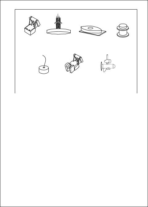
M78990 |
M78921 |
M99-141 |
M78922 |
Transom-mount |
Thru-hull |
Fairing for |
Low profile |
transducer |
transducer |
thru-hull transducer |
transducer |
M78946 |
M78930 |
M78928 |
In-hull |
Sidelooker |
Sidelooker |
transducer |
transducer |
transducer for |
|
|
trolling motor |
|
|
|
|
|
Fig. 2-1 |
|
|
Transducer |
|
|
Types |
particular type of use. In this manual we will include detailed mounting instructions for the transom-mount transducer. We will also include some general information on the other types. For detailed information on these other transducers, see the instructions which are packaged with the unit.
Use a transom-mount transducer if –
. . . your boat has an outboard or inboard-outboard engine(s), and if you’re planning to use the Sidelooker option. This type of transducer must be mounted ahead of or beside the propeller(s). Do not use this type of transducer for a boat with a straight-shaft inboard engine.
Use a thru-hull transducer if –
. . . your boat has a straight-shaft inboard engine. This type of transducer is installed in a hole drilled through the hull.
Installation |
5 |
Use a low-profile transducer if –
. . . you want minimum water resistance on a high-performance boat or sailboat. The bottom of the boat must be flat, or have a deadrise angle of no more than 10°.
Use an in-hull transducer if –
. . . you have a high-speed boat or if, for some reason, you cannot use a transom-mount or thru-hull transducer. The hull may be no more than 1" thick.
Use a trolling motor transducer if –
. . . you want to attach the transducer to a trolling motor. (Not recommended for deep-water operations.)
Use a Sidelooker transducer –
. . . for searching for fish or structure on either side of the boat. This type of transducer is attached to the bracket of the transom-mount transducer, or to the shaft of the trolling motor.
Assembling the Transducer Bracket
Fit together the two parts of the transducer bracket as shown in Fig. 2-2. When the installation is complete, the parts snap together as shown.
LIKE THIS! |
NOT THIS! |
Attach the |
Bracket is installed |
two parts |
upside down |
Lower the transducer and snap in the release clip
Fig. 2-2
Assembling
the Transducer
Bracket
6 |
Installation |
Allow a clearance of at least 10 inches (254 mm)
10" (254 mm)
Fig. 2-3
Transducer
Mounted on
Transom
Transducer in released position
Fig. 2-4
Transducer
Bracket,
Side View
Positioning the Transom-Mount Transducer
Begin by finding the best location for the mounting bracket. Here are the rules:
•If your boat has one propeller (outboard or inboard-outboard), mount the transducer about 18” (455 mm) to the side of the centerline of the boat. See Fig. 2-3. Choose the side that is on the downstroke of the propeller. (This is usually the starboard side of the boat.) This will reduce any interference caused by air bubbles.
Installation |
7 |
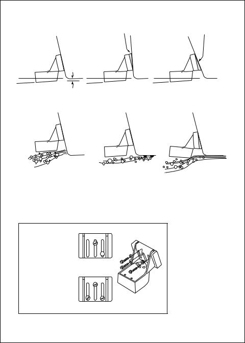
Average transom angle– |
Vertical transom – |
Sloping transom– |
no wedge necessary |
place wedge this way |
place wedge this way |
2 to 5 |
2 to 5 |
2 to 5 |
For fiberglass hull – 1/8" to 1/4" (3.2 to 6 mm)
For aluminum hull – 1/4" to 3/8" (6 to 9 mm)
No! |
No! |
No! |
The bow of the transducer |
Rivets on the hull are |
is above the bottom of the |
creating bubbles. |
transom, creating |
Lower the transducer |
cavitation. |
a bit. |
1 2 3
Insert screws 1 and 3 1/4" from the bottom of
slots, and screw 2 1/4" from the top of the
slot to allow room for 
 adjustment. Correct
alignment
If screws are inserted this way, it won’t be possible to make the height adjustment.
Incorrect alignment
8
The rear of the transducer is too high, creating cavitation.
Fig. 2-5
Correct Mounting
Position
Fig. 2-6
Mounting
the Transom-
Mount
Transducer
Installation

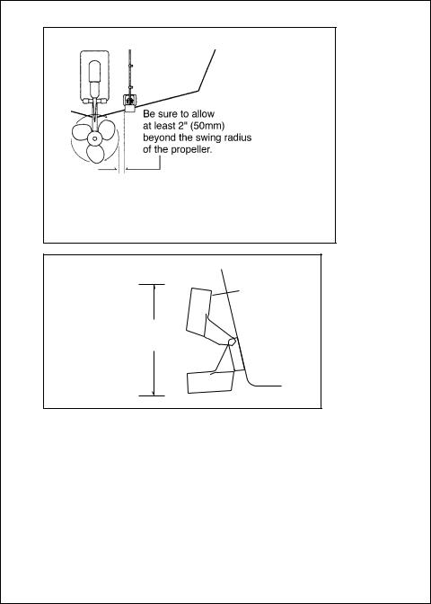
•If the propeller can be turned to steer the boat, allow at least 2" (50 mm) beyond the swing radius of the propeller. This will prevent the propeller from damaging the transducer when it is turned. After installation, check the clearance by turning the wheel so the propeller swings toward the transducer. There should always be a 2” (50 mm) clearance.
•If your boat has twin propellers (outboard or inboard-outboard), place the transducer near the centerline of the boat.
•Do not mount the transducer behind any hull fittings, intakes, or other parts which extend from the hull. These may cause turbulence or air bubbles.
•The bracket has a quick-release mechanism. This may reduce damage by allowing the transducer to flip up if it hits any debris or the bottom. See Fig. 2-4. Allow enough clearance above the transducer so that it can swing upward completely. This is about 10" (254 mm) measured from the bottom of the transom.
•If considering the Sidelooker option, look for a mounting location where the Sidelooker array will not be blocked by the engine housing or other mounted hardware.
•If the boat will be carried on a trailer, be sure the transducer will not hit any rollers, bunks or fittings on the trailer.
Mounting the Transom-Mount Transducer
1.On a boat with a fiberglass hull, the leading edge of the transducer should extend 1/8" (3.2 mm) to 1/4" (6 mm) below the bottom edge of the hull. See Fig. 2-5. On an aluminum hull, the transducer should extend a bit more – 1/4" (6 mm) to 3/8" (9 mm). If the boat will be operated at high speeds, the transducer may be mounted closer to the centerline of the hull.
2.The lower surface of the transducer should tilt down toward the rear at a slight angle (2° to 5°). The mounting bracket includes a wedge. Depending on the angle of the transom on your boat, you may need this wedge to get the correct angle for the bottom of the transducer.
3.Looking at the rear of the boat, be sure the bracket is vertical (perpendicular to the water line).
4.Hold the bracket (and the wedge, if used) against the transom and trace the positions of the screw slots.
Installation |
9 |

5.Remove the bracket. See Fig. 2-6. The screws in the outer slots should be placed about 1/4" (6 mm) up from the bottom of each slot. The screw in the center slot should be placed 1/4” (6 mm) down from the top. (This will allow you to adjust the bracket up or down a bit.) Drill pilot holes 3/4" (19.1 mm) deep. Use a 9/64" (3.6 mm) drill bit. To prevent drilling too deeply, wrap masking tape around the drill bit about 7/8" (22 mm) from the tip. Drill in only as far as the tape marker.
If you are attaching the bracket to a fiberglass hull, you can minimize any surface cracking of the gel coat. Before drilling each pilot hole, drill a shallow hole (chamfer) at each location about 1/16" (1.5 mm) deep. Use a 1/4" (6 mm) drill bit.
6.Attach the bracket to the hull using the panhead screws with flat washers. Before you tighten the screws, apply a good-quality marine sealant to the pilot holes. This will protect the hull from water penetration. Do not tighten the screws completely yet.
7.Move the bracket up or down so that the leading edge of the transducer has the clearance shown in Fig. 2-5.
8.Once the bracket is in the correct position, you can tighten the screws.
Mounting the Optional Sidelooker Transducer
1.The Sidelooker transducer allows the display unit to check the water to either side of the boat. This is helpful when you are looking for fish or structure near river banks, or under docks or piers.
2.The M78930 Sidelooker transducer is attached to the same mounting bracket used with the transom-mount transducer. See Fig. 2-7. Begin by installing the transom-mount bracket as described earlier.
3.Remove the two screws and brackets covering the paddlewheel.
4.Attach the Sidelooker transducer to the top of the transom mounting bracket. Use the four panhead screws supplied. The fit should be snug, but do not overtighten the screws.
5.Run the Sidelooker cable beside the depth cable for the transommount transducer.
10 |
Installation |
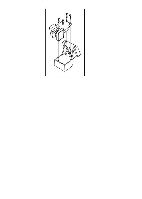
Fig. 2-7
Installing the
Sidelooker
Transducer
Installation Notes – Thru-Hull Transducer or Low-Profile Transducer
The installation process for these two types is almost the same. Detailed instructions for this installation will be included with the transducer. In this section, we will note just a few important points.
1.Earlier we listed three general rules for placing transducers. All of these rules apply when you are mounting a thru-hull or low profile transducer. Here are some other rules for selecting the best mounting location:
For planing hulls – Install in the flat planing area near the stern. Always install forward of the propeller(s) and shaft(s).
For small displacement hulls – Install near the centerline of the hull and 1/3 of the way forward from the stern. Always install forward of the propeller(s) and shaft(s).
For large displacement hulls – Install near the centerline of the hull and 1/3 of the way aft from the bow. Always install forward of the propeller(s) and shaft(s).
For sailboats – Install forward of the leading edge of the keel, to one side and near the centerline of the hull.
Installation |
11 |

2.Choose a location where you can easily reach the transducer from inside the boat. This will allow you to service the unit. Allow at least 6" (152 mm) of headroom above the transducer.
3.When choosing a mounting location, drill a small pilot hole (1/8" or 3.2 mm) from the inside of the hull. Before you drill the hole, be sure you will be able to reach the large nut on the top of the unit, and that there will be enough clearance for the cable. If there is a strake or other feature on the hull, drill from the outside of the hull instead. (This small hole can be filled easily if the mounting location is not suitable.)
4.The position of the transducer is especially critical on high speed boats (capable of more than 20 knots). Check the locations of the transducers on similar boats before installing the transducer in your own boat. Choose the location which will offer the best performance.
5.If the bottom of the hull at the mounting location is flat, you can mount the transducer directly through the hull. If the hull rises at an angle (the “deadrise angle”) of more than 10°, you must include a mounting block or “fairing.” The transducer must be mounted in a vertical position. Attach the fairing block to the hull as firmly as possible. This fairing block must be able to resist the drag of the water against the hull, and must also be completely waterproof.
6.If the hull of the boat has a core-type hull, you will need to follow some special mounting procedures. The core material must be protected from any water which may leak from the inside of the boat. (If the core material is allowed to remain wet, it may rot and weaken the hull.)
7.When working with the transducer, support it by holding the body of the unit. Do not hang the transducer from the cable.
8.It is very important to seal the opening around the transducer using a high-quality marine sealant suitable for underwater use. After installation, do not leave your boat in the water for any amount of time without checking for leaks.
12 |
Installation |

Installation Notes – In-Hull Transducer
Detailed instructions for this installation will be included with the transducer. In this section, we will note just a few important points.
1.Choose the best mounting location:
For outboard powerboats – Install as far aft as possible
For inboard/outboard powerboats – Install close to the engine(s)
For inboard powerboats – Install forward of the propeller(s) and shaft(s)
For sailboats – Install near the centerline of the hull and forward of the leading edge of the keel
2.An in-hull transducer may only be installed in a fiberglass hull which is no more than 1" (25 mm) thick. The in-hull transducer may not be installed in wood or aluminum hulls.
3.Use the standard in-hull transducer if it will be installed in a flat part of the hull, or a section with no more than 10° of deadrise. Use the angled in-hull transducer if the mounting location has up to a 22° of deadrise.
4.Do not try to compensate for the angle of the hull by fairing the epoxy adhesive on the face of the transducer.
5.Use the epoxy supplied with the in-hull transducer, or an equivalent epoxy glue. Do not use any other type of adhesive, including silicone or RTV adhesive.
Installation Notes – Trolling Motor Transducer
Both Downlooker and Sidelooker transducers may be installed on a trolling motor. See Fig. 2-8.
Detailed instructions for these installations will be included with the transducer(s). The Downlooker transducer is mounted on the horizontal gear case of the motor. The Sidelooker transducer is attached to the vertical support tube. These installations are simple, but it is important to keep these points in mind:
1.Keep the Sidelooker transducer fully submerged. The transducer will only produce an image if it is immersed in water.
2.Keep the Sidelooker transducer clear of weeds or debris.
3.When the position of the trolling motor is changed, the field of view of the Sidelooker also changes. The Sidelooker can be aimed at interesting echoes, but can also be positioned so that it is looking back at the hull. Be aware of the position of the Sidelooker transducer.
Installation |
13 |

Fig. 2-8
Installing the
Sidelooker
Transducer on a
Trolling Motor
Mounting the Display Unit – Standard Mount
You may mount the display unit on any flat surface using the bracket supplied. See Fig. 2-9. (There is also an optional kit which allows you to flush-mount the display in a flat panel or dashboard). Follow these instructions if you are using the standard mounting bracket:
1.The “LCD” type display used on this unit is easier to see from certain angles. Before selecting a permanent mounting location, make temporary power connections and turn on the unit. This will allow you to test the visibility of the display from several different angles.
2.Remove the display unit from the bracket by pressing on the large button in the center of the bracket. See Fig. 2-9.
3.Mount the base of the bracket using the supplied screws.
4.Slide the display unit back into the bracket.
5.Adjust the display unit for the best viewing angle. You can turn the display from side to side, and tilt it up or down.
14 |
Installation |

To release the display from the base, press on the right and left sides until you hear the clicks. Slide the display out of the bracket.
The display can be turned from side to side.
Raymarine
PWR
PAGE
SETUP
CLEAR
FISHFINDER L265 265
The angle of the display
can be changed.
Dismounting the Display Unit
Fig. 2-9
Installation on Bracket
See Fig. 2-9. To release the display from the bracket, press and hold down the left and right sides. You will hear an audible “click,” and the bracket will slide out.
Mounting the Display Unit – Flush Mount
In order to do this installation, you will need the optional flush mounting kit (part no. M78931). See Fig. 2-11.
1.Select a mounting location on the dashboard or control panel. Choose a clear, flat area at least 6" x 6" (152 mm x 152 mm). Be sure you will also have at least 6" (152 mm) of clearance behind the area where the display unit will be mounted. It is a good idea to drill a small pilot hole in the center of the mounting area. Be sure there are no hidden electrical wires or other items behind the point where you plan to mount the display unit.
2.A mounting template is supplied with the flush mounting kit. Tape this over the selected location on the panel and trace around the edges.
3.Make the cutout for the display. Drill a series of 1/2" (13 mm) holes at the points shown around the edges of the cutout area.
Installation |
15 |
Countersink |
2-25/32" |
3/8" (10 mm) |
(70 mm) |
Hole 3/16" (5 mm) |
|
|
2-21/32" |
2-23/32" |
(67 mm) |
(69 mm) |
|
1-13/32" |
|
(36 mm) |
5-7/32" (133 mm) |
|
|
63/64" |
|
(25 mm) |
6-3/4" |
|
|
|
(172 mm) |
|
5-9/32" |
1-3/4" |
(134 mm) |
(44 mm) |
|
4-9/32" |
|
(109 mm) |
|
|
3-29/32"(99 mm) |
|
4-7/32"(107 mm) |
|
Fig. 2-10 |
|
Dimensions |
16 |
Installation |

Gasket
Mounting hole cut according to template
Screw holes
Fasten with threaded studs and wing nuts
Fig. 2-11
Flush-mount
Installation
4.Drill the two small holes for the threaded studs as shown on the mounting template. Use a 7/32" (5.5 mm) drill bit.
5.Remove the template and draw straight lines between the 1/2" holes. Cut along each of the lines with a small saw.
Raymarine
PWR
PAGE
SETUP
CLEAR
FISHFINDER
L265
To pry up the cap insert a small screwdriver here
Installation
Fig. 2-12
Disassembling from Bracket
17

6.Separate the display unit from the mounting bracket. (See Fig. 2-12.) Press the large button in the center of the bracket to separate the bracket arms. The display unit is attached to the arms by two screws. Each screw is covered by a cap. Locate the small slot beside each cap and pry upward using a small screwdriver. Remove the caps, then the two screws and the two wave washers. Save these parts in case you ever want to use the mounting bracket.
7.Screw the threaded studs into the holes on the rear of the display unit.
8.Set the display unit into place to be sure that it will fit correctly. Thread the wing-nuts onto the threaded studs to hold the display unit in place temporarily.
9.Install the DC power wiring as described later in this section. Finally, finish the installation. Hold the gasket in place around the opening. Fit the display unit into the cutout. From the rear, screw the thumbscrews securely onto the threaded studs to hold the unit in place.
Installing the Transducer Cable
A 20 foot length of cable, with the connector attached, is supplied with the transducer. During the installation, do not cut the transducer cable or remove the connector. Do not try to shorten or splice the cable. The transducer cable includes several wires, along with shielding and insulation. If the cable is cut, it cannot be repaired. (Cutting the cable will also void the warranty.) During installation, if you need to drill any holes for the cable, they must be large enough to accept the connector. This will allow you to make the installation without cutting the wire.
1.Route the cable up and over the top edge of the transom. See Fig. 2- 13. Secure the cable using cable clamps. (These clamps are available from your local marine equipment supplier.)
If you do not want to expose the cable on the deck, you may drill a new hole (3/4" or 19 mm) through the transom for the cable. (Remember – this hole must be large enough to accept the cable with the connector attached. Do not cut the cable!) To seal the opening, use a feed-thru cap where the cable passes through the transom.
2.Run the cable through the interior of the boat. If the transducer cable runs near another electrical wire, it may pick up electrical interference or “noise.” To reduce this, try to keep the transducer cable separated
18 |
Installation |

as far as possible from all other wires. This is especially important with wiring for the boat’s ignition, alternator, or tachometer. Also try to keep the transducer cable away from the antenna and power cables for VHF or FM radios. It is also helpful to keep the transducer cable away from the FishFinder power cable. If it is necessary to run the transducer cable across any wires, make the crossing at a right angle.
3.Be careful not to tear the cable jacket when passing it through bulkheads and other parts of your boat. Secure the cables in place using tywraps or lacing twine. Coil the extra cable and tie it out of the way.
4.If the 20 foot (6 m) transducer cable is not long enough, a 15 foot (4.6 m) extension cable is available from your Raymarine dealer (part no. M99-140). When you attach the extension cable, be sure that the connections are tight and watertight. Use Dow Corning DC-4 or an equivalent sealing compound to protect the connector assemblies. Note: To extend both depth and Sidelooker cables, use the M99-139 extension cable.
5.At the rear of the display unit, plug in the transducer cable using the keyed connector.
Cable feed-thru cap
Cable clamp
1" (25 mm)
Hull projections
Fiberglass: 1/4" (6mm)
Aluminum: 1/2" (13 mm)
Fig. 2-13
Installing Cable on Transom
Installation |
19 |
 Loading...