


 Loading...
Ray54E
Marine
VHF Radio
Owner’s Handbook
Document number: 81232-3
Date: July 2005

iii
About this Handbook
Introduction
This handbook describes the Ray54E fixed VHF marine radio. The Ray54E provides two-way communications on all International marine channels, pre-set private channels, and (if programmed) all US and Canadian and marine channels. The Ray54E includes equipment for Class “D” Digital Selective Calling (DSC).
Conventions Used
Throughout this handbook, the dedicated (labelled) keys are shown in bold capitals (for example: SCAN/SAVE). The LCD indicators and functions are shown in normal capitals (for example: TX).
Operating procedures, which may consist of a single key-press or a sequence of numbered steps, are indicated by an arrow icon shown in the margin.
Technical Accuracy
To the best of our knowledge, the information in this handbook was correct as it went to press. However, our policy of continuous product improvement and updating may change specifications without prior notice. As a result, unavoidable differences between the product and handbook may occur from time to time. Raymarine cannot accept liability for any inaccuracies or omissions it may contain.
For the latest product information visit our website: www.raymarine.com
Warranty
To register your new Raymarine product, please take a few minutes to fill out the warranty registration card found at the end of this handbook. It is very important that you complete the owner information and return the card to the factory in order to receive full warranty benefits.
Raymarine is a registered trademark of Raymarine plc.
© Raymarine plc 2005

iv |
Ray54E VHF Radio |
|
|
Important Information
Maritime Mobile Service Identity (MMSI)
The Ray54E includes equipment for Class “D” Digital Selective Calling (DSC). A nine-digit Maritime Mobile Service Identity (MMSI) number is required to operate the DSC equipment. In some areas, a radio operator licence is required before an MMSI number will be issued.
Note: You can request an MMSI number fromsame agency that issues radio or Ship Radio licences in your area. Once obtained, you can program the MMSI number into your Ray54E as described in this handbook.
Group MMSI ID
A Group ID MMSI number can also be entered for vessels that are part of a group, such as a flotilla or racing fleet, enabling DSC communications within the group.
Automatic Transmitter Identification System (ATIS)
If you purchased your Ray54E to include use on the inland waterways of the contracting governments of the “Regional Arrangement Concerning the Radiotelephone Service on Inland Waterways”— also known as the Basel Agreement1— your Ray54E will be programmed by your dealer to include Automatic Transmitter Identification System (ATIS) functionality. ATIS includes data at the end of radio transmission that identifies your station. ATIS operation can be turned on or off as needed via the radio’s Menu mode.
Note: When ATIS is enabled, certain programming steps have been implemented to protect the integrity of the Basel Agreement, including the blocking of DSC functions when ATIS is active. See Digital Selective Calling (DSC) on page 31 and ATIS Function on page 79.
Your ATIS ID number is derived from your vessel’s call sign. Your authorized Raymarine dealer can assist you in decoding your ATIS ID number, which you can then program into your Ray54E using the operation described on page 77.
1.The Basel Agreement includes Germany, Austria, Belgium, Bulgaria, Croatia, France, Hungary, Luxembourg, Moldova, the Netherlands, Poland, Romania, Russian Federation, the Slovak Republic, Switzerland, the Czech Republic, Ukraine and the Federal Republic of Yugoslavia.

v
SAFETY NOTICE
Your Raymarine VHF radio generates and radiates radio frequency (RF) electromagnetic energy (EME). This equipment must be installed and operated in accordance with the instructions contained in this handbook. Failure to do so can result in personal injury and/or product malfunction.
CAUTION: Navigation Aid
This unit is only an aid to navigation. Its accuracy can be affected by many factors, including equipment failure or defects, environmental conditions, and improper handling or use. It is your responsibility to exercise common prudence and navigational judgments. Do not reply upon this radio as a substitute for such prudence and judgment.
Antenna Mounting and EME Exposure
For optimal radio performance and minimal human exposure to radio frequency electromagnetic energy, make sure the antenna is:
•connected to the radio before transmitting
•located where it will be away from people
•located at least 1.5 metres (5 feet) from the radio’s main unit
Safe Compass Distance
Safe Compass Distance is 1 meter for a common mechanical compass; other compass types may require greater distances. To be sure, you should locate the radio as far as possible from the compass. Test your compass to verify proper operation while the radio is also operating.
EMC Conformance
All Raymarine equipment and accessories are designed to the best industry standards for use in the recreational marine environment. Their design and manufacture conform to the appropriate Electromagnetic Compatibility (EMC) standards but correct installation and use is required to ensure that performance is not compromised.
Product Disposal
When you want to dispose of this product at the end of its working life, please do so in accordance with local regulations.

vi |
|
|
Ray54E VHF Radio |
|
|
|
|
|
|
|
|
|
|
|
|
|
|
|
|
|
|
|
|
|

|
|
vii |
Contents |
|
|
About this Handbook ........................................................................................... |
iii |
|
Introduction ............................................................................................. |
iii |
|
Conventions Used ................................................................................... |
iii |
|
Technical Accuracy ................................................................................. |
iii |
|
Warranty .................................................................................................. |
iii |
|
Important Information ........................................................................................ |
iv |
|
Maritime Mobile Service Identity (MMSI) ............................................. |
iv |
|
Automatic Transmitter Identification System (ATIS) ............................. |
iv |
|
SAFETY NOTICE ................................................................................... |
v |
|
Product Disposal ....................................................................................... |
v |
|
Chapter 1: Introduction ....................................................................................... |
1 |
|
1.1 |
Ray54E Fixed Station VHF Radio ................................................... |
1 |
1.2 |
Features ............................................................................................ |
1 |
Chapter 2: Installation ......................................................................................... |
3 |
|
2.1 |
Unpacking and Inspection ................................................................ |
3 |
|
Equipment Supplied ..................................................................... |
3 |
2.2 |
Planning the Installation ................................................................... |
4 |
|
Typical Mounting Methods .......................................................... |
4 |
|
Flush Mounting ............................................................................. |
4 |
2.3 |
Power Connections .......................................................................... |
6 |
2.4 |
External Speaker Connections ......................................................... |
7 |
2.5 |
Grounding ........................................................................................ |
7 |
2.6 |
GPS/NMEA Data ............................................................................. |
7 |
2.7 |
Antenna Connections ....................................................................... |
8 |
Chapter 3: Getting Started .................................................................................. |
9 |
|
3.1 |
Keypad and Rotary Knobs ............................................................... |
9 |
|
Microphone Keys ....................................................................... |
10 |
|
Main Unit Rotary Keys ............................................................... |
10 |
|
Main Unit Push Keys .................................................................. |
10 |
|
Microphone ................................................................................ |
11 |
|
1. PTT .................................................................................... |
11 |
|
2. UP/DOWN ........................................................................ |
11 |
|
3. 16/PLUS ............................................................................ |
11 |
|
4. HILO ................................................................................. |
11 |
|
Main Unit .................................................................................... |
11 |
|
5. CH ..................................................................................... |
11 |
|
6. PWR/VOL ........................................................................ |
11 |
|
7. SQ ..................................................................................... |
11 |
|
8. DW/TRI ............................................................................ |
11 |

viii |
|
Ray54E VHF Radio |
|
|
9. CALL/MENU ................................................................... |
|
12 |
|
10. HILO/USER ................................................................... |
|
13 |
|
11. SCAN / SAVE ................................................................. |
|
13 |
|
12. 16/PLUS .......................................................................... |
|
14 |
|
13. CLEAR ........................................................................... |
|
14 |
|
14. DISTRESS ...................................................................... |
|
14 |
3.2 |
LCD Display .................................................................................. |
|
14 |
|
1. (HI/LO) TX Power .................................................................. |
|
14 |
|
2. (TX) Transmitting ................................................................... |
|
14 |
|
3. (RX) Receiving ....................................................................... |
|
15 |
|
4. (LOCAL) Local/Distant Mode ............................................... |
|
15 |
|
5. DSC Message ......................................................................... |
|
15 |
|
6. ATIS Active ............................................................................ |
|
15 |
|
7. NO GPS ................................................................................... |
|
15 |
|
8. Battery Low ............................................................................ |
|
15 |
|
9. (USER) Favourite Channel Mode ........................................... |
|
15 |
|
10. (SAVED) Memory Mode ...................................................... |
|
15 |
|
11. (WX) Weather Channel ......................................................... |
|
15 |
|
12. (ALERT) Weather Alert ........................................................ |
|
15 |
|
13. (U I C) Channel Set ............................................................... |
|
16 |
|
14. (A) Simplex Channel ............................................................ |
|
16 |
|
15. (B) Receive-only Channel .................................................... |
|
16 |
|
16. Channel Number ................................................................... |
|
16 |
|
17. Dot Matrix Display ............................................................... |
|
16 |
Chapter 4: General Operations ......................................................................... |
|
17 |
|
4.1 |
Turning the Power ON and OFF ..................................................... |
|
17 |
4.2 |
Setting the Volume ......................................................................... |
|
17 |
4.3 |
Setting the Squelch ......................................................................... |
|
17 |
4.4 |
Setting the Power Output ................................................................ |
|
17 |
4.5 |
Setting the Channel ........................................................................ |
|
18 |
|
On the microphone... ............................................................. |
|
18 |
|
On the main unit... ................................................................. |
|
18 |
4.6 |
Selecting a Weather Channel (If Available) ................................... |
|
19 |
|
Weather Alert Operation (If Available) ................................. |
|
20 |
4.7 |
Selecting the Priority Channel ........................................................ |
|
20 |
4.8 |
Selecting the Secondary Priority (PLUS) Channel ........................ |
|
21 |
|
Reprograming the Secondary Priority (PLUS) Channel ............ |
22 |
|
4.9 |
Transmitting ................................................................................... |
|
23 |
4.10 Using the Scan Modes .................................................................... |
|
23 |
|
|
All Scan ....................................................................................... |
|
24 |
|
Saved (Memory) Scan ................................................................ |
|
24 |
|
Priority All Scan ......................................................................... |
|
25 |

|
|
ix |
|
Priority Saved Scan ..................................................................... |
25 |
4.11 Adding Channels to Memory ......................................................... |
26 |
|
4.12 Using the Monitor Modes ............................................................... |
27 |
|
|
Dual Watch ................................................................................. |
27 |
|
Tri Watch ..................................................................................... |
28 |
4.13 USER Channel Mode ..................................................................... |
29 |
|
4.14 DSC Call Operation ....................................................................... |
29 |
|
4.15 Menu Mode Operation ................................................................... |
30 |
|
Chapter 5: Digital Selective Calling (DSC) ....................................................... |
31 |
|
5.1 |
DSC Call Function ......................................................................... |
32 |
5.2 |
Individual Calls .............................................................................. |
34 |
|
Making DSC Calls to Coast Stations .......................................... |
34 |
|
Transmitting an Individual Call .................................................. |
34 |
|
Receiving Individual Calls ......................................................... |
37 |
5.3 |
Group Calls .................................................................................... |
38 |
|
Transmitting a Group Call .......................................................... |
38 |
|
Receiving Group Calls ................................................................ |
40 |
5.4 |
All Ships Calls ................................................................................ |
42 |
|
Transmitting an All Ships Call .................................................... |
42 |
|
Receiving an All Ships Call ........................................................ |
43 |
5.5 |
Distress Calls .................................................................................. |
45 |
|
Sending a Distress Call ............................................................... |
45 |
|
Undesignated (Quick) Distress Call ..................................... |
46 |
|
Designated Distress Call ....................................................... |
46 |
|
Cancelling a Distress Call Made in Error .................................... |
48 |
|
Receiving a Distress Call ............................................................ |
48 |
|
Receiving a Distress ACK Sent from a Coast Station ................. |
49 |
|
Receiving a Distress Relay Sent by Another Station .................. |
49 |
5.6 |
Position Request ............................................................................. |
50 |
|
Specifying the Target Vessel ....................................................... |
50 |
|
Retrieving the Last Received Position Data ............................... |
52 |
|
Receiving a Position Request From Another Station ................. |
53 |
5.7 |
Call Log .......................................................................................... |
53 |
|
Making a Call from a Call Log Entry .......................................... |
54 |
|
Saving an MMSI ID Number from a Call Log Entry .................. |
55 |
5.8 |
DSC Distress Log ........................................................................... |
56 |
Chapter 6: Menu Settings .................................................................................. |
57 |
|
6.1 |
Menu Function ............................................................................... |
57 |
6.2 |
DSC Phonebook ............................................................................. |
59 |
|
Adding an Entry .......................................................................... |
59 |
|
Editing an Existing Entry ............................................................ |
61 |
|
Deleting an Existing Entry .......................................................... |
62 |

x |
|
Ray54E VHF Radio |
6.3 |
Backlight Adjustment .................................................................... |
63 |
6.4 |
Contrast Adjustment ....................................................................... |
63 |
6.5 |
GPS/Time Setup ............................................................................. |
64 |
|
When GPS Information Not Available ................................. |
64 |
6.6 |
Settings ........................................................................................... |
66 |
|
Latitude/Longitude Display ........................................................ |
67 |
|
Time Display ............................................................................... |
67 |
|
Time Offset ................................................................................. |
68 |
|
Time Format ................................................................................ |
68 |
|
COG/SOG Display ..................................................................... |
68 |
6.7 |
Radio Setup .................................................................................... |
69 |
|
Band ............................................................................................ |
69 |
|
Channel (CH) Name ................................................................... |
70 |
|
Display Name ....................................................................... |
70 |
|
CH Info ................................................................................. |
70 |
|
Deleting a Channel Name Entry ........................................... |
70 |
|
Ring Volume ............................................................................... |
70 |
|
Key Beep ..................................................................................... |
70 |
6.8 |
DSC Setup ...................................................................................... |
71 |
|
My MMSI ID .............................................................................. |
72 |
|
Group MMSI Setup .................................................................... |
73 |
|
Adding a New Group ............................................................ |
74 |
|
Editing an Existing Entry ...................................................... |
76 |
|
My ATIS ID ................................................................................ |
77 |
|
ATIS Function ............................................................................. |
79 |
|
Position Reply ............................................................................. |
81 |
|
Automatic Channel Changing for Incoming Calls ..................... |
82 |
6.9 |
Resetting Factory Defaults ............................................................. |
84 |
Chapter 7: Customer Service ............................................................................ |
85 |
|
7.1 How to Contact Raymarine ............................................................ |
85 |
|
Appendix A:Specifications ................................................................................. |
87 |
|
Appendix B:Channel List ..................................................................................... |
89 |
|
|
International Marine VHF Channels & Frequencies.................. |
89 |
|
European Private Channels and Frequencies .............................. |
92 |
|
WX Channels (North America only) .......................................... |
92 |
|
U.S. Marine VHF Channels and Frequencies............................. |
93 |
|
Canadian Marine VHF Channels and Frequencies .................... |
96 |
Appendix C:Glossary ......................................................................................... |
101 |
|
Index ................................................................................................ |
103 |
|
Chapter 1: Introduction |
1 |
|
|
Chapter 1: Introduction
1.1 Ray54E Fixed Station VHF Radio
The Ray54E marine VHF radiotelephone is a microprocessor-controlled transceiver that provides reliable simplex (single frequency) and semiduplex (two frequency) communications. This handbook describes the physical and functional characteristics of the radio.
Figure 1-1: Ray54E VHF Radio
The Ray54E provides two-way communications on all International marine channels, pre-set private channels, and (if programmed) all US and Canadian marine and weather channels. Refer to the Frequency Tables in Appendix B, which list all marine VHF channels available in your radio. You should familiarize yourself with these tables to ensure proper channel usage.
1.2 Features
The Ray54E is designed and manufactured to provide ease of operation with excellent reliability. The Ray54E has many enhanced features, including:
•Waterproof to IPX-7 standard
•Anti-glare 2" x 1.5" LCD with 4 x 12 dot matrix display
•Nine (9) brightness and contrast adjustments
•Dedicated key for switching to Priority Channel 16
2 |
Ray54E VHF Radio |
|
|
•Programmable Secondary Priority (PLUS) Channel key
•ATIS operation, if required
•Private Channels (if so licensed)
•All Scan, Memory Scan and 2 Priority Scan functions
•Dual/Tri Watch Monitor modes
•Each channel displays an editable 12-character Channel Name
•Enhanced GPS Position Data gives Latitude and Longitude to 1/10,000 of a minute plus Time, SOG and COG data from any NMEA input
•Automatically distinguishes between calls made to Ship or Coast Stations
•Low and High Voltage detection with alarm
•User Mode provides easy access to favourite channels
•Key Beep volume adjustment (3 levels)
Digital Selective Calling (DSC)
The Ray54E includes equipment for Class “D” Digital Selective Calling (DSC). DSC protocol is a globally applied system used to send and receive digital calls. DSC uses a unique Maritime Mobile Service Identity (MMSI) number to direct DSC calls directly to your radio, much like a telephone number.When the DSC signal is received, the radio quickly switches over to channel 70 and performs the corresponding operation.
Note: An MMSI number is required to operate the DSC equipment in this radio. You can request an MMSI number from the same agency that issues radio or Ship Radio licences in your area. Once obtained, you can program the MMSI number yourself one time only using the menu operation described in My MMSI ID on page 72.
The Ray54E includes the following DSC features:
•Separate receiver dedicated to handling DSC Calls on channel 70
•Position Request function sends GPS position data to or receives position data from other stations
•Phonebook for automatically making DSC calls
•Quick Save feature saves incoming DSC Calls and the caller’s associated MMSI number directly into the phonebook
•Quick Call feature sends Individual Calls or Group Calls directly from the phonebook, just like the redial function on a telephone
•Three (3) Group IDs for making DSC Calls only to stations in your group, such as a flotilla or fishing fleet
DSC functions are fully described in Chapter 5:

Chapter 2: Installation |
3 |
|
|
Chapter 2: Installation
2.1 Unpacking and Inspection
Use care when unpacking the unit from the shipping carton to prevent damage to the contents. It is also good practice to save the carton and the interior packing material in the event you must return the unit to the factory.
Equipment Supplied
The following is a list of materials supplied with the Ray54E:
Table 2-1: Supplied Components
Part Number |
Description |
|
|
E43024 |
Ray54E, White |
E43025 |
Ray54E, Charcoal Gray |
|
|
81232 |
Handbook, Ray54E |
|
|
R49108 |
Power Cord, Ray54E |
R49128 |
GPS Cable, Ray54E |
R49133 |
Speaker Cord, Ray54E |
|
|
R49093 |
Mounting Yoke for White Ray54E |
R49095 |
Mounting Yoke for Charcoal Ray54E |
|
|
R49094 |
Yoke Knob and Spacer for White Ray54E |
R49096 |
Yoke Knob and Spacer for Charcoal Ray54E |
|
|
R49104 |
Microphone Bracket for White Ray54E |
R49105 |
Microphone Bracket for Charcoal Ray54E |
|
|
R49109 |
Sun Cover, White |
R49110 |
Sun Cover, Charcoal Gray |
Mounting Hardware:
Screws (x4) for Mounting Yoke
Screws (x2) for Microphone Bracket
Screw/Lock Washer (x1) for Grounding
The following is a of optional equipment for the Ray54E:
Table 2-2: Optional Equipment
Part Number |
Description |
|
|
E46034 |
Flush Mount Kit, A Series VHF Radios |
|
|
4 |
Ray54E VHF Radio |
|
|
2.2 Planning the Installation
When planning the installation of your Ray54E, consider the following conditions to ensure dependable and trouble-free operation.
Mount the main unit to allow easy access from the location where the boat is normally navigated.
The main unit is designed to be mounted horizontally or vertically on a flat bulkhead. Select a location that is non-metallic, dry, protected, wellventilated, and free from high operating temperatures and excessive vibration. Provide sufficient space behind the main unit to allow for proper cable connections to the rear panel connectors. Locate the main unit as near as possible to the power source yet as far apart as possible from any devices that may cause interference such as motors, generators, and other on board electronics. The radio should be protected from prolonged direct exposure to rain and salt spray.
The Ray54E is not designed to be mounted in engine compartments. Do not install the radio in a location where there may be flammable vapours (such as in an engine room or compartment, or in a fuel tank bay), water splash or spray from bilges or hatches, where it is at risk from physical damage from heavy items (such as hatch covers, tool boxes, etc.), or where it might be covered by other equipment. Locate the radio at least 1.5 meters from the antenna.
Safe Compass Distance is 1 meter for a common mechanical compass; other compass types may require greater distances. To be sure, you should locate the radio as far as possible from the compass. Test your compass to verify proper operation while the radio is also operating.
Typical Mounting Methods
The Ray54E can be conveniently mounted on a chart table, bulkhead, overhead, or any other desired location. Refer to the following figure for typical mounting methods.
Flush Mounting
In addition to the typical Mounting Methods, the Ray54E may also be flush mounted using the optional E46034 Flush Mount Kit. Instructions for installing the radio using the Flush Mount Kit are included with the kit. These kits are available from your Raymarine dealer.

Chapter 2: Installation |
5 |
||||||||||||||||||||||||||
|
|
|
|
|
|
|
|
|
|
|
|
|
|
|
|
|
|
|
|
|
|
|
|
|
|
|
|
|
|
|
|
|
|
|
|
|
|
|
|
|
|
|
|
|
|
|
|
|
|
|
|
|
|
|
|
|
|
|
|
|
|
|
|
|
|
|
|
|
|
|
|
|
|
|
|
|
|
|
|
|
|
|
|
|
|
|
|
|
|
|
|
|
|
|
|
|
|
|
|
|
|
|
|
|
|
|
|
|
|
|
|
|
|
|
|
|
|
|
|
|
|
|
|
|
|
|
|
|
|
|
|
|
|
|
|
|
|
|
|
|
|
|
|
|
|
|
|
|
|
|
|
|
|
|
|
|
|
|
|
|
|
|
|
|
|
|
|
|
|
|
|
|
|
|
|
|
|
|
|
|
|
|
|
|
|
|
|
|
|
|
|
|
|
|
|
|
|
|
|
|
|
|
|
|
|
|
|
|
|
|
|
|
|
|
|
|
|
|
|
|
|
|
|
|
|
|
|
|
|
|
|
|
|
|
|
|
|
|
|
|
|
|
|
|
|
|
|
|
|
|
|
|
|
|
|
|
|
|
|
|
|
|
|
|
|
|
|
|
|
|
|
|
|
|
|
|
|
|
|
|
|
|
|
|
|
|
|
|
|
|
|
|
|
|
|
|
|
|
|
|
|
|
|
|
|
|
|
|
|
|
|
|
|
|
|
|
|
|
|
|
|
|
|
|
|
|
|
|
|
|
|
|
|
|
|
|
|
|
|
|
|
|
|
|
|
|
|
|
|
|
|
|
|
|
|
|
|
|
|
|
|
|
|
|
|
|
|
|
|
|
|
|
|
|
|
|
|
|
|
|
|
|
|
|
|
|
|
|
|
|
|
|
|
|
|
|
|
|
|
|
|
|
|
|
|
|
|
|
|
|
|
|
|
|
|
|
|
|
|
|
|
|
|
|
|
|
|
|
|
|
|
|
|
|
|
|
|
|
|
|
|
|
|
|
|
|
|
|
|
|
|
|
|
|
|
|
|
|
|
|
|
|
|
|
|
|
|
|
|
|
|
|
|
|
|
|
|
|
|
|
|
|
|
|
|
|
|
|
|
|
|
|
|
|
|
|
|
|
|
|
|
|
|
|
|
|
|
|
|
|
|
|
|
|
|
|
|
|
|
|
|
|
|
|
|
|
|
|
|
|
|
|
|
|
|
|
|
|
|
|
|
|
|
|
|
|
|
|
|
|
|
|
|
|
|
|
|
|
|
|
|
|
|
|
|
|
|
|
|
|
|
|
|
|
|
|
|
|
|
|
|
|
|
|
|
|
|
|
|
|
|
|
|
|
|
|
|
|
|
|
|
|
|
|
|
|
|
|
|
|
|
|
|
|
|
|
|
|
|
|
|
|
|
|
|
|
|
|
|
|
|
|
|
|
|
|
|
|
|
|
|
|
|
|
|
|
|
|
|
|
|
|
|
|
|
|
|
|
|
|
|
|
|
|
|
|
|
|
|
|
|
Figure 2-1: Typical Mounting Methods
CAUTION: Make sure there are no hidden electrical wires or other items behind the desired location before proceeding. Check that free access for mounting and cabling is available.
Figure 2-2: Mounting Dimensions
6 |
Ray54E VHF Radio |
|
|
2.3 Power Connections
The red and black Power Cord provides connection to DC power. The red (+) wire contains a 7 amp in-line fuse. It should be connected to the positive terminal of the power source. The black (-) wire should be connected to the negative (ground) of the power source. Check the polarity with a VOM (Voltage/Ohm Meter) and reconnect observing correct polarity. If the fuse ever needs to be replaced, be sure to use the same type and rating.
Connect the stripped wires on the Power Cord to the nearest primary source of the boat's DC power. A typical source would be a circuit breaker on the power panel or a fuse block near the unit. The circuit breaker or other in-line fuse should be rated at 10 amps. The power cord should be long enough to reach the DC power source. If additional wire length is required, the cable can be extended by adding more cable as necessary. However, for power cable runs longer than 15 feet, larger wire diameter size should be used to prevent voltage line loss. To ensure adequate current draw to the equipment, Raymarine recommends that you use lugs to connect the power cable to the DC supply and that the lug connections be both crimped and soldered. The connection terminal should be clean, with no sign of corrosion.
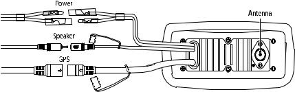
After the cord is connected to power, slide the bullet connectors on the Power Cord into their mates (with the same coloured wire) on the rear of the radio. (See Figure 2-3 .)
The Ray54E is designed to be operated on a 12 volt (nominal) system. If battery voltage drops below 10.5 VDC (approximately), the  icon appears on the LCD (see page 15). Discontinue using the radio if a low voltage condition occurs as performance would be unreliable. If voltage exceeds 16 VDC, the message EXCESSIVE VOLTAGE appears on the dot matrix display and an alarm is sounded. Immediately disconnect the radio if a high voltage condition occurs as the unit could become damaged.
Figure 2-3: Wiring Connections

Chapter 2: Installation |
7 |
|
|
2.4 External Speaker Connections
Located just below the power cord is a cable for connection to an optional external speaker. Connect the white(+) wire and black (–) wire to the speaker observing polarity as it is marked on the speaker. Mate the connector with its counterpart on the rear of the radio. (See Figure 2-3 .) If not connecting an external speaker, please leave the dust cover on the cable connector.
2.5 Grounding
While special grounding is not generally required for VHF radiotelephone installations, it is good marine practice to properly ground all electronic equipment to the boat’s earth ground system. The Ray54E can be connected to ground by installing the supplied screw and lock washer in the threaded hole labelled GND on the main unit’s rear panel just below the antenna jack. Then attach a wire from this screw to the nearest ship’s earth ground connection point. The recommended wire to be used for such grounding is #10 AWG.
2.6 GPS/NMEA Data
The Ray54E accepts NMEA 0183 (V1.5) data from a position determining device (GPS) to provide the Latitude and Longitude position information that is transmitted during a DSC Distress Call. When a valid NMEA signal is detected, the GPS indicator appears on the LCD. When no valid NMEA signal is detected, the NO GPS indicator appears.
Connect the NMEA OUT + and NMEA OUT– signals from the positioning device to the GPS + (yellow) and GPS – (green) wires, respectively, of the GPS cable. Mate the connector with its counterpart on the rear of the radio, aligning the arrows on the two connectors. (See Figure 2-3 .) If not connecting a GPS, please leave the dust cover on the cable connector.
An example of how to make the connections using a suitable connector block is shown in the following drawing. For specific instructions how to connect your particular GPS, please refer to the handbook that came with that device.
Figure 2-4: GPS Wiring
8 |
Ray54E VHF Radio |
|
|
2.7 Antenna Connections
The coaxial VHF antenna cable connects to the Ray54E antenna jack on the rear panel using a PL259 VHF type connector. The antenna cable length can be critical to performance. If you are uncertain, contact a professional installer or call Raymarine Product Support. If a longer cable length is required, RG-8x (50 ohm) marine coaxial cable or equivalent cable can be used for runs up to a maximum of 50 feet. If the distance required is even greater, Raymarine recommends using low loss RG-213 or equivalent cable for the entire run to avoid excessive losses in power output.
If the antenna RF connector is likely to be exposed to the marine environment, a protective coating of grease (Dow Corning DC-4 or similar) can be applied to the connector before connecting it to the radio. Any other extensions or adapters in the cable run should also be protected by silicon grease and then wrapped with a waterproofing tape.
Antenna Mounting Suggestions
Mounting the VHF antenna properly is very important because it will directly affect the performance of your VHF radio. Use a VHF antenna designed for marine vessels.
Since VHF transmission is essentially line-of-sight, mount the antenna at a location on the vessel that is free of obstruction to obtain maximum range.
If you must extend the length of the coaxial cable between the antenna and the radio, use a coaxial cable designed for the least amount of power loss over the entire cable length.
Antenna Mounting and EME Exposure
For optimal radio performance and minimal human exposure to radio frequency electromagnetic energy, make sure the antenna is:
•connected to the radio before transmitting
•properly mounted
•located where it will be away from people
•located at least 1.5 metres (5 feet) from the radio

Chapter 3: Getting Started |
9 |
|
|
Chapter 3: Getting Started
3.1 Keypad and Rotary Knobs
Several of the keys on the front panel of the main unit serve multiple purposes. For the most part, the function indicated on the first line of the key is accessed by pressing and releasing that key. The function indicated on the second line of the key is accessed by pressing and holding the key for three seconds.
Figure 3-1: Ray54E Keys Layout

10 Ray54E VHF Radio
Microphone Keys
Key Name |
Press & Release (<3 sec.) |
Press & Hold (>3 sec.) |
|
|
|
1. PTT |
Push-to-Talk |
Push-to-Talk |
|
|
|
2. UP/DOWN |
Channel increment/decrement and |
Rapid channel change and navigating |
|
navigating menu item selections |
menu item selections |
|
|
|
3. 16/PLUS |
Switch between the Priority and |
Switches to Secondary Priority (PLUS) |
|
Working Channels |
channel; If already tuned to the PLUS |
|
|
channel, programs a new PLUS chan- |
|
|
nel. |
4. HI/LO |
TX Power High/Low and ACCEPT key |
|
for menu item selections |
TX Power High/Low and ACCEPT key for menu item selections
Main Unit Rotary Keys
Key Name |
Function |
|
|
5. CH/PUSH |
Rotate to increment/decrement channels or navigate menu item |
|
selections |
|
|
6. PWR/VOL |
Power radio ON / OFF and adjust volume level |
|
|
7. SQ |
Adjust squelch threshold level |
|
|
Main Unit Push Keys
Key Name |
Press & Release (<3 sec.) |
Press & Hold (>3 sec.) |
|
|
|
5. CH/PUSH |
ACCEPT menu item selections |
ACCEPT menu item selections |
|
|
|
8. DW/TRI |
Dual Watch Mode |
Tri Watch Mode |
|
|
|
9. CALL/MENU |
Activate DSC functions |
Activate Menu functions |
|
|
|
10. HL/USER |
TX Power High/Low |
USER (Saved Memory Channel) Mode |
|
|
|
11. SCAN/SAVE |
Scan ON/OFF |
SAVE/DELETE channel to/from memory |
|
|
|
12.16/PLUS |
Switch between the Priority |
Switches to Secondary Priority (PLUS) |
|
and Working Channels |
channel; If already tuned to the PLUS chan- |
|
|
nel, programs a new PLUS channel. |
|
|
|
13.CLEAR |
Cancel function |
Weather Channel Mode, if so programmed |
|
|
|
14. DISTRESS |
Designate Distress Type |
Make Distress Call |
|
|
|
Chapter 3: Getting Started |
11 |
|
|
Microphone
1. PTT
Press this Push-to-Talk key to transmit.
2. UP/DOWN
Use the arrow keys to change the active channel number. Press and hold for rapid channel changing. You can also use these keys to scroll through DSC Call and Menu Mode options and make item selections.
3. 16/PLUS
Use this key to switch to the priority channel or to change the value of the Secondary Priority (PLUS) Channel.
4. HILO
Use this key to toggle the transmit power from HIGH to LOW. You can also use it to accept DSC Call and Menu Mode selections.
Main Unit
5. CH
Rotate this knob to change the current channel number and to change values in Menu mode or during programming. Press the knob to enter values selected in Menu mode or during programming.
6. PWR/VOL
Use this knob to turn the radio ON and OFF and to set the volume.
7. SQ

 Use this knob to set the squelch threshold, which cuts off the receiver when the signal is too weak for reception of anything but noise.
8. DW/TRI
Press and release this key to select Dual Watch mode, which monitors the current working channel and CH 16 in cycle. Press and hold to select Tri Watch, which monitors CH 16, the current working channel and the channel you have set as the Secondary Priority (PLUS) Channel in cycle. See Section 4.12.

12 |
Ray54E VHF Radio |
|
|
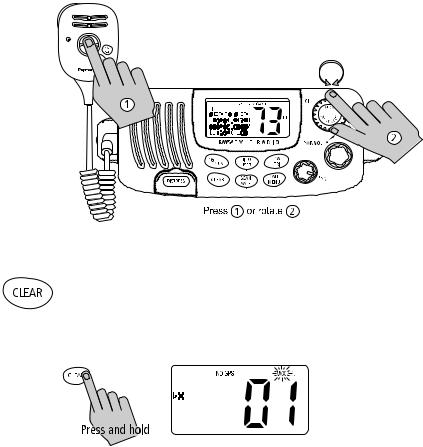
9. CALL/MENU
Press and release this key to select to enter DSC Call Mode, which is used for making DSC Calls and viewing the DSC Call Logs and the DSC Call Phonebook.
A Maritime Mobile Service Identity (MMSI) number is required to operate the DSC equipment in this radio. This number directs DSC calls directly to your radio, much like a telephone number. You can program the MMSI number yourself one time only using the Menu Operation described in Section 6.8, DSC Setup. Otherwise, your Raymarine dealer can program or change the number for you.
If the MMSI number has not yet programmed, the message DSC IS NOT OPERATIONAL...PLEASE ENTER MMSI ID is displayed in the dot matrix display when you press and release CALL/MENU.
DSC Call menu structure is outlined in the following drawing. Full details on DSC call operation are described in Chapter 5:

Chapter 3: Getting Started |
13 |
|
|
Press and hold CALL/MENU to select Menu Mode, which is used to set up the radio. The menu structure is outlined in the following drawing. Menu operations are fully described in Chapter 6:
10. HILO/USER
Press and release this key to toggle the transmit power from HIGH to LOW. Press and hold to select User Channel Mode, which displays only the channels that you have saved to memory. User Mode is described in Section 4.13.
11. SCAN / SAVE
Press and release this key to enter one of the Scan Modes, which are described in Section 4.10. Press and hold to enter a channel into the radio’s memory. This function is described in Section 4.11.
14 |
Ray54E VHF Radio |
|
|
12. 16/PLUS
Use this key to switch to the priority channel or to change the value of the Secondary Priority (PLUS) Channel.
13. CLEAR
Press and release to terminate a function and return to the last-used channel. Press and hold to select the Weather mode (if available).
14. DISTRESS
Push down the spring-loaded cover and press this key to make a DSC Distress Call. Instructions for making a Distress Call are described in Section 5.5.
3.2 LCD Display
The following describes the functional characters on the Ray54E’s LCD.
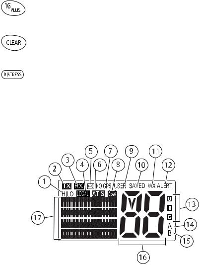
Figure 3-2: Ray54E LCD Layout
1. (HI/LO) TX Power
Indicates whether transmit power is set for 25 watts (HI) or 1 watt (LO).
2. (TX) Transmitting
Indicates the PTT is being pressed and the radio is transmitting.
Chapter 3: Getting Started |
15 |
|
|
3. (RX) Receiving
Indicates that the radio is receiving a radio signal.
4. (LOCAL) Local/Distant Mode
Indicates the radio is in Local Reception mode, which decreases receiver sensitivity in high traffic areas to decrease unwanted reception. Only available in Ray54 (North American) model.
5.  DSC Message
Indicates the radio has received a DSC Call. Details of the call can be viewed in the DSC log. See Section 5.8.
6. ATIS Active
Indicates ATIS transmission is enabled.
7. NO GPS
When GPS appears, positional data is available. When NO GPS appears, the radio is not receiving positional data.
8.  Battery Low
Indicates vessel battery voltage is below 10.5 VDC, which is the lowest voltage at which the radio can be reliably operated.
9. (USER) Favourite Channel Mode
Indicates the radio is in User Mode. User Mode displays only the channels that you have saved to memory, enabling you to easily scan your favourite channels while bypassing unwanted or seldom-used channels.
10. (SAVED) Memory Mode
Indicates the current channel has been saved in memory. Appears during Saved Scan mode. Only saved channels are scanned during USER mode.
11. (WX) Weather Channel
Weather channel mode is active. US and Canada only.
12. (ALERT) Weather Alert
Monitoring for weather alert broadcasts. US and Canada only.

16 |
Ray54E VHF Radio |
|
|
13. (U I C) Channel Set
Indicates which channel set is selected: US, International or Canadian.
Note: Special licensing is required to receive the US and Canadian channel sets.
14. (A) Simplex Channel
Indicates that the currently-selected channel is simplex; you transmit and receive on the same frequency. Used with US and Canadian channels only.
15. (B) Receive-only Channel
Indicates that you cannot transmit on the currently-selected channel; it is receive-only. Used with Canadian channels only.
16. Channel Number
Displays the current channel number.
17. Dot Matrix Display
Indicates radio functions or special conditions. The type of information displayed depends on the situation. Figure 3-3 demonstrates a typical screen in normal operating mode. The screen is different when sending/receiving a DSC Call (see Chapter 5:) or setting up a Menu item (see Chapter 6:).
Note: In the following sample:
(1)The Channel Name is editable (see page 70).
(2)Valid position data received from a GPS or manually entered (see page 64).
(3)Last line may contain COG/SOG data instead of time (see page 68).
Figure 3-3: Typical Dot Matrix Display Data

Chapter 4: General Operations |
17 |
|
|
Chapter 4: General Operations
4.1 Turning the Power ON and OFF
Turn the PWR/VOL knob clockwise until it clicks.
When the unit powers up in Normal mode it:
1.Beeps, illuminates the backlight at full brightness, and displays all segments and indicators for 2 seconds.
2.Displays the software version number on the dot matrix display.
3.Recalls the last CH number, TX power settings and operation mode. If no last-used setting data exists, goes to CH 16 and high TX Power.
When GPS Data is available, extended position data is also displayed with the offset time on the dot matrix display. This information will be displayed when display option for the position and time is enabled on the Menu. See
Section 6.5.
To turn the unit OFF, rotate the Volume knob completely counter clockwise until it clicks.
4.2 Setting the Volume
Adjust the PWR/VOL knob to control the loudspeaker volume level. Turn clockwise to increase the volume; counter clockwise to decrease the volume.
Note: Key press beep volume is also controlled by the VOL level.
4.3 Setting the Squelch
The Squelch circuit sets the threshold for cutting off the receiver when the signal is too weak for reception of anything but noise.
To properly set the squelch, rotate the SQ knob counter clockwise until audio is heard. Then rotate clockwise until background noise disappears.
4.4 Setting the Power Output
The choice of power output is dependent upon the distance of transmission and transmitting conditions. International Regulations state you must use the minimum power possible for satisfactory communication.

18 |
Ray54E VHF Radio |
|
|
Press and release the HL/USER key on the main unit or microphone to toggle the TX power from LOW (1 watt) to HIGH (25 watts). The corresponding LO or HI indicator appears on the LCD.
As a part of marine communications courtesy, initial contact should always be attempted using low power. You should switch to high power only when contact can not be made on low power in emergency situations.
Note: Some channels are limited by regulation to be low power only. If the HILO operation request is denied, an error tone beeps.
4.5 Setting the Channel
On the microphone...
Press and release the UP arrow to increment the channel number. Press and release the DOWN arrow to decrement the channel. Press and hold either key for rapid channel scrolling.
On the main unit...
Rotate the CH knob clockwise to increment the channel number.
Rotate the CH knob counter clockwise to decrement the channel number.
Chapter 4: General Operations |
19 |
|||||||||
|
|
|
|
|
|
|
|
|
|
|
|
|
|
|
|
|
|
|
|
|
|
|
|
|
|
|
|
|
|
|
|
|
|
|
|
|
|
|
|
|
|
|
|
|
|
|
|
|
|
|
|
|
|
|
4.6 Selecting a Weather Channel (If Available)
The US National Oceanic and Atmospheric Administration (NOAA) broadcasts continuous weather reports and severe weather alerts, as needed. If so equipped, your Ray54E is programmed to receive 10 weather channels and sound an alarm if a weather alert is received.
Press and hold the CLEAR key to enter Weather mode.
The WX indicator appears on the LCD. Rotate the CH knob to select from channels WX01 through WX10.
Press and release the CLEAR key again to return to normal operation.
Note:
1.WX broadcasts can only be heard in the US and Canada.
2.The Ray54E can receive these broadcasts only if the unit has been upgraded by the distributor to use WX Channels.
3.During Weather mode, the PTT, HILO/USER, SCAN/SAVE and DW/TRI keys are disabled and an error beep sounds if pressed.

20 |
Ray54E VHF Radio |
|
|
Weather Alert Operation (If Available)
Weather Alert is toggled ON and OFF by pressing and holding CLEAR key in the weather mode. The ALERT indicator illuminates.
When Weather Alert function is enabled and the radio is tuned to the normal working channel, the last-used weather channel is checked every four minutes for weather alert tone. If the alert tone is detected, the WX and ALERT indicators flash and an alarm sounds.
The radio automatically turns to the currently-monitored WX channel where the weather alert has been detected. The alert is detected in all modes of operation (Standby, Dual and Tri Watch, Scan, etc.)
Note: The Ray54E can receive weather alert broadcasts in the US or Canada only if the unit has been programmed by the distributor to use WX Channels.
4.7Selecting the Priority Channel
The Ray54E provides you with a dedicated key for switching to the Priority Channel 16.
If not already tuned to the Priority Channel 16, press and release the 16/ PLUS key to switch to CH16 at high power.
PRIORITY CH appears in the dot matrix display.
If already on CH 16, press and release the 16/PLUS to return to the last-used working channel.
Note: When the priority channel is selected, it is always set to HIGH transmit power. You may reduce power if desired by pressing the HI/LO key.
The 16/PLUS key also can be used to cancel all modes and switch to CH 16.
Loading...