


Raystar 125
1
Drill
6mm (
1
/4 in)
Drill bit
20mm (
13
/16 in)
Drill bit
Phillips
screwdriver
Adhesive tape
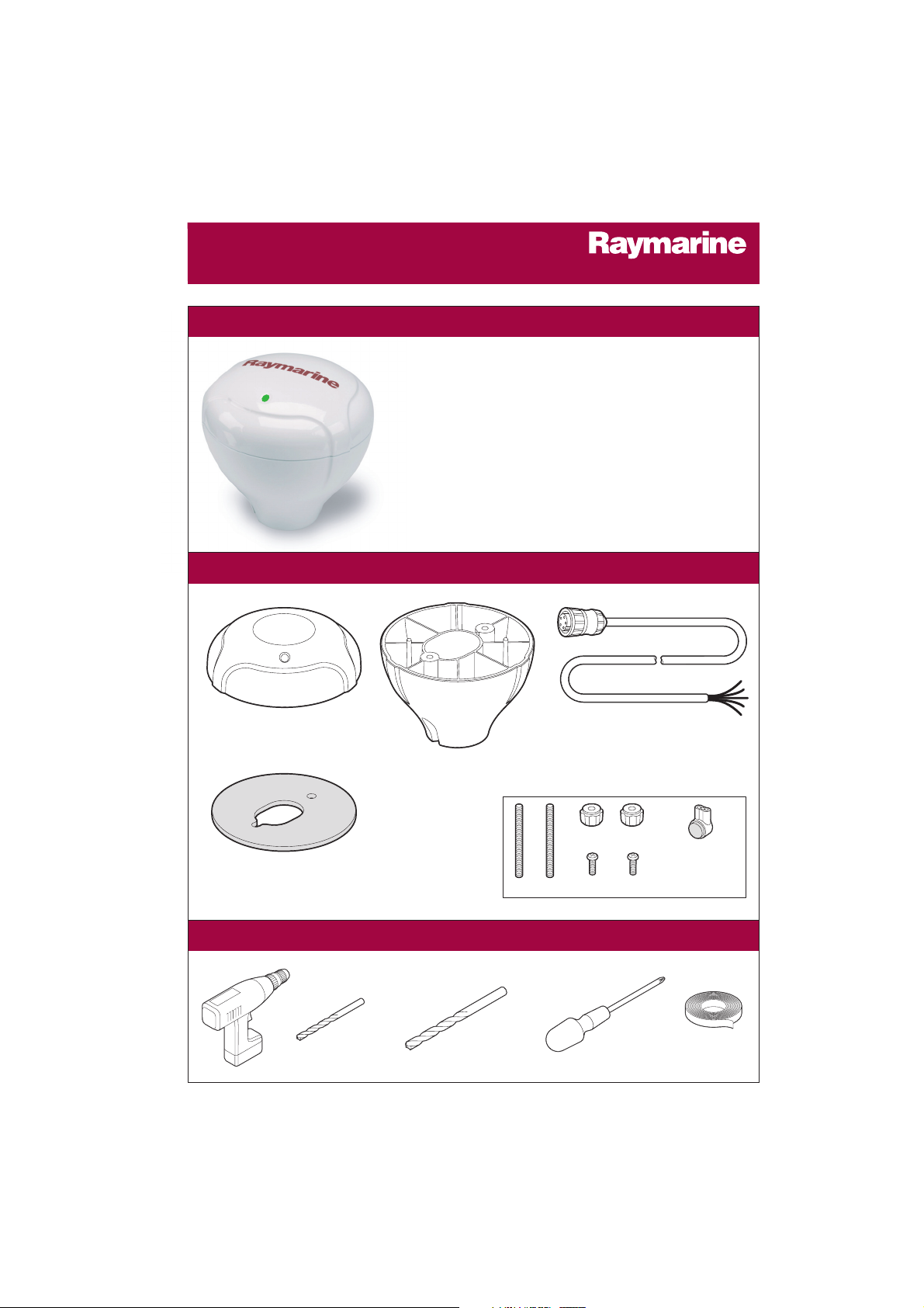
What tools do I need to install it?....
Part No: R38103
Raystar RS125 GPS Receiver
Part No: E35018
Pole mount kit
Studs (x2)
Thumb nuts (x2)
Part No: R38104
10m (33ft) NMEA/SeaTalk
connection cable
Flush mount gasket
Screws (x2)
The Raystar RS125 GPS Receiver has no user serviceable parts.
D7471_2
3- way
Scotchlok
connectors (x5)
TM
Your handbook contains an explanation of how to install,
operate and maintain your Raystar RS125 GPS Receiver.
Intended Use
This product is a GPS antenna with a built-in position
fixing receiver using either NMEA0183 (Version 2.3 or
later), or Raymarine SeaTalk data output. The intended
application is for leisure marine boats and workboats not
covered by IMO/SOLAS carriage requirements.
Raystar 125 GPS Receiver
Owner's Handbook
www.raymarine.com
Welcome to the Raystar RS125 GPS Receiver
What's in the box?....
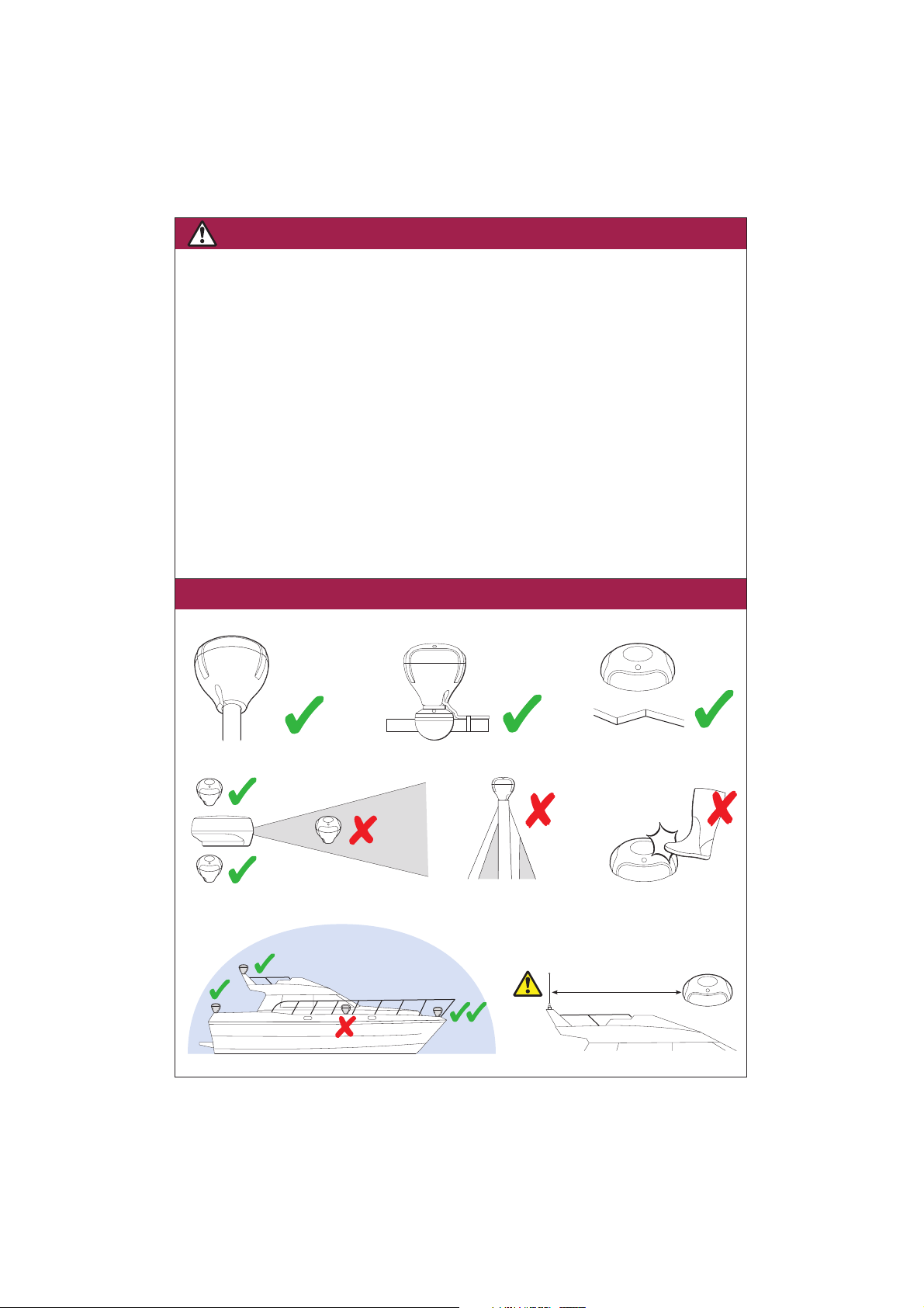
2 RS125 GPS Receiver
Top of
the mast
No trip
or tread
Pole
mount
Flush
mount
Rail
mount
Above the beam
Below the beam
In the
beam
Radar
Clear view of the sky
Minimum 1.0 m (3 ft)
VHF Radio and other antenna
D7472_2
WARNING: Navigation aid
Although this product has been designed to be accurate and reliable, many factors
can affect its performance. As a result, it should only be used as an aid to navigation
and should never replace common sense and navigational judgement. Always
maintain a permanent watch so you can respond to situations as they develop.
WARNING: Product installation
This equipment must be installed and operated in accordance with the instructions
contained in this handbook. Failure to do so could result in poor product
performance, personal injury and/or damage to your boat.
WARNING: Electrical safety
Make sure the power supply is switched off before you make any electrical
connections.
WARNING: Lithium battery
This unit has a lithium battery fitted. DO NOT attempt to recharge this battery. DO
NOT incinerate this battery. Ensure you follow local regulations when disposing of
this unit.
Safety notices
Where can I install the unit?....
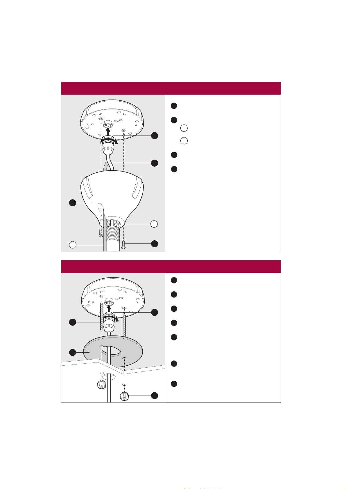
3
Use the template supplied in this handbook to
mark the two fixing holes and the center hole.
Drill the holes using the drill sizes shown on
the template.
Screw the two fixing studs into the underside
of the receiver unit.
Place the waterproof gasket into position on
the underside of the receiver.
Attach the connector securely to the plug in
the base of the unit and pass the cable
through the center hole on the mounting
surface.
Carefully position the receiver so that the
mounting studs pass through the holes in the
mounting surface.
Secure the receiver to the mounting surface
using the two thumb nuts (these should be
hand-tight only).
1
2
3
4
5
6
7
5
3
7
4
b
1
3
2
4
a
Securely attach the pole mount base to a
suitable pole.
Pass the cable and connector through either
the center of the pole mount bracket and
the pole, or
the cable exit hole alongside the center
hole.
Attach the connector securely to the plug in
the base of the unit.
Secure the receiver to the pole mount base
using the screws provided.
1
2
3
4
a
b
To mount the unit on a pole....
To flush mount the unit....
D7473_2
Notes:
1. To mount the receiver on a pole, you will need
a pole of suitable length with a 1 inch 14 TPI
thread not exceeding 20mm in length.
2. To rail mount the receiver you will need to
purchase a suitable rail mount bracket
 Loading...