


 Loading...
Distributed by
Any reference to Raytheon or RTN in this manual should be interpreted as Raymarine. The names Raytheon and RTN are owned by the
Raytheon Company.

ST6001+
Autopilot
Control Unit
Owner’s
Handbook
Document number: 81190-2
Date: May 2001
ii |
ST6001+ Autopilot Control Unit - Owner’s Handbook |
Autohelm, HSB (High Speed Bus), SailPilot, SeaTalk and SportPilot are registered trademarks of Raymarine Ltd.
Raymarine, AST (Advanced Steering Technology), AutoAdapt, AutoLearn, AutoRelease, AutoSeastate, AutoTack, AutoTrim, FastTrim, GyroPlus, RayGyro, RayPilot and WindTrim are trademarks of Raymarine Ltd.
Handbook contents © Raymarine Ltd 2001.

Preface |
iii |
Contents |
|
About this handbook ......................................................... |
vii |
Important Information ..................................................... |
viii |
Warranty ................................................................................... |
viii |
Safety notices ........................................................................... |
viii |
EMC conformance ..................................................................... |
ix |
Handbook information ............................................................... |
ix |
Chapter 1: Introduction ............................................................ |
1 |
Chapter 2: Basic Operation ....................................................... |
3 |
2.1 Using the control unit ................................................................ |
4 |
Start-up mode ............................................................................ |
4 |
Keypad functions ...................................................................... |
4 |
Display layout ........................................................................... |
5 |
2.2 Using Auto mode ...................................................................... |
6 |
Engaging the autopilot (Auto mode) ......................................... |
6 |
Disengaging the autopilot (Standby mode) .............................. |
6 |
Changing course in Auto mode ................................................. |
7 |
Adjusting performance – Type 150G/400G ............................. |
7 |
Adjusting performance – Types 150/400 and 100/300 ............. |
8 |
Off Course warning ................................................................. |
10 |
Dodging obstacles and then resuming course ......................... |
10 |
Using sail boat features ........................................................... |
12 |
2.3 Adjusting display/keypad lighting ......................................... |
14 |
Chapter 3: Advanced Operation ............................................ |
15 |
3.1 Using Track mode ................................................................... |
16 |
Selecting Track mode ............................................................. |
16 |
Exiting Track mode ................................................................. |
17 |
Cross track error ...................................................................... |
17 |
Tidal stream compensation ..................................................... |
18 |
Waypoint arrival and advance ................................................. |
19 |
Waypoint Advance warning – summary ................................. |
20 |
Dodges in Track mode ............................................................ |
21 |
Safety in Track mode .............................................................. |
22 |
3.2 Using Wind Vane mode – sail boats ........................................ |
23 |
About Wind Vane mode .......................................................... |
23 |
Selecting Wind Vane mode ..................................................... |
24 |
Exiting Wind Vane mode ........................................................ |
24 |
Adjusting the locked wind angle ............................................. |
24 |

iv |
ST6001+ Autopilot Control Unit - Owner’s Handbook |
|
|
Returning to the previous wind angle (LAST WND) ............. |
25 |
|
Dodges in Wind Vane mode .................................................... |
25 |
|
Wind Shift warning ................................................................. |
26 |
|
Using AutoTack in Wind Vane mode ...................................... |
26 |
|
Operating hints for Wind Vane mode ...................................... |
27 |
3.3 |
Adjusting the rudder gain ........................................................ |
27 |
3.4 |
Displaying data pages ............................................................. |
29 |
|
Watch timer ............................................................................. |
30 |
|
Warning messages .................................................................. |
31 |
Chapter 4: Fault Finding & Maintenance .............................. |
33 |
|
4.1 |
Fault finding ............................................................................ |
34 |
|
Common autopilot problems .................................................. |
34 |
|
Autopilot alarm messages ....................................................... |
35 |
4.2 |
General maintenance .............................................................. |
37 |
|
Routine checks ........................................................................ |
37 |
|
Cleaning the display ................................................................ |
37 |
|
EMC advice ............................................................................ |
37 |
4.3 |
Product support ....................................................................... |
38 |
Chapter 5: Installing the ST6001+ .......................................... |
43 |
|
5.1 |
Select the location ................................................................... |
44 |
|
Site requirements .................................................................... |
44 |
5.2 |
Control unit installation .......................................................... |
47 |
|
Surface mount control units .................................................... |
47 |
|
Flush mount control units ....................................................... |
48 |
5.3 |
SeaTalk connections ............................................................... |
49 |
5.4 |
NMEA connections ................................................................ |
50 |
|
Receiving NMEA data ............................................................ |
50 |
5.5 |
Functional test – repeater units only ....................................... |
53 |
Chapter 6: Commissioning the Autopilot ............................ |
55 |
|
6.1 |
Dockside Checks .................................................................... |
56 |
|
Step 1 - Switch on ................................................................... |
56 |
|
Step 2 - Check the SeaTalk and NMEA connections .............. |
57 |
|
Step 3 - Check the autopilot operating sense ........................... |
58 |
|
Step 4 - Adjust basic autopilot settings ................................... |
59 |
6.2 |
Seatrial Calibration ................................................................. |
63 |
|
Calibrating the compass .......................................................... |
64 |
|
Adjusting autopilot settings .................................................... |
68 |

Preface |
v |
Chapter 7: Adjusting Autopilot Settings .............................. |
75 |
7.1 Calibration basics .................................................................... |
76 |
Calibration groups .................................................................. |
76 |
Accessing the Calibration mode ............................................. |
78 |
7.2 Display Calibration ................................................................ |
79 |
Display Calibration screens .................................................... |
79 |
7.3 User Calibration ...................................................................... |
83 |
User Calibration screens ......................................................... |
83 |
7.4 Seatrial Calibration ................................................................. |
87 |
7.5 Dealer Calibration ................................................................... |
88 |
Accessing Dealer Calibration ................................................. |
88 |
Dealer Calibration screens and settings .................................. |
88 |
Dealer Calibration defaults: Types 150/150G & 400/400G ... |
97 |
Dealer Calibration options: Types 150/150G & 400/400G .... |
98 |
Appendix: Using the ST6001+ |
|
With Non-150/400 Autopilots ............................................. |
99 |
Using the autopilot (non-150/400 systems) ............................ |
100 |
Commissioning the autopilot (non-150/400 systems) ............ |
101 |
Dockside Checks .................................................................. |
101 |
Seatrial Calibration ............................................................... |
101 |
Calibration mode (non-150/400 systems) ............................... |
102 |
Calibration groups ................................................................ |
102 |
Dealer Calibration screens .................................................... |
104 |
Dealer Calibration: possible settings with Type 100/300 ..... |
110 |
Specifications ..................................................................... |
111 |
ST6001+ control unit .............................................................. |
111 |
Course computer functions ..................................................... |
111 |
Glossary .............................................................................. |
112 |
Index .................................................................................... |
115 |
vi |
ST6001+ Autopilot Control Unit - Owner’s Handbook |
Preface |
vii |
About this handbook
Welcome to the handbook for the ST6001+ autopilot control unit. This handbook contains two main parts:
Part 1: Using the ST6001+
1 |
Chapter 1: Introduction |
page 1 |
|
Introduces the autopilot, its features and its use. |
|||
|
|
||
|
|
|
|
|
|
|
|
|
Chapter 2: Basic Operation |
|
|
2 |
Covers basic autopilot operation: using Auto mode, |
page 3 |
|
adjusting autopilot performance, and changing the control |
|||
|
|
||
|
unit lighting. |
|
|
|
|
|
|
|
|
|
|
3 |
Chapter 3: Advanced Operation |
|
|
Explains how to use Track and Wind Vane modes, adjust |
page 15 |
||
|
rudder gain and display data pages. |
|
|
|
|
|
|
|
|
|
|
4 |
Chapter 4: Fault Finding & Maintenance |
|
|
Provides general maintenance procedures and |
page 33 |
||
|
trouble-shooting information (including alarm messages). |
|
|
|
|
|
|
Part 2: Installing the ST6001+ |
|
||
|
|
|
|
5 |
Chapter 5: Installing the ST6001+ |
|
|
Explains how to install your ST6001+ control unit and |
page 43 |
||
|
connect it to your autopilot system. |
|
|
|
|
|
|
|
|
|
|
6 |
Chapter 6: Commissioning the Autopilot |
|
|
Covers dockside checks after installation, and the initial |
page 55 |
||
|
seatrial calibration. |
|
|
|
|
|
|
|
|
|
|
7 |
Chapter 7: Adjusting Autopilot Settings |
|
|
Provides details on adjusting the control unit and autopilot |
page 75 |
||
|
settings in Calibration mode. |
|
|
|
|
|
|
At the end of this handbook we have included an appendix, product specifications, a glossary, an index, installation templates, and warranty information.
Note: This handbook contains important information about installing, using and maintaining your new Raymarine product. To get the best from the product, please read this handbook thoroughly.
viii |
ST6001+ Autopilot Control Unit - Owner’s Handbook |
Important Information
Warranty
To register your new Raymarine product, please take a few minutes to fill out the warranty card. It is important that you complete the owner information and return the card to us to receive full warranty benefits.
Safety notices
WARNING: Product installation
This equipment must be installed and operated in accordance with the instructions contained in this handbook. Failure to do so could result in poor product performance, personal injury and/or damage to your boat.
WARNING: Electrical safety
Make sure the power supply is switched off before you make any electrical connections.
WARNING: Calibration
We supply this product calibrated to default settings that should provide initial stable performance for most boats. To ensure optimum performance on your boat, you must complete Chapter 6: Commissioning the Autopilot before use.
WARNING: Navigation aid
Although we have designed this product to be accurate and reliable, many factors can affect its performance. As a result, it should only be used as an aid to navigation and should never replace common sense and navigational judgement. Always maintain a permanent watch so you can respond to situations as they develop.
Your Raymarine autopilot will add a new dimension to your boating enjoyment. However, it is the skipper’s responsibility to ensure the safety of the boat at all times by following these basic rules:
•Ensure that someone is present at the helm AT ALL TIMES, to take manual control in an emergency.
Preface |
ix |
•Make sure that all members of crew know how to disengage the autopilot.
•Regularly check for other boats and any obstacles to navigation – no matter how clear the sea may appear, a dangerous situation can develop rapidly.
•Maintain an accurate record of the boat’s position by using either a navigation aid or visual bearings.
•Maintain a continuous plot of your boat’s position on a current chart. Ensure that the locked autopilot heading will steer the boat clear of all obstacles. Make proper allowance for tidal set – the autopilot cannot.
•Even when your autopilot is locked onto the desired track using a navigation aid, always maintain a log and make regular positional plots. Navigation signals can produce significant errors under some circumstances and the autopilot will not be able to detect these errors.
EMC conformance
All Raymarine equipment and accessories are designed to the best industry standards for use in the recreational marine environment. The design and manufacture of Raymarine equipment and accessories conform to the appropriate Electromagnetic Compatibility (EMC) standards, but correct installation is required to ensure that performance is not compromised.
Handbook information
To the best of our knowledge, the information in this handbook was correct when it went to press. However, Raymarine cannot accept liability for any inaccuracies or omissions it may contain. In addition, our policy of continuous product improvement may change specifications without notice. As a result, Raymarine cannot accept liability for any differences between the product and the handbook.
x |
ST6001+ Autopilot Control Unit - Owner’s Handbook |

Part 1:
Using the
ST6001+
ST6001+ the Using 1: Part

Part 1: Using the ST6001+
Chapter 1: Introduction |
1 |
Chapter 1: Introduction
Introduction 1
-1 D5460
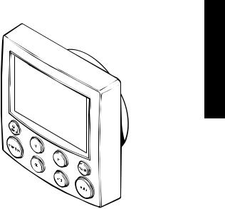
The Raymarine ST6001 Plus (ST6001+) is a SeaTalk® compatible autopilot control unit. It is designed as the main control unit for Raymarine Type 150, 150G, 400 and 400G course computers.
The ST6001+ control unit has the following modes:
1.Standby: autopilot off (see page 6)
2.Auto: autopilot steers the boat to maintain a locked heading (see page 6)
3.Track: autopilot steers the boat to maintain a track between two waypoints created on a navigation aid (see page 16)
4.Wind Vane: autopilot steers the boat to maintain a course relative to a true or apparent wind angle (see page 23)
5.Calibration: so you can adjust the autopilot to give optimum performance for your boat (see page 76). This includes automatic compass deviation correction (all autopilots) and AutoLearn automatic steering calibration (Type 150G/400G systems only)
The ST6001+ also provides:
•automatic tack (AutoTack) in Auto and Wind Vane modes
•Northerly/Southerly heading compensation
•waypoint advance feature in Track mode

1 Introduction
2 |
ST6001+ Autopilot Control Unit - Owner’s Handbook |
Functions with Type 150/150G and 400/400G autopilots
The functions provided with Type 150/150G and Type 400/4000G autopilots depend on whether the course computer contains an internal GyroPlus yaw sensor:
Type 150G/400G (with GyroPlus) |
Type 150/400 (without GyroPlus) |
|
|
Internal GyroPlus yaw sensor provides |
Full basic functionality: uses Raymarine |
enhanced course keeping using AST |
steering algorithm without AST |
(Advanced Steering Technology) |
|
|
|
Improved track-keeping |
Improved track-keeping |
|
|
Steering to true and apparent wind in |
Steering to true and apparent wind in |
Wind Vane mode |
Wind Vane mode |
|
|
Improved calibration access, including |
Improved calibration access, but |
AutoLearn (self-learning calibration) |
without AutoLearn |
|
|
Extended systems
You can connect the ST6001+ to other Raymarine SeaTalk equipment so it can send and receive SeaTalk data:
•it can use wind information from a SeaTalk wind instrument for Wind Vane steering
•it can use waypoint information from a SeaTalk navigation instrument to provide track control
•it can use boat speed from a SeaTalk speed instrument to optimize track-keeping performance
You can also use the ST6001+ autopilot with any navigator (GPS, Decca, Loran) or wind instrument that transmits National Marine Electronics Association (NMEA) 0183 data.
The ST6001+ can display SeaTalk and NMEA instrument data in a user-defined selection of data pages. When you are using the ST6001+ to repeat instrument data, it shows a ‘pop-up’ pilot page for 5 seconds whenever you make a change in autopilot control.
Compatibility with other autopilots
The ST6001+ is also compatible with Raymarine Type 100 and Type 300 course computers (see the Appendix for more details). You can also use it as an additional repeater control unit for any SeaTalk autopilot system, allowing autopilot control from a secondary location.

Chapter 2: Basic Operation |
3 |
Chapter 2: Basic Operation
The sections in this chapter explain how to use the basic functions on your ST6001+ autopilot control unit:
2.1 |
Using the control unit |
|
|
Summarizes the key functions and screen layout on the |
page 4 |
||
|
ST6001+ control unit. |
|
|
|
|
|
|
|
|
|
|
|
Using Auto mode |
|
|
2.2 |
Provides instructions for engaging/disengaging the |
page 6 |
|
autopilot, using Auto mode and adjusting the |
|||
|
|
||
|
autopilot’s performance. |
|
|
|
|
|
|
|
|
|
|
2.3 |
Adjusting display/keypad lighting |
|
|
Explains how to change the lighting on the control unit |
page 14 |
||
|
display and keypad. |
|
|
|
|
|
Note: If you are using the control unit with a non-150/400 autopilot system, refer to the notes in the Appendix.
Operation Basic 2

2 Basic Operation
4 |
ST6001+ Autopilot Control Unit - Owner’s Handbook |
2.1 Using the control unit
Start-up mode
The autopilot always powers up in Standby mode with the display showing the boat’s current compass heading.
Note: You can press standby at any time to return to manual steering.
Keypad functions
The autopilot is controlled using simple push-button operations, all of which are confirmed with a short beep. In addition to the main single-key functions, there are several dual key operations.
-1 plus -10
Press together for AutoTack to port
DISP
Press to display data pages
Press for 1 second for lamp control
STANDBY
Press for Standby mode
Press for 2 seconds
to enter Calibration mode
-1 plus +1
Press for Response level Press for 1 second for Rudder Gain
Course change keys
Port 1˚ Starboard 1˚
Port 10˚ Starboard 10˚
STANDBY plus AUTO
Press for Wind Vane mode (if a wind vane is connected)
Press for 1 second for Last Wind Press again to accept Last Wind
+1 plus +10
Press together for AutoTack to starboard
TRACK
Press for Track mode from Auto (if a navigator is connected)
Press to accept waypoint advance
Press for 1 second to skip waypoint
AUTO
Press for Auto mode
Press for 1 second for Last Heading
Press again to accept Last Heading
D5449-1

Chapter 2: Basic Operation |
5 |
Display layout
The ST6001+ display screen provides the following information:
Variable text region (up to 9 characters/digits)
Heading indicators
Distance units:
• no units = kilometres
• nm = nautical miles
• SM = statute miles
Autopilot mode indicators
Port and Starboard direction-to-steer indicators
Calibration mode indicator (displayed on calibration pages)
Rudder position indicator or error bar
D5457-1
The bar graph at the bottom of the screen is normally a rudder position indicator. This indicates the current position of the rudder, as measured by the rudder position sensor.
Note: You can change this to a heading/cross track/wind error bar in Display Calibration, see page 79.
Operation Basic 2
6 |
ST6001+ Autopilot Control Unit - Owner’s Handbook |
2.2 Using Auto mode
CAUTION:
Before using Auto mode, make sure that the pilot has been correctly commissioned.
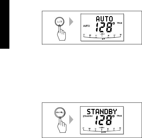
Engaging the autopilot (Auto mode)
To engage the autopilot:
1.Steady the boat on the required heading.
2.Press auto:
• in Auto mode, the display shows the locked autopilot heading
2 Basic Operation
D3560-3
CAUTION:
Autopilot course control makes it easier to sail a boat, but it is NOT a substitute for good seamanship. ALWAYS maintain a permanent watch by the helm.
Disengaging the autopilot (Standby mode)
Press standby to disengage the autopilot:
•in Standby mode, the display shows the boat’s current compass heading.
•the last heading is memorized and can be recalled (see page 11).
D3561-3

Chapter 2: Basic Operation |
7 |
Changing course in Auto mode
In Auto mode, use the -1 and -10 (port) and +1 and +10 (starboard) keys to change the locked heading in steps of 1° or 10°. For example: press -10 three times for a 30° course change to port.
Port |
Starboard |
or |
or |
D3320-2
Adjusting performance – Type 150G/400G
The main way you can adjust the performance of Type 150G/400G (GyroPlus) autopilot systems is by changing the response level. This is the only user adjustment you should need to make to the autopilot on a regular basis.
The response level controls the relationship between the autopilot’s course keeping accuracy and the amount of helm/drive activity.
Type 150G and 400G autopilot systems have 9 levels of response:
•level 1 gives the least pilot activity to conserve power, but may compromise short-term course-keeping accuracy
•levels 4 to 6 should give good course keeping under normal operating conditions – with crisp, well controlled turns but without being over-aggressive
•level 9 gives the tightest course keeping and greatest rudder activity, but may lead to a rough passage in open waters as the autopilot may ‘fight’ the sea
When you require extra tight course keeping (e.g. for pilotage in confined and sheltered waters), increase the setting. If you want to minimize drive activity and conserve battery power, decrease
the setting.
Operation Basic 2
2 Basic Operation
8 |
ST6001+ Autopilot Control Unit - Owner’s Handbook |
You can adjust the default response level in either User or Dealer Calibration (see page 85). This determines the default power-up response level.
However, when using your autopilot on a day-to-day basis, you can make temporary adjustments to the response level. By doing this you can match autopilot performance to different conditions.
Temporary changes to response – Type 150G/400G
With these points in mind, you should use the following procedure to make temporary adjustments to the response level when required:
1.Display the RESPONSE screen by pressing the -1 and +1 keys together momentarily.
Decrease |
Increase |
response |
response |
D5452-1
Note: The RESPONSE screen is set as a default data page (see
page 81) so you can also access it by pressing disp and then scrolling through the data pages.
2.Press -1 or +1 to change the response level.
3.Press disp or wait for 5 seconds to return to the previous display.
Note: You will lose these temporary changes to response level whenever the system is powered off. You can make permanent adjustments in User or Dealer Calibration (see page 85).
Adjusting performance – Types 150/400 and 100/300
To adjust the performance of Type 150/400 (non-GyroPlus) and Type 100/300 autopilot systems you can change the response level.

Chapter 2: Basic Operation |
9 |
Response level – Types 150/400 and 100/300
The response level controls the relationship between the autopilot’s course keeping accuracy and the amount of helm/drive activity.
You can adjust the default response level in either User or Dealer Calibration (see page 85). This determines the default power-up response level.
However, when using your autopilot on a day-to-day basis, you will need to make temporary adjustments to the response level. By doing this you can match autopilot performance to different conditions.
Type 150/400 (without GyroPlus) and Type 100/300 autopilot systems have three different response levels:
•Response Level 1: AutoSeastate on (Automatic deadband)
This setting causes the autopilot to gradually ignore repetitive boat movements and only react to true variations in course. This provides the best compromise between power consumption and course keeping accuracy, and is the default calibration setting.
•Response Level 2: AutoSeastate off (Minimum deadband)
This setting provides tighter course keeping. However, this results in increased power consumption and drive unit activity.
•Response Level 3: AutoSeastate off + yaw damping
This setting provides the tightest possible course keeping by introducing counter rudder yaw damping. You can adjust the counter rudder setting in Dealer Calibration (see page 91)
To make a temporary change to the response setting:
1.Display the RESPONSE screen by pressing the -1 and +1 keys together momentarily.
2.Press -1 or +1 to change the response between levels 1 to 3.
3.Press disp or wait for 5 seconds to return to the previous display.
Note: You will lose these temporary changes to response level whenever the system is powered off. You can make permanent adjustments in User or Dealer Calibration (see page 85).
Operation Basic 2
10 |
ST6001+ Autopilot Control Unit - Owner’s Handbook |
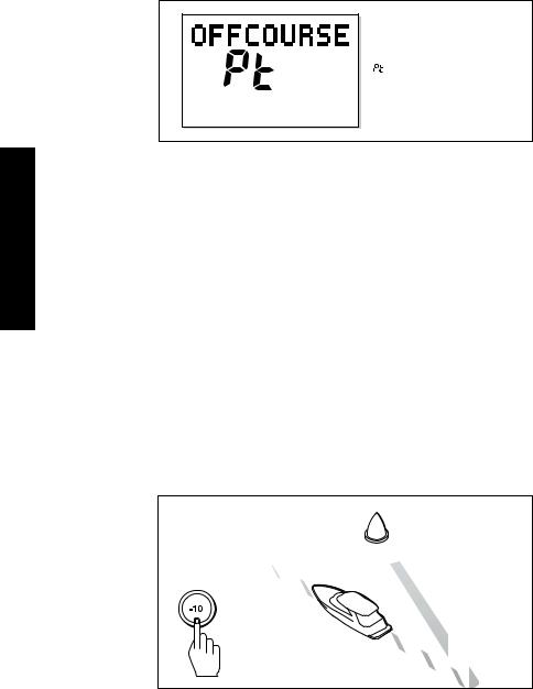
Off Course warning
2 Basic Operation
= deviation to port

 = deviation to starboard
D3315-2
The ST6001+ activates the OFF COURSE warning when the boat has been off course from the locked heading by more than the specified angle* for longer than 20seconds. It shows whether the deviation is to port or starboard.
Note: * You can adjust this specified off course angle in Dealer Calibration (see page 93).
1.To cancel the off course warning, press standby to return to hand steering.
2.Check whether your boat is carrying too much sail, or whether the sails are badly balanced. You can usually significantly improve course keeping by improving the sail balance.
Note: The ST6001+ also clears the warning if the heading recovers, if you change the course, or if you change the operating mode.
Dodging obstacles and then resuming course
To avoid an obstacle when your boat is under autopilot control, you can dodge the obstacle and then resume your previous course.
Dodging an obstacle
Obstacle
Original
course
Dodge
D3303-2P

Chapter 2: Basic Operation |
11 |
Dodging an obstacle
1.Select a course change in the appropriate direction. For example, press -10 three times for a 30° dodge to port.
2.When safely clear of the obstacle, you can either:
•reverse the previous course change (for example, press +10 three times), or
•return to the previous locked heading (LAST HDG) as described below
Returning to the previous heading (LAST HDG?)
When the boat is in Auto mode and you have steered the boat away from the selected locked heading for any reason (for example, to execute a dodge maneuver), you can return to the previous locked heading (the most recent heading held for 20 seconds). To do this:
1.Press auto for 1 second. The display flashes and shows the previous locked heading (LAST HDG?) for 10 seconds. The direction-to-steer indicator shows the direction the boat will turn.
2.To accept this heading, and resume this course, press auto when the display is flashing.
Note: If you do not press auto while the display is flashing, the autopilot will maintain the current heading.
Returning to last heading
Resumed |
Obstacle |
|
course |
||
|
1 SECOND
Original
course
Dodge
Operation Basic 2
D5499-1

2 Basic Operation
12 |
ST6001+ Autopilot Control Unit - Owner’s Handbook |
Using sail boat features
Automatic tack (AutoTack)
The ST6001+ has a built in automatic tack facility (AutoTack) that turns the boat through 100° in the required direction. If you have set the vessel type to SAIL BOAT, you can adjust the default AutoTack angle in User or Dealer calibration (see page 83).
•to AutoTack to port: press the -1 and -10 keys together
•to AutoTack to starboard: press the +1 and +10 keys together
CAUTION:
When making major course changes, the trim on the boat may change substantially. Because of this, the autopilot may take some time to settle accurately onto the new course.
AutoTack - Port |
AutoTack - Starboard |
|
|
Wind |
Wind |
|
|
|
AutoTack |
AutoTack |
angle |
angle |
D5399-1
Preventing accidental gybes
Note: For the gybe inhibit feature to work, the autopilot needs suitable wind information (see page 23).
The gybe inhibit feature stops the boat from performing an AutoTack away from the wind – this will prevent accidental gybes. On Type 150/150G and 400/400G autopilots, you can turn off this feature if required:

Chapter 2: Basic Operation |
13 |
•with gybe inhibit on:
•you will be able to perform an AutoTack into the wind
•to prevent accidental gybes, the autopilot will prevent the boat from performing an AutoTack away from the wind
•with gybe inhibit off:
•you can perform an AutoTack into or away from the wind.
Note: Gybe inhibit is switched on as a default. On Type 150/150G and Type 400/400G autopilots you can switch it off in User or Dealer Calibration (see page 83).
Gusty conditions
In gusty conditions, the course may tend to wander slightly, particularly if the sails are badly balanced. If you take the following precautions, the autopilot will be able to maintain competent control even in gale force conditions:
•You can significantly improve course keeping by improving the sail balance:
•do not allow the boat to heel over excessively
•ease the mainsheet traveller to leeward to reduce heeling and weather helm
•if necessary, reef the mainsail a little early
•In very strong winds and large seas, you should avoid sailing with the wind dead astern:
•ideally, bring the wind at least 30° away from a dead run
•in severe conditions, you may also need to remove the mainsail and sail under headsail only
Operation Basic 2

2 Basic Operation
14 |
ST6001+ Autopilot Control Unit - Owner’s Handbook |
2.3 Adjusting display/keypad lighting
Note: When the display lighting is off, the control unit illuminates the keys at a courtesy level.
To adjust the display and keypad lighting:
1.Press disp for 1 second from any mode to access the LAMP screen and turn on the lights.
2.Press the disp key to cycle through the possible illumination settings: LAMP 3 (the brightest setting), LAMP 2, LAMP 1, OFF, LAMP 1, LAMP 2, LAMP 3 and so on:
• as you change the setting, the illumination on any other
SeaTalk instruments or control units will also change
.
SECOND
D3313-3
3.The display automatically returns to the previous mode if you do not press a key for 10 seconds:
•if you press another mode key within 10 seconds you will select the mode assigned to that key (for example: auto selects Auto mode, standby selects Standby mode)
Note: You can also adjust the lighting level from any other SeaTalk instrument or control unit.
Note: When you switch off the unit you lose any changes you have made to the lighting level.

Chapter 3: Advanced Operation |
15 |
Chapter 3: Advanced Operation
The sections in this chapter explain how to use the more advanced functions on your autopilot:
3.1 |
Using Track mode |
|
|
Tracking between waypoints created on navigation |
page 16 |
||
|
equipment connected to the autopilot system. |
|
|
|
|
|
|
|
|
|
|
3.2 |
Using Wind Vane mode – sail boats |
|
|
Using the autopilot to maintain a course relative to a |
page 23 |
||
|
true or apparent wind angle. |
|
|
|
|
|
|
|
|
|
|
3.3 |
Adjusting the rudder gain |
|
|
Explains how to adjust the rudder gain setting (mainly |
page 27 |
||
|
applies to non-GyroPlus Type 150/400 systems). |
|
|
|
|
|
|
|
|
|
|
|
Displaying data pages |
|
|
3.4 |
Describes how to use data pages to display SeaTalk and |
page 29 |
|
NMEA information on the control unit. This section also |
|||
|
|
||
|
explains the Watch timer feature. |
|
|
|
|
|
Note: If you are using the control unit with a non-150/400 autopilot system, refer to the notes in the Appendix.
Operation Advanced 3

3 Advanced Operation
16 |
ST6001+ Autopilot Control Unit - Owner’s Handbook |
3.1 Using Track mode
Note: You can only use Track mode if you have connected the autopilot to a suitable navigation system providing SeaTalk or NMEA navigation information.
The autopilot system can receive track information from either:
•a SeaTalk navigation instrument or chartplotter (see page 49 for information on connecting to SeaTalk), or
•a non-SeaTalk navigation system transmitting data in the NMEA 0183 format (see page 50 for information on connecting NMEA equipment)
In Track mode, the autopilot maintains a track between waypoints created on the navigation system. The autopilot makes any course changes necessary to keep your boat on track, automatically compensating for tidal streams and leeway.
Selecting Track mode
CAUTION:
When you enter Track mode, the autopilot will bring the boat onto the track in a controlled way. The closer the boat is to the correct heading and track, the quicker the autopilot will settle the boat onto the new course. To avoid an unexpected turn, approximately align the boat with the required track before entering Track mode.
To select Track mode:
1.Start with the autopilot in Auto mode.
2.Press track to enter Track mode.
3.Wait for the Waypoint Advance warning to sound. The display will show the bearing to the next planned waypoint and the direction the boat will turn to reach this waypoint.
4.Check that it is safe for the boat to turn onto the new course.
5.Press the track key:
•the autopilot will turn the boat onto the new course in a controlled way
•the display shows the heading required to achieve the required track

Chapter 3: Advanced Operation |
17 |
Note: The closer the boat is to the correct heading and track when you press track, the quicker the autopilot will bring the boat onto the new course. If the boat is more than 0.3 nm from the track, the Large Cross Track Error warning will sound (see page 17).
Automatic track acquisition
From auto mode, press track to enter Track mode: |
Then press track again to turn boat to waypoint: |
||||||||
|
|
|
|
Waypoint |
|
|
Waypoint |
||
|
|
|
|
|
|
||||
|
|
|
|
at 270˚ |
|
|
at 270˚ |
||
|
|
|
|
|
|
|
|
|
|
Current |
|
|
|
Previous |
|
|
|
||
heading |
|
|
|
heading |
|
|
|
||
|
|
|
|
||||||
|
|
|
|
|
|
|
|
|
|
|
|
|
|
|
|
|
|
|
|
|
|
|
|
|
|
|
|
|
|
|
|
|
|
|
|
|
|
|
|
|
|
|
|
|
|
|
|
|
|
D5414-1
Exiting Track mode
You can exit Track mode and return to Auto or Standby mode by:
•pressing auto to return to Auto mode
•pressing standby to steer manually in Standby mode
Cross track error
Cross track error (XTE) is the distance between the current position and a planned route. The autopilot receives the cross track error information from the navigation equipment, and displays the XTE in nautical miles (nm), statute miles (SM) or kilometres.
If the cross track error is greater than 0.3 nm, the ST6001+ will sound the Large Cross Track Error warning and show whether you are to the port (Pt) or starboard (Stb) of the planned track.
Operation Advanced 3
Loading...