


Ray430
Loudhailer
Owner’s Handbook
PURPOSE
THIS MANUAL CONTAINS IMPORTANT INFORMATION ON THE INSTALLATION,
OPERATION AND MAINTENANCE OF YOUR EQUIPMENT
Raymarine products are supported by a network of Authorized Service Representatives. For product information, you may contact the following regional centers:
United States………………………………………. Raymarine, Inc.
21 Manchester Street Merrimack
New Hampshire
USA 03054-4801 Telephone:603-881-5200 Fax: 603-862-4756
Europe…………………………………………….. Raymarine plc Robinson Way, Anchorage Park Portsmouth Hampshire P03 5TD United Kingdom
Telephone +44 |
(0)23 9269 3611 |
|
Fax |
+44 |
(0)23 9269 4642 |
IMPORTANT NOTICE
THIS DEVICE IS ONLY AN AID TO BOATING SAFETY AND NAVIGATION. ITS PERFORMANCE CAN BE AFFECTED BY MANY FACTORS INCLUDING EQUIPMENT FAILURE OR DEFECT, ENVIRONMENTAL CONDITIONS, AND IMPROPER HANDLING OR USE. IT IS THE USER’S RESPONSIBILITY TO EXERCISE COMMON PRUDENCE AND NAVIGATIONAL JUDGMENT. THIS DEVICE SHOULD NOT BE RELIED ON AS A SUBSTITUTE FOR SUCH PRUDENCE AND JUDGMENT.
TABLE OF CONTENTS
SECTION 1 |
GENERAL |
|
1.1 |
INTRODUCTION ................................................................................... |
1-1 |
1.2 |
EQUIPMENT FEATURES ..................................................................... |
1-1 |
1.3 |
SPECIFICATIONS.................................................................................. |
1-2 |
SECTION 2 |
INSTALLATION |
|
2.1 |
UNPACKING AND INSPECTION........................................................ |
2-1 |
2.2 |
EQUIPMENT SUPPLIED....................................................................... |
2-1 |
2.2.1 |
Optional Accessories ......................................................................... |
2-2 |
2.3 |
STORAGE ............................................................................................... |
2-2 |
2.4 |
PLANNING THE INSTALLATION ...................................................... |
2-3 |
2.4.1 |
Mounting Options .............................................................................. |
2-5 |
2.5 |
ELECTRICAL CONNECTION .............................................................. |
2-5 |
2.5.1 |
DC Power Connections...................................................................... |
2-5 |
2.5.2 |
Intercom Speaker(s)........................................................................... |
2-6 |
2.5.3 |
Hailer Horn(s) .................................................................................... |
2-7 |
2.5.4 |
Connection of Burglar Alarm ............................................................ |
2-7 |
2.5.5 |
Remote Microphone........................................................................... |
2-7 |
2.5.6 |
Auxiliary lnput................................................................................... |
2-8 |
2.5.7 |
Connection of an External Speaker.................................................... |
2-8 |
SECTION 3 |
OPERATION |
|
3.1 |
INTRODUCTION ................................................................................... |
3-1 |
3.2 |
CONTROLS AND LCD DISPLAY........................................................ |
3-1 |
3.2.1 |
Controls.............................................................................................. |
3-1 |
3.2.2 |
LCD Display ...................................................................................... |
3-3 |
3.3 |
OPERATING PROCEDURES................................................................ |
3-5 |
3.3.1 |
The Power Switch/Dimmer Control .................................................. |
3-5 |
3.3.2 |
Volume Control (Hail & Listen)........................................................ |
3-5 |
3.3.3 |
Hail Mode .......................................................................................... |
3-6 |
3.3.4 |
Intercom Operation ............................................................................ |
3-6 |
i
3.3.5 |
Fog Horn Mode.................................................................................. |
3-8 |
3.3.6 |
Aux Mode .......................................................................................... |
3-13 |
SECTION 4 |
TECHNICAL DESCRIPTION |
|
4.1 |
BLOCK DIAGRAM................................................................................ |
4-1 |
SECTION 5 |
MAINTENANCE |
|
5.1 |
GENERAL............................................................................................... |
5-1 |
5.1.1 |
Product and Customer Service........................................................... |
5-1 |
5.2 |
PREVENTATIVE MAINTENANCE ..................................................... |
5-1 |
5.3 |
ADJUSTMENT ....................................................................................... |
5-2 |
5.3.1 |
Test Equipment .................................................................................. |
5-2 |
5.3.2 |
Listen Output Adjustment.................................................................. |
5-2 |
5.3.3 |
Intercom Output Adjustment ............................................................. |
5-3 |
5.3.4 |
Level Meter Adjustment .................................................................... |
5-3 |
SECTION 6 |
PARTS LIST & DRAWINGS |
|
6.1 |
PARTS LIST............................................................................................ |
6-1 |
6.2 |
ASSEMBLY DRAWING........................................................................ |
6-8 |
6.3 |
PARTS LIST FOR ASSEMBLY DRAWING ........................................ |
6-9 |
6.4 |
INTERNAL WIRING DIAGRAM.......................................................... |
6-11 |
6.5 |
LINEAR A SCHEMATIC DIAGRAM................................................... |
6-12 |
6.6 |
LINEAR B SCHEMATIC DIAGRAM................................................... |
6-13 |
6.7 |
LINEAR A PCB PARTS LAYOUT........................................................ |
6-14 |
6.8 |
LINEAR B PCB PARTS LAYOUT........................................................ |
6-14 |
6.9 |
CPU PCB SCHEMATIC DIAGRAM..................................................... |
6-15 |
6.10 |
CPU PCB PARTS LAYOUT .................................................................. |
6-16 |
ii

SECTION 1
GENERAL DESCRIPTION
1.1INTRODUCTION
Congratulations on your purchase of the RAY430 Multifunction Loudhailer.
The RAY430 Loudhailer is a multipurpose device that may be used as a ship-to-shore hailer, ship-to- ship hailer, foghorn, audio amplifier, intercom, and/or alarm system.
As a loudhailer, the RAY430 amplifies your voice up to a 30 watt level, for hailing through the hailing horn speaker, and when listening for replies, amplifies the incoming sounds to the desired listening level. If an additional (optional) horn is added to the system, the loudhailer output can be switched to either or both of the hailing horn positions by the front panel control.
To verify your ownership and warranty registration, you should take a few minutes and fill out your warranty registration card found just inside the front cover of this manual. It is very important that you take the time to fill this card out. The warranty registration card should be returned to the factory immediately after your purchase in order to receive full warranty benefits.
Section 5 in this manual provides further information on obtaining Customer Service and Product Support which is available to you as a valued customer.
1.2EQUIPMENT FEATURES
The RAY430 is designed and manufactured to provide ease of installation and operation with excellent reliability. Some of the important built-in features of the equipment are listed below.
The loudhailer horns(s) are used as sound dispersal points when the RAY430 is used as a foghorn so that the full 30 watt output of the unit can be employed.
In the foghorn mode any of six programmed foghorn patterns can be automatically generated. They are: Underway, Stopped, Sail, Tow, Anchored, and Aground.
INTERCOM — Provides 2-way communication between the display unit and up to 4 connected remote units, which can also originate a call to the display unit.
AUXILIARY MODE — Allows the selective or simultaneous transmission of an external audio input to all stations. For entertainment, the external audio can be a cassette deck, radio, or CD player. For business, it can also be any other instrument having an external audio output, such as the output from a VHF or SSB radiotelephone.
1-1
EXTERNAL ALARM CONNECTION — For external systems or security alarm sensors.
EASY TO USE — An ideal arrangement, the RAY430 has an illuminated keyboard and LCD which clearly shows all selected stations and operating modes.
DURABLE, WATERPROOF CONSTRUCTION — With rugged gaskets and our heavy-duty microphone the RAY430 is built to survive in the toughest marine environments.
SILICONE RUBBER KEYBOARD — Has backlighting for easy night-time viewing and operation.
OPTIONAL FLUSH-MOUNT KIT — For attractive customized mounting into overhead instrument cabinets or in the console of your bridge.
1.3SPECIFICATIONS
Dimensions: |
4 3/4 x 9 3/16 x 4 1/2 inches (121 x 234 x 114 mm) |
|
Height x Width x Depth |
Weight |
Approximately 1.9 Kg (4.3 lbs) |
Power supply |
13.6 VDC nominal (±20%) 5 amps or less |
Audio Output |
Hail Spkr 30W |
|
Intercom Spkr 4.5W |
|
Ext. Spkr 4.5W |
|
Int. Spkr 2.5W |
Output impedances |
Hail Spkr 8 ohms |
|
Intercom Spkr 8 ohms |
|
Ext. Spkr 8 ohms |
Input Impedance |
Mic. Impedance 600 ohms |
|
Aux Impedance 10K ohms |
Input Sensitivity |
Mic. Sensitivity -40 dB 3dB (at 1KHz) |
|
Aux Sensitivity -10 dB 3dB (at 1KHz) |
|
SP/Mic Sensitivity 6mV RMS ±20% |
Frequency Response |
Hail Mode 100Hz to 8KHz 5dB |
|
Listen Mode 100Hz to 8KHz 5dB |
|
Aux Mode 100Hz to 20KHz 5dB |
Distortion Factor |
Hail Mode 10% or less (at 1KHz 30W) |
|
Listen Mode 10% or less (at 1KHz 5W) |
|
Aux Mode 10% or less (at 1KHz 30W) |
Signal to Noise Ratio |
Hail Mode 60dB or more (at 1KHz) |
|
Listen Mode 60dB or more (at 1KHz) |
|
Aux Mode 60dB or more (at 1KHz) |
Horn Frequency |
500Hz ± 50Hz |
1-2

SECTION 2
INSTALLATION
2.1UNPACKING AND INSPECTION
Use care when unpacking your new RAY430 from the shipping carton to prevent damage to the contents. It is also a good practice to save the carton and the interior packing material. The original packing material should be used in the unlikely event that it becomes necessary in the future to return the unit for service.
2.2EQUIPMENT SUPPLIED
The following is a list of the standard equipment included with your RAY430 Loudhailer.
Equipment Name |
Part No. |
|
|
RAY430 Loudhailer Unit |
M95997 |
|
|
Hailer Horn |
M95435 |
|
|
Microphone |
G263596-2 |
|
|
Microphone Mounting Bracket |
G263596-3 |
|
|
Mounting Yoke |
G263596-4 |
|
|
Bridge Card |
G263647-4 |
|
|
Instruction Manual |
G263647-5 |
|
|
|
|
2-1
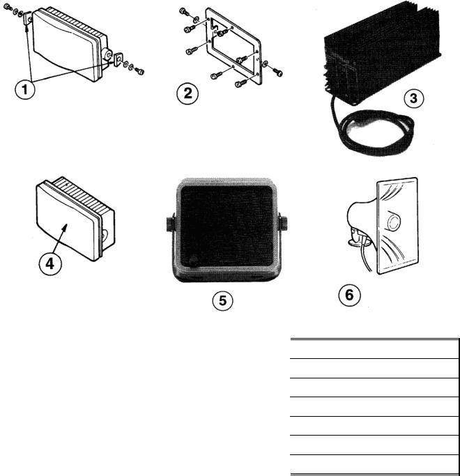
2.2.1 Optional Accessories
Item # |
Description |
Part No. |
|
|
|
1 |
Console Mounting Kit (Flush Mount) |
M95990 |
|
|
|
2 |
Console Mounting Kit (Trim Ring Style) |
M95995 |
|
|
|
3 |
Power Supply, 115/220 VAC to 1 2 VDC |
M59733 |
|
|
|
4 |
Sun Cover |
G263696- 1 |
|
|
|
5 |
Intercom Speaker |
M95998 |
|
|
|
6 |
Hailer Horn |
M95435 |
|
|
|
|
|
|
2.3STORAGE
After all of the components have been unpacked and inspected, they should be replaced in their shipping containers and stored in a dry place until they are to be installed. The storage area should be dry, well-ventilated and not subjected to temperature extremes below -20°C or above +55 °C.
2-2
2.4PLANNING THE INSTALLATION
When planning the location for your RAY430 to be installed, the following conditions should be considered to insure dependable and trouble-free operation.
1)The mounting location should be easily accessible to allow easy operation of the front panel and provide the best viewing angle of the display.
2)There should be adequate ventilation.
3)A sufficient space should be secured behind the unit to allow all cable connections to the rear panel terminal strip.
4)The mounting place should be located as near to the power source as possible.
5)The selected location should be isolated away from devices that may cause offending noise or interference, such as motors, steering cables and generators.
6)Generally speaking, the Loudhailer should be protected from prolonged direct exposure to rain and salt spray. It is a good practice to protect this valuable equipment as much as possible.
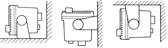
The unit can be conveniently mounted on a chart table, bulkhead, overhead or any other desired place. (Refer to Figure 2- 1 for typical locations and mounting configurations.)
(table top mount) |
(bulkhead mount) |
(overhead mount) |
Figure 2-1 Examples of installation
2-3
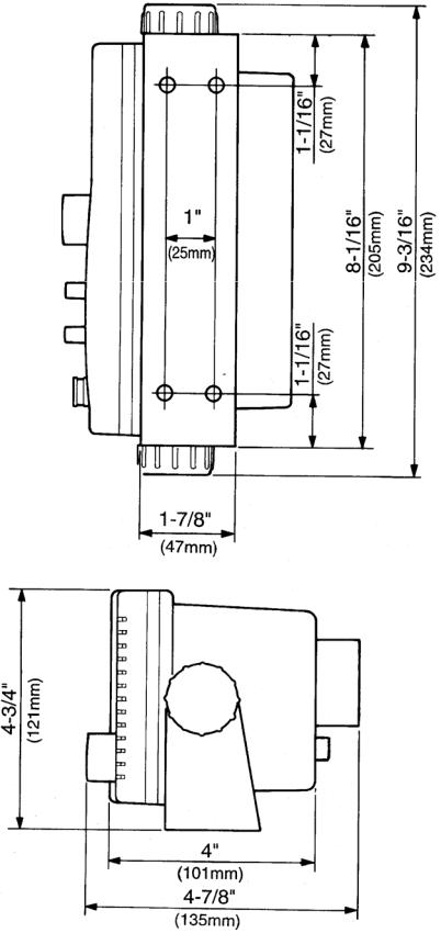
Figure 2-2 Outline and Mounting Dimensions
2-4
2.4.1Mounting Options
Flush-mounting your RAY430 can be performed using one of the methods shown below.
Console Mounting Kit (Trim Ring Style-M95995) |
Console Mounting Kit (M95990) |
Figure 2-3
2.5ELECTRICAL CONNECTION
Figure 2-4 RAY430 Rear Panel
CAUTION
DO NOT INSTALL THIS RADIO ON VESSELS WITH POSITIVE
GROUND BATTERY SYSTEMS.
2.5.1DC Power Connections
The RAY430 is intended for use on vessels with 12 VDC power systems and can operate as long as the DC supply is regulated between 10.8 and 16 VDC.
The input power connections are made at the terminal strip on the rear of the RAY430 unit at the terminals labeled "13.6V" "+" and "–". See Figure 2-8 on page 2-9 for the exact locations.
2-5
The power leads should normally be routed to the ship’s DC power distribution panel on larger boats. The RAY430 is fused at 10 amps so connection to a 10 amp or (maximum of) 15 amp circuit breaker is recommended. On smaller vessels the power leads may be connected directly to the main battery, isolation switch, or circuit breaker. For best noise isolation from other shipboard electronics avoid grouping the loudhailer power connections with radar, radio, or echo sounder power leads together on the same circuit breaker.
Although the RAY430’s power consumption is only 65 watts (maximum), if you find that the power cable leads need to be extended more than 10 feet, the wire size of the leads should be in-creased accordingly to minimize line losses. For runs of 20-35 feet #12 AWG is recommended, remember to always solder all connections on all your power cord additions.
Observe proper polarity! The wire connected to the positive (+) terminal must be connected to the positive point of the DC power source; The wire connected to the Negative (—) terminal of the terminal strip must be connected to the negative point of the DC power source. If the power leads are accidentally reversed, the 10 Amp fuse will blow. If this happens, recheck the polarity of the connections with a voltmeter (VOM) and, if necessary, reverse the leads for proper connection. Then replace the 10 amp fuse in the power cord.
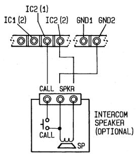
2.5.2Intercom Speaker
Up to four intercom station speakers (optional) can be connected to the intercom speaker terminals labeled IC1-IC4 on the terminal block. The optional intercom speakers M95998 are 8 ohms and indude “CALL” buttons. Stations 1, 2, 3 and 4, should be connected to the terminal block accordingly so that they will correspond to the desired Intercom station selections.
Connect one of the speaker lines to terminal 2, the other line to the GND terminal (on the right side of the terminal block). The “call” line should be connected to the terminal 1.
Figure 2-5
2-6
2.5.3Hailer Horn(s)
The outside hailer horns should be mounted facing away from the display unit to prevent feedback problems using the universal swivel mount provided. High gain audio amplifier circuits “hailers” are susceptible to high frequency audio oscillations (a.k.a. feedback). It is highly recommended that before permanently mounting the hailing horn, that the HAIL feature is tested with the horn in the desired location. This should be done to ensure optimum performance. Generally speaking the horn should be mounted as far away as possible and facing away from the RAY430 base unit. It should be pointed in the opposite direction of the RAY430 microphone as you are speaking into it.
Connection to the horn(s) should be made with No. 1 8 or larger, stranded, twisted pair copper wire. The two-conductor cable chosen should be suitable for external all-weather use.
Electrical connections from the deck horn(s) are made on the rear panel terminal strip at either the FWD or AFT terminal point, depending on the location of the speaker you are connecting.
For connection to FWD, connect the deck horn to terminals “FWD” 1 and 2. For connection to AFT, connect the deck horn to terminals “AFT’ 1 and 2.
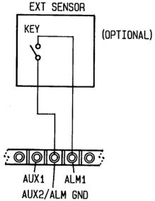
2.5.4Connection of Burglar Alarm
By connecting an external alarm sensor using a normally open type of switch (not supplied) to the ALM terminals, this unit can be used as a burglar alarm in the Fog ALM mode (burglar alarm).
When the sensor connected at terminals 1 and 2 (AUX) of this terminal block become shorted (closed), the alarm function becomes activated and the yelp signal will sound at the maximum volume through the forward deck hailer horn speaker.
Figure 2-6
2.5.5 Remote Microphone
An external microphone connection is located on the rear panel terminal strip. This may be used if you desire to operate hailing functions from a secondary station.
2-7
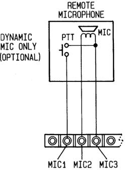
Figure 2-7
2.5.6 Auxiliary Input
Your RAY430 has been designed to allow you to amplify the audio from your VHF radiotelephone or any other external audio output (i.e. AM/FM radio, CD player) through your intercom or deck speaker stations. This external audio input can be connected at the auxiliary input terminals 1 and 2.
2.5.7Connection of an External Speaker
In situations where the main unit is distant from the operator and the noise level is very high, it may be difficult to hear your RAY430 clearly. By connecting an external (8 ohms, 5 watts or more) speaker, the sound level can be increased for improved listening capability. When an external speaker is connected at the external speaker jack, the internal speaker is automatically disconnected. The connector, a mini phone plug, for the external speaker is supplied with your RAY430 for your convenience.
2-8

Figure 2-8 RAY430 Electrical Connections
2-9
2-10
SECTION 3
OPERATION
3.1INTRODUCTION
While the operation of the RAY430 is easy and straight forward, the operator who is familiar with the functions and understands the layout of the front panel controls will be able to obtain the best performance from their equipment.
Following is a description of the front panel controls of the RAY430 loudhailer.
3.2CONTROLS AND LCD DISPLAY
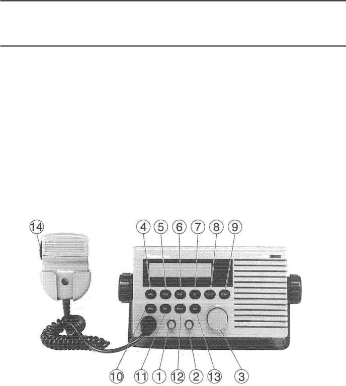
Refer to Figure 3-1 for familiarization with the following controls:
Figure 3-1 RAY430 Front Panel
3.2.1Controls
1)On/Off & Dimmer Control Knob:
This control turns the RAY430 On and Off, and rotating the control clockwise increases the backlighting level of the LCD display.
3-1
 Loading...