


RF COMMUNICATIONS PRODUCTS
SA612A
Double-balanced mixer and oscillator
Product specification |
1997 Nov 07 |
|
Replaces data of September 17, 1990 |
||
|
||
IC17 Data Handbook |
|
Philips Semiconductors
Philips Semiconductors |
Product specification |
|
|
|
|
|
|
|
Double-balanced mixer and oscillator |
SA612A |
|
|
|
|
|
|
|
DESCRIPTION
The SA612A is a low-power VHF monolithic double-balanced mixer with on-board oscillator and voltage regulator. It is intended for low cost, low power communication systems with signal frequencies to
500MHz and local oscillator frequencies as high as 200MHz. The mixer is a ªGilbert cellº multiplier configuration which provides gain of 14dB or more at 45MHz.
The oscillator can be configured for a crystal, a tuned tank operation, or as a buffer for an external L.O. Noise figure at 45MHz is typically below 6dB and makes the device well suited for high performance cordless phone/cellular radio. The low power consumption makes the SA612A excellent for battery operated equipment. Networking and other communications products can benefit from very low radiated energy levels within systems. The SA612A is available in an 8-lead dual in-line plastic package and an
8-lead SO (surface mounted miniature package).
FEATURES
•Low current consumption
•Low cost
•Operation to 500MHz
•Low radiated energy
•Low external parts count; suitable for crystal/ceramic filter
•Excellent sensitivity, gain, and noise figure
PIN CONFIGURATION
D, N Packages
|
|
|
|
|
INPUT A |
1 |
|
8 |
VCC |
|
|
|
|
|
INPUT B |
2 |
|
7 |
OSCILLATOR |
|
|
|
|
|
GND |
3 |
|
6 |
OSCILLATOR |
|
|
|
|
|
OUTPUT A |
4 |
|
5 |
OUTPUT B |
|
|
|
|
|
SR00098
Figure 1. Pin Configuration
APPLICATIONS
•Cordless telephone
•Portable radio
•VHF transceivers
•RF data links
•Sonabuoys
•Communications receivers
•Broadband LANs
•HF and VHF frequency conversion
•Cellular radio mixer/oscillator
ORDERING INFORMATION
DESCRIPTION |
TEMPERATURE RANGE |
ORDER CODE |
DWG # |
|
|
|
|
8-Pin Plastic Dual In-Line Plastic (DIP) |
-40 to +85°C |
SA612AN |
SOT97-1 |
|
|
|
|
8-Pin Plastic Small Outline (SO) package (Surface-Mount) |
-40 to +85°C |
SA612AD |
SOT96-1 |
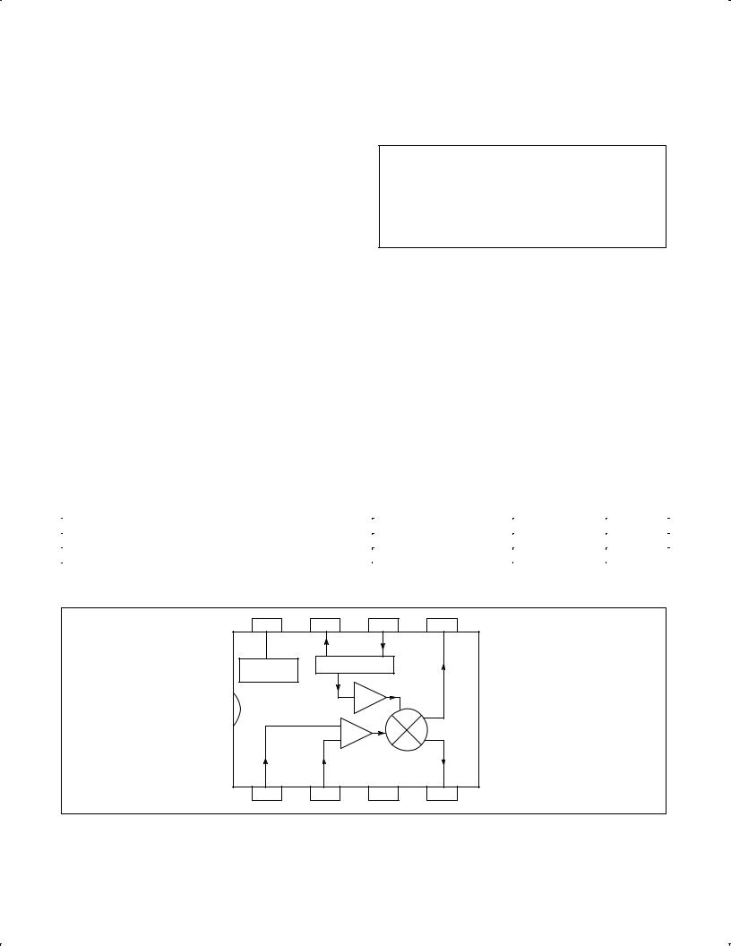
BLOCK DIAGRAM
8 |
7 |
6 |
5 |
VCC |
|
|
|
VOLTAGE |
|
OSCILLATOR |
|
REGULATOR |
|
|
|
|
|
GROUND |
|
1 |
2 |
3 |
4 |
SR00099
Figure 2. Block Diagram
1997 Nov 07 |
2 |
853-0391 18662 |

Philips Semiconductors |
Product specification |
|
|
|
|
Double-balanced mixer and oscillator |
SA612A |
|
|
|
|
ABSOLUTE MAXIMUM RATINGS
SYMBOL |
PARAMETER |
RATING |
UNIT |
|
|
|
|
VCC |
Maximum operating voltage |
9 |
V |
TSTG |
Storage temperature |
-65 to +150 |
°C |
TA |
Operating ambient temperature range SA612A |
-40 to +85 |
°C |
AC/DC ELECTRICAL CHARACTERISTICS
TA=25°C, VCC = 6V, Figure 3
SYMBOL |
PARAMETER |
TEST CONDITION |
|
LIMITS |
|
UNIT |
|
|
|
|
|||||
Min |
Typ |
Max |
|||||
|
|
|
|
||||
|
|
|
|
|
|
|
|
VCC |
Power supply voltage range |
|
4.5 |
|
8.0 |
V |
|
|
DC current drain |
|
|
2.4 |
3.0 |
mA |
|
|
|
|
|
|
|
|
|
fIN |
Input signal frequency |
|
|
500 |
|
MHz |
|
fOSC |
Oscillator frequency |
|
|
200 |
|
MHz |
|
|
Noise figured at 45MHz |
|
|
5.0 |
|
dB |
|
|
|
|
|
|
|
|
|
|
Third-order intercept point at 45MHz |
RFIN=-45dBm |
|
-13 |
|
dBm |
|
|
Conversion gain at 45MHz |
|
14 |
17 |
|
dB |
|
|
|
|
|
|
|
|
|
RIN |
RF input resistance |
|
1.5 |
|
|
kΩ |
|
CIN |
RF input capacitance |
|
|
3 |
|
pF |
|
|
Mixer output resistance |
(Pin 4 or 5) |
|
1.5 |
|
kΩ |
DESCRIPTION OF OPERATION
The SA612A is a Gilbert cell, an oscillator/buffer, and a temperature compensated bias network as shown in the equivalent circuit. The
Gilbert cell is a differential amplifier (Pins 1 and 2) which drives a balanced switching cell. The differential input stage provides gain and determines the noise figure and signal handling performance of the system.
The SA612A is designed for optimum low power performance. When used with the SA614A as a 45MHz cordless phone/cellular
radio 2nd IF and demodulator, the SA612A is capable of receiving -119dBm signals with a 12dB S/N ratio. Third-order intercept is typically -15dBm (that's approximately +5dBm output intercept because of the RF gain). The system designer must be cognizant of this large signal limitation. When designing LANs or other closed systems where transmission levels are high, and small-signal or signal-to-noise issues not critical, the input to the SA612A should be appropriately scaled.
1997 Nov 07 |
3 |

Philips Semiconductors |
Product specification |
|
|
|
|
Double-balanced mixer and oscillator |
SA612A |
|
|
|
|
TEST CONFIGURATION
|
0.5 to 1.3μH |
|
|
|
|
22pF |
|
|
1nF |
34.545MHz THIRD OVERTONE CRYSTAL |
|
5.5μH |
10pF |
||
|
VCC
6.8μF 


 100nF
100nF
10nF |
8 |
7 |
6 |
5 |
|
|
|
|
150pF |
|
|
|
|
OUTPUT |
|
|
|
612A |
1.5 to |
|
|
|
44.2μH |
|
|
|
|
|
330pF |
|
1 |
2 |
3 |
4 |
120pF |
|
|
||||
|
47pF |
|
|
|
|
INPUT |
0.209 to |
|
|
|
|
0.283μH |
|
|
|
|
|
|
220pF |
|
|
|
|
|
100nF |
|
|
|
|
SR00101
Figure 3. Test Configuration
|
8 |
VCC |
18k |
|
|
BUFFER |
1.5k |
|
6 |
1.5k |
|
|
|
|
7 |
4 |
5 |
25k |
|
|
BIAS |
|
BIAS |
|
|
|
1 |
|
2 |
|
|
|
|
|
BIAS |
1.5k |
|
1.5k |
3
GND
SR00102
Figure 4. Equivalent Circuit
1997 Nov 07 |
4 |
 Loading...