


Philips NE56631-19D, NE56631-27D, NE56631-43D, NE56631-42D, NE56631-44D Datasheet
...
INTEGRATED CIRCUITS
NE56631-XX
Active-LOW system reset
Product data |
2003 Feb 14 |
Supersedes data of 2002 Oct 07 |
|
P s
on o s

Philips Semiconductors |
Product data |
|
|
|
|
|
|
|
Active-LOW system reset |
NE56631-XX |
|
|
|
|
|
|
|
GENERAL DESCRIPTION
The NE56631-XX is a family of Active-LOW, power-on resets that offers precision threshold voltage detection within ±3% and super low operating supply current of typically 1.5 μA.
Several detection threshold voltages are available at 1.9 V, 2.0 V, 2.7 V, 2.8 V, 2.9 V, 3.0 V, 3.1 V, 4.2 V, 4.3 V, 4.4 V, 4.5 V, and 4.6 V.
Other thresholds are offered upon request at 100 mV steps from
1.9 V to 4.6 V.
With its ultra low supply current and high precision voltage threshold detection capability, the NE56631-XX is well suited for various battery powered applications such as reset circuits for logic and microprocessors, voltage check, and level detecting.
FEATURES
•High precision threshold detection voltage: VS ±3%
•Super low operating supply current: ICCH=1.5 μA typ.; ICCL=1.0 μA typ.
•Hysteresis voltage: 50 mV typ.
•Internal Power-On-Reset Delay time: 20 μs typ.
•Detection threshold voltage: 1.9 V, 2.0 V, 2.7 V, 2.8 V, 2.9 V, 3.0 V, 3.1 V, 4.2 V, 4.3 V, 4.4 V, 4.5 V, and 4.6 V
•Other detection threshold voltages available upon request at
100 mV steps from 1.9 V to 4.6 V
•Large low reset output current: 30 mA typ.
•Reset assertion with VCC down to 0.65 V typ.
APPLICATIONS
•Reset for microprocessor and logic circuits
•Voltage level detection circuit
•Battery voltage check circuit
•Detection circuit for battery backup
SIMPLIFIED SYSTEM DIAGRAM
VCC
VCC
NE56631-XX
VOUT  RESET
RESET
LOGIC SYSTEM
GND
SL01739
Figure 1. Simplified system diagram.
2003 Feb 14 |
2 |
Philips Semiconductors |
Product data |
|
|
|
|
Active-LOW system reset |
NE56631-XX |
|
|
|
|
ORDERING INFORMATION
TYPE NUMBER |
PACKAGE |
|
|
TEMPERATURE |
||
NAME |
DESCRIPTION |
RANGE |
||||
|
|
|||||
|
|
|
||||
|
|
|
|
|
||
NE56631-XXD |
SOT23-5 / SOT25 (SO5) |
plastic small outline package; 5 leads (see dimensional drawing) |
±20 to +75 °C |
|||
NOTE: |
|
|
|
|
|
|
The device has 12 voltage output options, indicated by the XX on |
|
|||||
the `Type number'. |
|
|
|
|
||
|
|
|
|
|
||
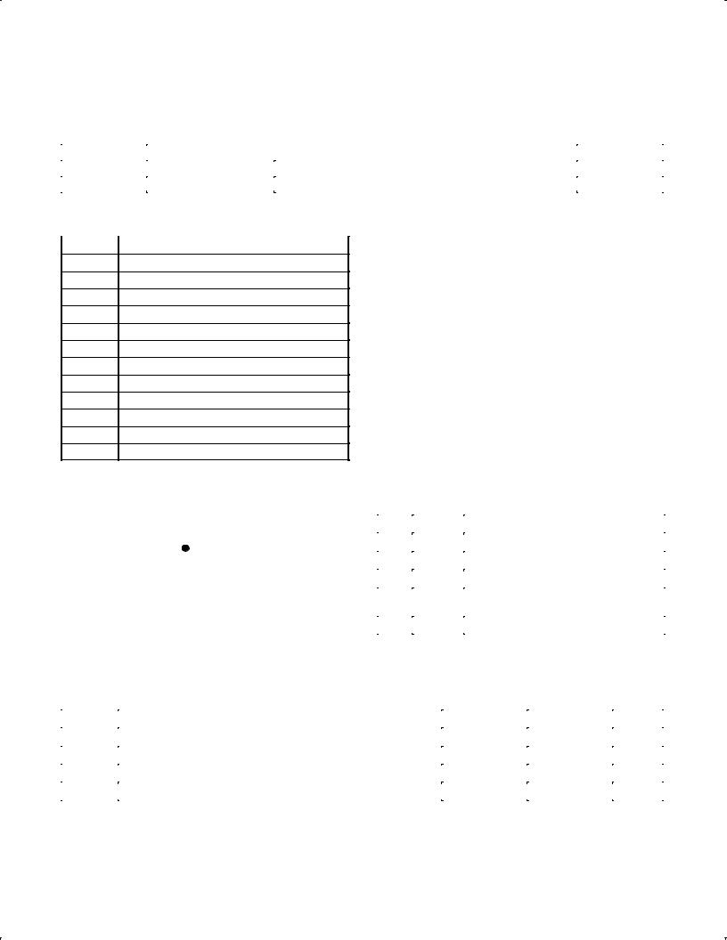
XX |
VOLTAGE (Typical) |
|
|
|
||
191.9 V
202.0 V
272.7 V
282.8 V
292.9 V
303.0 V
313.1 V
424.2 V
434.3 V
444.4 V
454.5 V
464.6 V
PIN CONFIGURATION |
|
|
|
|
PIN DESCRIPTION |
|
|
|
|
|||||||
|
|
|
|
|
|
|
|
PIN |
SYMBOL |
|
|
DESCRIPTION |
|
|
||
|
|
|
|
|
|
|
|
1 |
NC |
No connection. |
|
|
||||
|
NC |
1 |
|
|
5 |
VCC |
|
|
|
|
|
|
|
|
|
|
|
|
|
|
|
|
|
|
2 |
SUB |
Substrate. Connect to ground (GND). |
||||||
|
|
|
|
NE56631-XX |
|
|
|
|
|
|
|
|
|
|
|
|
|
|
|
|
|
|
|
3 |
GND |
Ground. Negative supply. |
|
|
|||||
|
SUB |
2 |
|
|
|
|
|
|
||||||||
|
|
|
|
|
|
|
|
|
|
|
|
|
|
|
|
|
|
|
|
|
|
|
|
|
4 |
VOUT |
Reset output |
|
. |
|
|
||
|
|
|
|
|
|
|
|
(RESET) |
|
|
||||||
|
GND |
|
|
|
|
VOUT |
|
|
|
|
Active-LOW, open collector. |
|
|
|||
|
3 |
|
|
4 |
|
|
|
|
|
|
||||||
|
|
|
|
|
|
|
|
|
|
|
|
|
|
|
||
|
|
|
|
|
|
|
|
5 |
VCC |
Positive supply voltage |
|
|
||||
|
|
|
|
SL01737 |
|
|
||||||||||
|
|
|
|
|
|
|
|
|
|
|
|
|
|
|
||
|
|
|
|
|
|
|
|
|
|
|
|
|
||||
|
Figure 2. |
Pin configuration. |
|
|
|
|
|
|
|
|
||||||
MAXIMUM RATINGS |
|
|
|
|
|
|
|
|
|
|
|
|
|
|||
|
|
|
|
|
|
|
|
|
|
|
|
|
||||
SYMBOL |
|
|
|
|
PARAMETER |
|
|
MIN. |
|
MAX. |
UNIT |
|
||||
|
|
|
|
|
|
|
|
|
|
|
|
|||||
VCC |
Supply voltage |
|
|
|
|
|
±0.3 |
|
+10 |
V |
|
|||||
Tamb |
Ambient operating temperature |
|
|
|
|
|
±20 |
|
+75 |
°C |
|
|||||
Tstg |
Storage temperature |
|
|
|
|
|
±40 |
|
+125 |
°C |
|
|||||
PD |
Power dissipation |
|
|
|
|
|
± |
|
150 |
mW |
|
|||||
2003 Feb 14 |
3 |

Philips Semiconductors |
Product data |
|
|
|
|
Active-LOW system reset |
NE56631-XX |
|
|
|
|
ELECTRICAL CHARACTERISTICS
Tamb = 25 °C, unless otherwise specified.
SYMBOL |
PARAMETER |
CONDITIONS |
MIN. |
TYP. |
MAX. |
UNIT |
|
|
|
|
|
|
|
VS |
Detection threshold voltage |
RL = 470 Ω; VOL ≤ 0.4 V; |
0.97 VS |
VS |
1.03 VS |
V |
|
|
VCC = HIGH-to-LOW |
|
|
|
|
VS |
Hysteresis voltage |
RL = 470 Ω; |
30 |
50 |
100 |
mV |
|
|
VCC = LOW-to-HIGH-to-LOW |
|
|
|
|
VS/ T |
Detection threshold voltage |
RL = 470 Ω; Tamb = ±20 °C to +75 °C |
± |
±0.01 |
± |
%/°C |
|
temperature coefficient |
|
|
|
|
|
|
|
|
|
|
|
|
VOL |
LOW-level output voltage |
VCC = VS(min) ± 0.05 V; RL = 470 Ω |
± |
0.2 |
0.4 |
V |
ILO |
Output leakage current |
VCC = 10 V; VO = VCC |
± |
± |
±0.1 |
V |
ICCL |
Supply current (LOW Reset) |
VCC = VS(min) ± 0.05 V; RL = ∞ |
± |
1.0 |
2.0 |
μA |
ICCH |
Supply current (HIGH Reset) |
VCC = VS(typ) / 0.85 V; RL = ∞ |
± |
1.5 |
2.5 |
μA |
tPLH |
HIGH-to-LOW delay time |
CL = 100 pF; RL = 4.7 kΩ |
± |
20 |
60 |
μs |
tPHL |
LOW±to-HIGH delay time |
CL = 100 pF; RL = 4.7 kΩ |
± |
20 |
60 |
μs |
VOPL |
Minimum operating threshold voltage |
RL = 4.7 kΩ; VOL ≤ 0.4 V |
± |
0.65 |
0.80 |
V |
IOL1 |
Output current (LOW Reset) 1 |
VO = 0.4 V; RL = 0; |
± |
30 |
± |
mA |
|
|
VCC = VS(min) ± 0.05 V |
|
|
|
|
IOL2 |
Output current (LOW Reset) 2 |
VO = 0.4 V; RL = 0; |
± |
23 |
± |
mA |
|
|
VCC = VS(min) ± 0.15 V; |
|
|
|
|
|
|
Tamb = ±30 °C to +80 °C |
|
|
|
|
2003 Feb 14 |
4 |
 Loading...