


NE614AN
Philips Semiconductors
SA614A
Low power FM IF system
Product specification
Replaces data of December 15, 1994
1997 Nov 07
RF COMMUNICATIONS PRODUCTS
IC17 Data Handbook
Philips Semiconductors Product specification
SA614ALow power FM IF system
2
1997 Nov 07 853-0594 18663
DESCRIPTION
The SA614A is an improved monolithic low-power FM IF system
incorporating two limiting intermediate frequency amplifiers,
quadrature detector, muting, logarithmic received signal strength
indicator, and voltage regulator. The SA614A features higher IF
bandwidth (25MHz) and temperature compensated RSSI and
limiters permitting higher performance application compared with the
SA604. The SA614A is available in a 16-lead dual-in-line plastic
and 16-lead SO (surface-mounted miniature) package.
FEA TURES
•Low power consumption: 3.3mA typical
•Temperature compensated logarithmic Received Signal Strength
Indicator (RSSI) with a dynamic range in excess of 90dB
•Two audio outputs - muted and unmuted
•Low external component count; suitable for crystal/ceramic filters
•Excellent sensitivity: 1.5µV across input pins (0.22µV into 50Ω
matching network) for 12dB SINAD (Signal to Noise and Distortion
ratio) at 455kHz
•SA614A meets cellular radio specifications
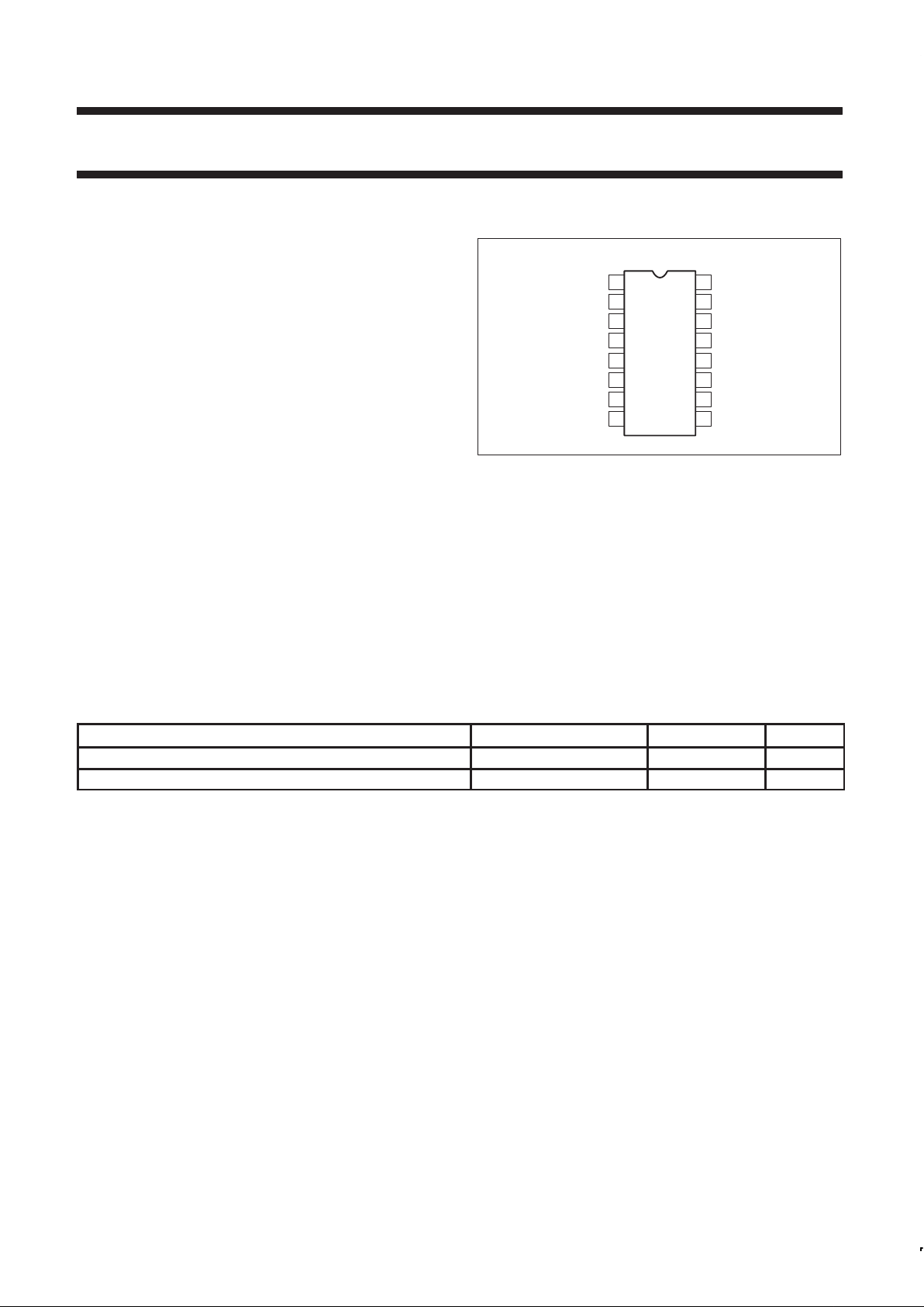
PIN CONFIGURATION
D and N Packages
IF AMP DECOUPLING
1
2
3
4
5
6
7
8
9
10
11
12
13
14
16
15
GND
MUTE INPUT
RSSI OUTPUT
MUTE AUDIO OUTPUT
UNMUTE AUDIO OUTPUT
QUADRATURE INPUT
IF AMP INPUT
IF AMP DECOUPLING
IF AMP OUTPUT
GND
LIMITER INPUT
LIMITER DECOUPLING
LIMITER DECOUPLING
LIMITER
V
CC
SR00323
Figure 1. Pin Configuration
APPLICATIONS
•Cellular radio FM IF
•High performance communications receivers
•Intermediate frequency amplification and detection up to 25MHz
•RF level meter
•Spectrum analyzer
•Instrumentation
•FSK and ASK data receivers
ORDERING INFORMATION
DESCRIPTION TEMPERATURE RANGE ORDER CODE DWG #
16-Pin Plastic Dual In-Line Package (DIP) -40 to +85°C SA614AN SOT38-4
16-Pin Plastic Small Outline (SO) package (Surface-mount) -40 to +85°C SA614AD SOT109-1

Philips Semiconductors Product specification
SA614ALow power FM IF system
1997 Nov 07
3
BLOCK DIAGRAM
16 15 14 13 12 11 10 9
87654321
SIGNAL
VOLTAGE
IF
AMP
LIMITER
REGULATOR
STRENGTH
GND
V
CC
GND
MUTE
QUAD
DET
LIMITER
SR00324
Figure 2. Block Diagram
ABSOLUTE MAXIMUM RATINGS
SYMBOL PARAMETER RATING UNITS
V
CC
Single supply voltage 9 V
T
STG
Storage temperature range -65 to +150
°C
T
A
Operating ambient temperature range SA614A -40 to +85
°C
θ
JA
Thermal impedance D package
N package
90
75
°C/W
°C/W
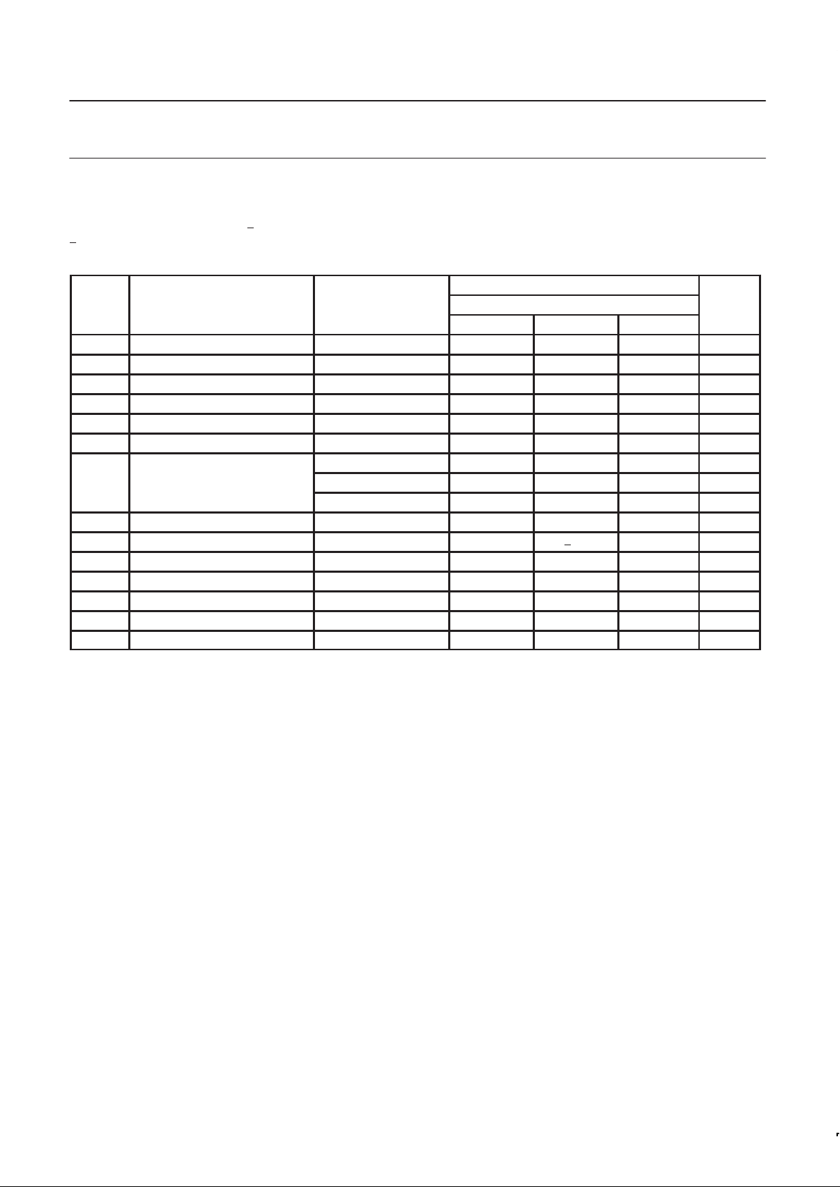
DC ELECTRICAL CHARACTERISTICS
VCC = +6V, TA = 25°C; unless otherwise stated.
LIMITS
SYMBOL PARAMETER TEST CONDITIONS SA614A UNITS
MIN TYP MAX
V
CC
Power supply voltage range 4.5 8.0 V
I
CC
DC current drain 2.5 3.3 4.0 mA
Mute switch input threshold (ON)
(OFF)
1.7
1.0
V
V
Philips Semiconductors Product specification
SA614ALow power FM IF system
1997 Nov 07
4
AC ELECTRICAL CHARACTERISTICS
Typical reading at TA = 25°C; VCC = +6V , unless otherwise stated. IF frequency = 455kHz; IF level = -47dBm; FM modulation = 1kHz with
+
8kHz peak deviation. Audio output with C-message weighted filter and de-emphasis capacitor. Test circuit Figure 3. The parameters listed
below are tested using automatic test equipment to assure consistent electrical characterristics. The limits do not represent the ultimate
performance limits of the device. Use of an optimized RF layout will improve many of the listed parameters.
LIMITS
SYMBOL PARAMETER TEST CONDITIONS SA614A UNITS
MIN TYP MAX
Input limiting -3dB Test at Pin 16 -92 dBm/50Ω
AM rejection 80% AM 1kHz 25 33 dB
Recovered audio level 15nF de-emphasis 60 175 260 mV
RMS
Recovered audio level 150pF de-emphasis 530 mV
RMS
THD Total harmonic distortion -30 -42 dB
S/N Signal-to-noise ratio No modulation for noise 68 dB
RF level = -118dBm 0 160 800 mV
RSSI output
1
RF level = -68dBm 1.7 2.50 3.3 V
RF level = -18dBm 3.6 4.80 5.8 V
RSSI range R4 = 100k (Pin 5) 80 dB
RSSI accuracy R4 = 100k (Pin 5) +2.0 dB
IF input impedance 1.4 1.6 kΩ
IF output impedance 0.85 1.0 kΩ
Limiter input impedance 1.4 1.6 kΩ
Unmuted audio output resistance 58 kΩ
Muted audio output resistance 58 kΩ
NOTE:
1. SA614A data sheets refer to power at 50Ω input termination; about 21dB less power actually enters the internal 1.5k input.
SA614A (50) SA614A (1.5k)/SA615 (1.5k)
-97dBm -118dBm
-47dBm -68dBm
+3dBm -18dBm
The SA615 and SA614A are both derived from the same basic die. The SA615 performance plots are directly applicable to the SA614A.
Philips Semiconductors Product specification
SA614ALow power FM IF system
1997 Nov 07
5
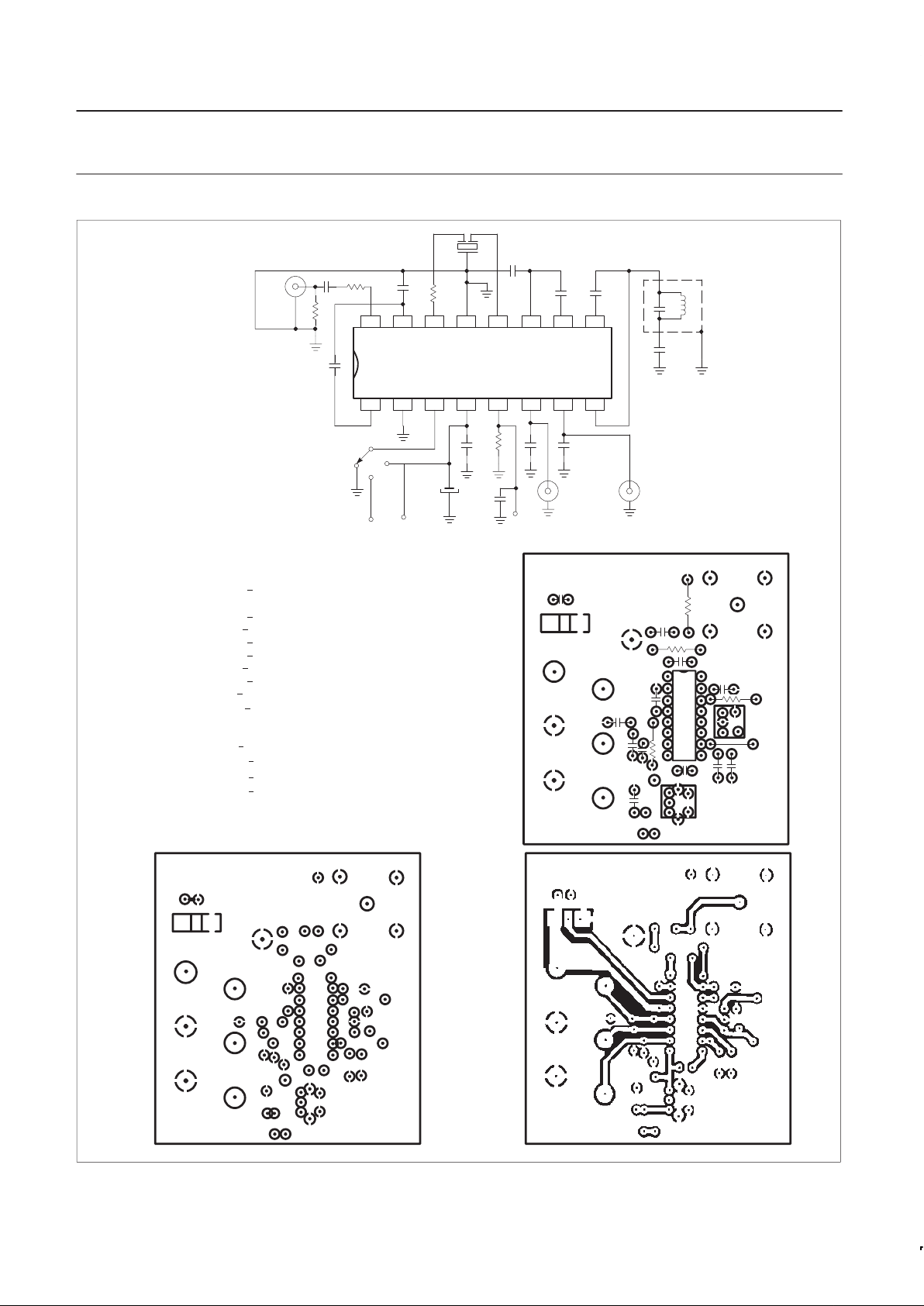
IF INPUT
GND
RSSI AUDIO DATA
GND
GND
OFF
ON
V
CC
SIGNETICS
NE614 TEST CKT
M
U
T
E
100nF + 80 – 20% 63V K10000–25V Ceramic
455kHz Ceramic Filter Murata SFG455A3
100nF +
10% 50V
100nF +
10% 50V
455kHz (Ce = 180pF) TOKO RMC 2A6597H
51Ω +
1% 1/4W Metal Film
150pF +
2% 100V N1500 Ceramic
6.8µF +
20% 25V Tantalum
1nF +
10% 100V K2000-Y5P Ceramic
15nF +
10% 50V
100nF +
10% 50V
C1
C2
C3
C4
C5
C6
C7
C8
C9
C10
C11
C12
F1
F2
R1
100nF +10% 50V
100nF +
10% 50V
100nF +10% 50V
10pF +
2% 100V NPO Ceramic
R2
R3
R4
1500Ω +
1% 1/4W Metal Film
1500Ω +
5% 1/8W Carbon Composition
100kΩ +
1% 1/4W Metal Film
16 15 14 13 12 11 10 9
87654321
NE614A TEST CIRCUIT
SA614A
INPUT
Q = 20 LOADED
MUTE
INPUT
RSSI
OUTPUT
AUDIO
OUTPUT
DATA
OUTPUT
C
5
C
3
C
6
S
1
C
10
C
8
F
2
C
12
C
9
F
1
C
7
C
11
R
1
R
2
R
3
C
4
C
1
C
2
R
4
IF INPUT
GND
RSSI AUDIO DATA
GND
GND
OFF
ON
V
CC
SIGNETICS
NE614 TEST CKT
M
U
T
E
SR00325
Figure 3. SA614A Test Circuit
 Loading...