


Net 1Card IB 2/15/00 12:17 PM Page 1
Professional Color Television
NET1CARD
®
T E L E V I S I O N
OWNER’S
MANUAL
AND
SET-UP GUIDE
 IndustryStandards™
Net 1Card IB 2/15/00 12:17 PM Page 2
KNOW THESE SAFETY SYMBOLS
t |
CAUTION |
s |
RISK OF ELECTRIC SHOCK |
||
|
DO NOT OPEN |
|
CAUTION: TO REDUCE THE RISK OF ELECTRIC SHOCK, DO NOT
REMOVE COVER (OR BACK). NO USER-SERVICEABLE PARTS
INSIDE. REFER SERVICING TO QUALIFIED SERVICE PERSONNEL.
t This “bolt of lightning” indicates uninsulated material within your unit which may cause an electrical shock. For the safety of everyone in your household, please do not remove product covering.
s The “exclamation point” calls attention to features for which you should read the enclosed literature closely to prevent operating and maintenance problems.
WARNING: TO PREVENT FIRE OR SHOCK HAZARD, DO NOT EXPOSE THIS EQUIPMENT TO RAIN OR MOISTURE.
CAUTION: To prevent electric shock, match wide blade of plug to wide slot, and fully insert.
ATTENTION: Pour éviter les chocs électrques, introduire la lame la plus large de la fiche dams la borne correspondante de la prise et pousser jussssqu'au fond.
For Customer Use:
Enter below the Serial No. which is located on the product. Retain this information for future reference.
Model No
Serial No.
Net 1CardTM, SmartCardTMTelevision, SmartLinkTM Connector and SmartPlugTM Series are all registered trademarks of the Philips Consumer Electronics Company.
2
TABLE OF CONTENTS
Getting Started


 Warning/Precautions . . . . . . . . . . . . . . . . . . .2
 Introduction . . . . . . . . . . . . . . . . . . . . . . . . .4 Features . . . . . . . . . . . . . . . . . . . . . . . . . . . .4 Basic Remote Control Operations . . . . . . . . . . . . . . . .5
Unpacking and Installation . . . . . . . . . . . . . . . . . . .6-9 Input/Output Jacks . . . . . . . . . . . . . . . . . . . . . . . . . . .9
Hooking up the Net 1Card Television
Antenna TV Connections . . . . . . . . . . . .10-11
Cable TV Connections . . . . . . . . . . . . . .12-13 ideo Input Connections . . . . . . . . . . . . . .14-15 Input Connections . . . . . . . . . . . . . . . . .16-17
On-Screen Menu Options
Commercial Settings . . . . . . . . . . . . . . . . . .18 |
|||
• Commercial / Consumer Mode . . . . . . . .18 |
|||
• Receiver / Transmitter / Factory . . . . . . . . . . . . .19 |
|||
• Front Keypad / Cable / Exit |
. . . . . . . . . . . . . . . .20 |
||
Receiver Control |
. . . . . . . . . . . . . . . . . . . . . . . . . . .21 |
||
• Receiver Group IDs . . . . . . . . . . . . . . . . . . . . . .21 |
|||
• Receiver Set IDs / Exit . . . . . . . . . . . . . . . . . . . .22 |
|||
Transmitter Control |
. . . . . . . . . . . . . . . . . . . . . . . . .23 |
||
• Address Type / Group IDs . . . . . . . . . . . . . . . . . .23 |
|||
• Receiver Power . . . . . . . . . . . . . . . . . . . . . . . . . .24 |
|||
• Receiver Volume . . . . . . . . . . . . . . . . . . . . . . . . .25 |
|||
• Receiver Channel . . . . . . . . . . . . . . . . . . . . . . . .26 |
|||
• Receiver Lockout / Update Receiver TVs / Exit .27 |
|||
• Receiver Reset |
|
. . . . . . . . . . . . . . . . . . . . . . . . . .29 |
|
Factory Test Menu |
|
. . . . . . . . . . . . . . . . . . . . . . . . . .30 |
|
Television Features |
. . . . . . . . . . . . . . . . . . . . . . . . . .31 |
||
Closed Captioning |
|
. . . . . . . . . . . . . . . . . . . . . . . . . .36 |
|
General Information
Index . . . . . . . . . . . . . . . . . . . . . . . . . . . . .37
Glossary . . . . . . . . . . . . . . . . . . . . . . . . . . .38
Troubleshooting . . . . . . . . . . . . . . . . . . . . .39
Warranty . . . . . . . . . . . . . . . . . . . . . . . . . . . . . . . . . .40
3
Net 1Card IB 2/15/00 12:17 PM Page 4
INTRODUCTION
The Net1Card is a network television systems control SmartCard that is designed to work with Philips SmartCard televisions in a balanced RF distribution system. The Net1Card allows an individual with a unit set in the Transmitting mode to control all televisions, up to 8 zones of televisions, or a single television, all set in the Receive mode. The controls include turning the sets on, setting the volume, and tuning to a specific channel for live or prerecorded messages or programs. Any Net1Card can be set up to transmit or receive.
The Net1Card allows the individual with the Transmitter unit the option to lock out the Receiver units so that the power, volume, or channels cannot be changed until they are restored by the Transmitter unit. All of this is done in a matter of seconds by using an optional T374AH IR remote control device. (See page 5.) Other features include the ability to change channels for different messages, turn off all receiver televisions from a single location, send different messages or programs to different groups or individual sets. The Net1Card is easy to install, set up, and operate. The Net1Card also has the ability to poll an individual television to ensure correct systems operation.
The Net1Card also has composite video input, an S- Video input, two audio inputs, an RF input, a speaker jack and a cloning port for easy connectivity to a variety of media devices.
FEATURES
•Audio/Video Jacks for direct connections with VCRs (or other video accessories) for quality TV picture and sound playback.
•Audio/Video Inputs.
•Audio/S-Video Inputs.
•Ability to broadcast to an individual TV, to a group of TVs, or to all the TVs in the series.
•Ability to poll individual TVs.
•Clone port for limited applications.
4
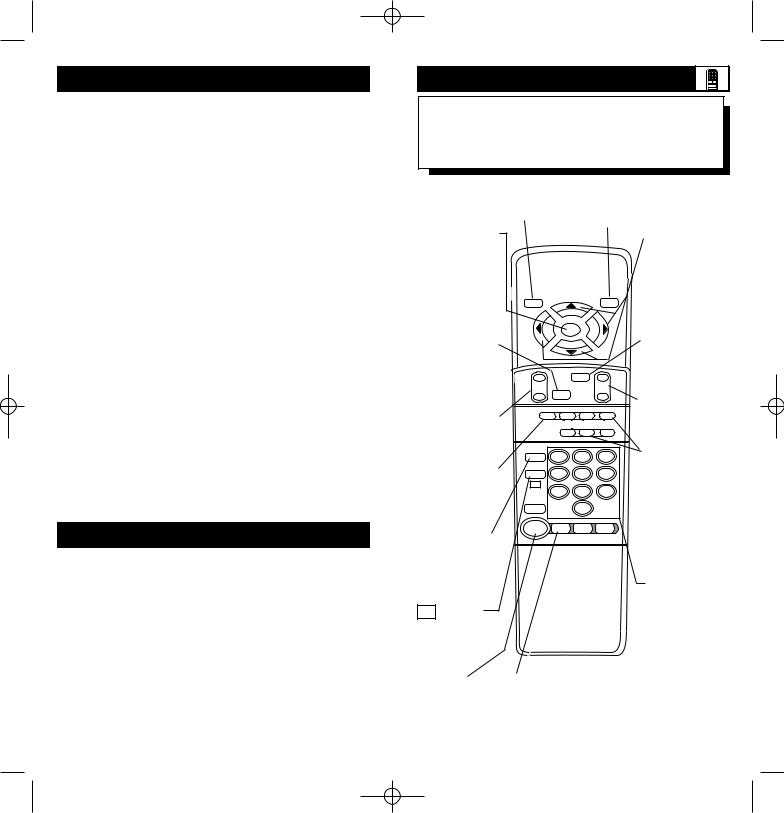
REMOTE OPERATION
Listed below is a brief description of the TH374AH remote control. You need one remote control
(sold separately) to setup and operate the Net 1Card.
Only buttons important to Net1Card are described.
SLEEP - In the Consumer mode, press |
RECALL - Press this button to |
this button to select the amount of time |
bring up the closed caption |
you want before the TV turns off. |
mode or to exit Net1Card |
|
menus. |
SELECT (M) - In the Consumer mode, press this button to bring up the on-screen menu options. Also may be used to advance the cursor.
MUTE - Press this button to turn the sound OFF on the TV. Press again to return the sound to its previous level.
VOL(ume) - Press this button to adjust the sound level of the TV.
A - Press the A button to set a TV in the Net1Card Transmit, Receive, or Factory mode.
ENTER/RESET -
In the Consumer mode, press this button to reset TV settings to factory.
CC - Press this button to bring the Closed Captioning option to the screen.
SLEEP |
|
|
RECALL |
- |
SELECT |
|
+ |
M |
|
||
|
A/CH |
|
|
VOL |
MUTE |
|
CH |
|
|
|
|
A |
B |
C |
D |
|
E |
F |
G |
ENTER |
1 |
2 |
3 |
P.PREF |
|||
|
4 |
5 |
6 |
CC |
7 |
8 |
9 |
|
|||
CH GDE |
|
0 |
|
POWER |
TV |
TV |
DCM |
|
GUEST |
SETUP |
SETUP |
POWER - |
TV/GUEST - Press this button before |
Press this |
trying to setup the TV after installing |
button to |
the Net1Card. If the menus do not |
turn the TV |
come up when you press the A or D |
ON or OFF. |
button, press this button and try again. |
|
5 |
CURSOR KEYS -
Press these buttons (▲ ▼ © ß ) to scroll or move through the onscreen menu or to adjust the picture in certain features.
A/CH - Press this button to toggle between the present and last viewed channels.
CH(annel) - Press this button to scroll through all available channels.
D & F - Press the the D button to select features under each specific Net1Card mode. Press the F button to display the version of Net 1Card installed.
NUMBERED BUTTONS - Press these buttons to directly access any available channel. (If a single digit channel is chosen, press 0 first. Example for channel 6; first press 0, then 6.) In certain Net1Card menus, use these buttons to make selections.

Net 1Card IB 2/15/00 12:17 PM Page 6
NET1CARD ASSEMBLY
hen unpacking the Net1Card components from the box, be careful pulling the items
. The box is packed with three separately packaged items: the Net1Card Assembly Cover,
Net1Card Circuit and Panel Board, and the
Input Cable. Unfold the cardboard holders remove the circuit board. Use the following uctions to begin assembling the unit.
BEGIN
 First, unplug the AC power cord from the outlet. Next, on the back of the TV,
remove the hex head retaining nut from around RF IN (antenna) jack.
 Remove the hex head screws holding the Monitor Card cover in place. Now, slide the jack panel cover off. Be careful when pulling the cover off. Make sure the RF IN jack slides out of the cover, but remains attached to the TV.
SMART HELP


 Remember to make sure you have the sup-
  plied Net1Card parts before unplugging the TV.
You will need a hex head screw driver and a hex head wrench in order to do the disassembly on the back of the TV.
Keep the hex head nut from the back of the TV.
6
Unpacking
RF Input Cable
(In Poly Bag)
Rear Cover in
Bubble Pack Bag
Net1Card Circuit and Panel Board
(Packed in folded cardboard and plastic)
Cardboard Box
Removing
Monitor
Cover
Back of TV
Monitor Cover
1 |
RF Input Plug |
Retaining Nut |
|
|
RF IN |
Hex head screw
2 2
7

Net 1Card IB 2/15/00 12:17 PM Page 8
NET1CARD ASSEMBLY
Installation of Net1Card is easy. Remember to follow these instructions, be patient, and use the T374AH Set Up Remote Control (see T374AH Remote Control Instructions - part #
IB7166E002 for complete details).
BEGIN
 Disconnect the cable from the RF IN (antenna) jack inside the TV. Then, connect the cable onto the yellow plug farthest from the 32-pin connector at the rear of the Circuit and Panel Board.
 Connect the RF cable (included) onto the yellow plug closest to the 32-pin connector on the Circuit and Panel Board. Then, connect the other end of the cable to RF IN jack inside the TV.
 Now, insert the Net1Card (with its components facing down) into the back of the TV. Line up and guide the 32-pin connector. Note: there are guide pins to help properly insert the card. Gently, but firmly, press the card into place.
IN jack through the Assembly Cover and secure
place with the hex head retaining nut. Once attach the Cover to the back of the TV using
hex head screws.
SMART HELP


 Be sure to align the 32 pin connector before
  pressing into place. Never force the Net1Card into
the connector. If it will not go in smoothly, realign the guide pins and try again. Do not use the Net1Card jacks to push the card assembly into place. Push on the cover directly behind the card itself.
If your RF IN cable will not disconnect from the Monitor Cover, call (800) 851-8885 to order a replacement cable.
8
Rear of Smart Card
Television
Hex Head Screws
2
3
32 Pin Connector
Guide Pin
Component
Side Down
2
1
Component
Side Up
CLONE
PORT
VIDEO AUDIO VIDEO AUDIO
1 |
RF IN |
Net1Card |
|
|
|||
4 |
|
|
|
|
|
Net1Card and |
|
|
RF IN (Antenna Jack) |
Cover Assembly |
|
|
|
||
Speaker Jack - For con- |
Clone Port - 6 Pin |
AUDIO / VIDEO Inputs. For |
|
Connector for limited |
connection to video / audio |
||
necting external speakers. |
|||
applications. |
equipment with phono jacks. |
||
|
|
CLONE |
|
|
|
|
PORT |
S-VIDEO S-AUDIO |
VIDEO |
AUDIO |
|
|
|||
|
RF IN |
|
|
|
RF IN - |
|
S-VIDEO / S-AUDIO Input. For con- |
||
Antenna/Cable |
|
nection to video / audio equipment with |
||
75Ω Input |
|
S-Video / S-Audio out jacks |
|
|
|
|
9 |
|
|

Net 1Card IB 2/15/00 12:17 PM Page 10
ANTENNA HOOKUPS
Acombination antenna receives normal broadcast channels (VHF 2-13 and UHF
14-69). Your connection is easy since there is only one 75Ω (ohm) antenna plug on the back of your TV - and that’s where the antenna goes. (If you have more than one antenna, please refer to the diagram at the bottom of page 11 for additional hookups.)
BEGIN
has a round cable (75 ohm) ready to connect it to the
.
your antenna has flat twin-lead wire (300 you first need to attach the antenna wires to
screws on a 300 to 75 ohm adapter.
end of the adapter (or antenplug on the rear of the TV. If
round end of the antenna wire is threaded, it down tight.
SMART HELP


 Remember, be sure to set the TV for the
  type signal you’ve connected.
To set the TV to select only the channel numbers in your area see how to “Program” or “Add” channels in memory.
To order any optional accessory contact your dealer or call the toll-free accessory ordering number
(1-800-292-6066):
•UHF/VHF Combiner: (SBV1133AO1)
•75-300 Ohm Adapter: (SBV1113AO1)
•300-75 Ohm Adapter: (483521827003)
10
Combination VHF/UHF
Antenna (Outdoor or Indoor)
1 |
300 to 75Ω |
Adapter |
|
(483521827003) |
|
Twin Lead |
|
Wire |
|
Back of TV
CLONE |
2 |
|
|
|
P |
IO |
VIDEO |
AUDIO |
|
|
||||
IN |
|
|
|
|
Round Cable |
Net1Card |
|
Jack Panel |
||
75Ω |
OPTIONAL HOOKUPS
Back of TV
Outdoor UHF Antenna
(Twin Lead 300 Ohm)
Outdoor VHF
Antenna
(Twin Lead
300 Ohm)
Twin Lead
Wire
Round End
UHF 
 300Ω
300Ω
 VHFVVHF
Outdoor VHF |
|
|
Antenna |
|
|
(Round 75Ω |
OR |
ADAPTER |
Cable) |
|
|
|
|
|
|
Ω |
|
-300 |
75-300 Ohm Adapter |
75 |
FO |
|
|
|
|
|
|
CUS |
|
|
|
|
|
|
|
DCLONE |
|
S-VIDEO |
S-AUDIO |
VIDEO |
AUDIO |
|
NCPORT |
|
||||
|
E |
ScanCard |
II |
|
|
|
ENHA |
|
|
|
|
||
RF IN |
|
|
|
|
|
|
Net1Card
Jack Panel
UHF/VHF Combiner
Round Cable 75Ω
11

Net 1Card IB 2/15/00 12:17 PM Page 12
CABLE TV HOOKUP
Your Cable TV input into your home may be a single (75 ohm) cable, or a Converter
Box installation. In either case the connection to the TV is very easy. Just put the threaded end of the cable signal to the TV's antenna plug and screw it down tight.
BEGIN
is a single round ready to connect to the
.
you have a Cable TV Converter Box:
the Cable TV signal to the Cable Signal plug on the Converter.
cable to the RF IN plug
have a Cable TV Converter Box:
the OUT(put) plug from the Converter to RF IN plug on the TV (connecting cable sup-
with the Converter).
SMART HELP


 Remember, set the TV to the “Cable TV
  Mode.” Then, to select only the channel
numbers on your Cable system see “Auto Program” (refer to page 34 for both features).
If you use a Cable Converter box, set the TV to the same channel as the converter's CH 3/4 switch (on the rear of the converter.)
12
Back of TV
Cable TV Company
Round Cable
75Ω Ohm
OUT
CLONE |
2 |
|
|
|
P |
IO |
VIDEO |
AUDIO |
|
|
||||
IN |
|
|
|
|
Net1Card
Cable TV Converter Box |
|
1 |
Jack Panel |
Connection |
|
|
|
|
|
|
|
OPTIONAL VCR HOOKUP |
|||
Outdoor VHF/UHF |
300 to 75Ω Ohm |
1 |
|
Adapter |
|
||
Antenna |
|
||
|
|
||
|
|
|
Round Cable |
|
|
|
75Ω Supplied |
|
OR |
|
with VCR |
|
|
|
|
|
IN FROM ANT. |
OUT TO TV |
|
Cable TV signal |
|
|
|
|
|
VCR |
|
|
|
CLONE |
|
|
|
PORT |
AUDIO |
|
|
|
|
|
|
RF IN |
|
|
|
Net1Card |
2 |
Back of TV |
Jack Panel |
||
|
|
||
|
|
|
|
13
 Loading...