


Order No: PAPAMY1601004CE
Installation Manual
|
|
|
|
|
|
Air Conditioner |
|
|
|
|
|
Indoor Unit |
Outdoor Unit |
|
|
|
|
|
CS-XE9SKUA |
CU-XE9SKUA |
|
|
|
|
|
CS-XE12SKUA |
CU-XE12SKUA |
|
|
|
|
|
|
Destination |
|
|
|
|
|
|
|
|
|
|
|
|
|
|
|
|
|
|
|
|
U.S.A. |
|
|
|
|
|
|
Canada |
|
|
|
|
|
|
|
|
|
|
|
|
|
|
|
|
|
|
|
|
|
CANCEL
 WARNING
This service information is designed for experienced repair technicians only and is not designed for use by the general public.
It does not contain warnings or cautions to advise non-technical individuals of potential dangers in attempting to service a product. Products powered by electricity should be serviced or repaired only by experienced professional technicians. Any attempt to service or repair the products dealt with in this service information by anyone else could result in serious injury or death.
IMPORTANT SAFETY NOTICE
There are special components used in this equipment which are important for safety. These parts are marked by ! in the Schematic Diagrams, Circuit Board Diagrams, Exploded Views and Replacement Parts List. It is essential that these critical parts should be replaced with manufacturer’s specified parts to prevent shock, fire or other hazards. Do not modify the original design without permission of manufacturer.
 PRECAUTION OF LOW TEMPERATURE
In order to avoid frostbite, be assured of no refrigerant leakage during the installation or repairing of refrigerant circuit.
© Panasonic Corporation 2016.
11. Installation Instruction
11.1 Select the Best Location
11.1.1Indoor Unit
Do not install the unit in excessive oil fume area such as kitchen, workshop and etc.
There should not be any heat source or steam near the unit.
There should not be any obstacles blocking the air circulation.
A place where air circulation in the room is good.
A place where drainage can be easily done.
A place where noise prevention is taken into consideration.
Do not install the unit near the door way.
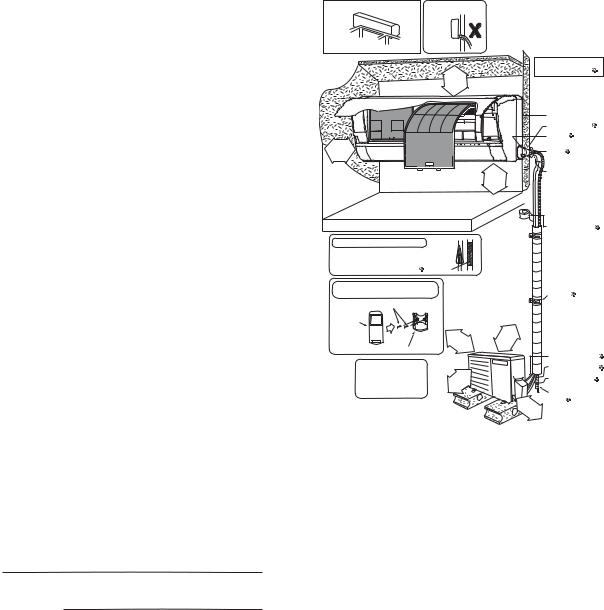
Ensure the spaces indicated by arrows from the wall, ceiling, fence or other obstacles.
Mount with the lowest moving parts at least 8ft (2.4 m) above floor or grade level.
11.1.2Outdoor Unit
If an awning is built over the unit to prevent direct sunlight or rain, be careful that heat radiation from the condenser is not obstructed.
There should not be any animal or plant which could be affected by hot air discharged.
Keep the spaces indicated by arrows from wall, ceiling, fence or other obstacles.
Do not place any obstacles which may cause a short circuit of the discharged air.
If piping length is over the [piping length for additional gas], additional refrigerant should be added as shown in the table.
Recommended installation height for outdoor unit should be above the seasonal snow level.
Be careful not to locate outdoor unit directly under a roof line where falling snow or ice can cause damage or dripping water can increase ice accumulation and defrost cycles.
|
Capacity |
Piping size |
Std. |
Max. |
Min. |
Max. |
Additional |
Piping |
||
Model |
Piping |
Piping |
Length for |
|||||||
|
(Btu/h) |
Gas |
Liquid |
Length |
Elevation |
Length |
Length |
Refrigerant |
add. gas |
|
|
|
3/8" |
|
|
|
|
|
|
|
|
XE9SKUA |
8700 |
|
|
|
|
|
|
|
||
(9.52 mm) |
1/4" |
24.6 ft |
49.2 ft |
9.8 ft |
65.6 ft |
0.2 oz/ft |
24.6 ft |
|||
|
|
|||||||||
XE12SKUA |
11500 |
1/2" |
(6.35 mm) |
(7.5 m) |
(15 m) |
(3 m) |
(20 m) |
(20 g/m) |
(7.5 m) |
|
(12.7 mm) |
|
|
|
|
|
|
|
|||
|
|
|
|
|
|
|
|
|
||
Example: For XE9SKUA
If the unit is installed at 32.8 ft (10 m) distance, the quantity of additional refrigerant should be 1.64 oz (50 g) .... (32.8 - 24.6) ft x 0.2 oz/ft = 1.64 oz.
((10-7.5) m x 20 g/m = 50 g)
11.1.3Indoor/Outdoor Unit Installation Diagram
Piping direction |
|
Do not bend up |
|
|
|
(Front side) |
drain hose |
Right |
|
|
|
Rear |
|
|
|
Right |
Left |
Left |
|
bottom |
Left bottom |
|
|
Rear |
|
||
|
|
||
|
|
|
|
|
|
|
|
|
|
|
92"/16 |
)mm e 5 orm 6( ro |
|||
|
|
|
|
|
|
|
|
|
|||||||
|
|
|
|
|
|||||||||||
|
|
|
|
|
|
|
|
|
|
|
|
|
|
|
|
|
|
|
|
|
|
|
|
|
|
|
|
|
|
|
|
|
|
|
|
|
|
|
|
|
|
|
|
|
|
|
|
|
|
|
|
|
|
|
|
|
|
|
|
|
|
|
|
|
|
|
|
|
|
|
|
|
|
|
|
|
|
|
|
|
|
|
|
|
|
|
|
|
|
|
|
|
|
|
|
 1 31/32" (50 mm) or more
(Left and right are identical)
Floor / Grade level
Insulation of piping connections
•Carry out insulation after checking for gas leaks and
secure with vinyl tape. |
Vinyl tape |
Attaching the remote control holder to the wall
Remote control holder fixing screws 6
Rem ote control 3
|
( |
3 1 |
|
|
|
|
|
|
5 |
|
|
||
|
1 |
0 |
|
/ |
|
|
|
|
|
|
1 |
||
|
or |
0 |
m |
|
6" |
|
Remote control holder 5 |
|
mor m) |
||||
|
|
|
e |
|
||
It is advisable to avoid m ore |
|
|
|
|
|
|
than 2 blockage directions. |
|
|
" |
) |
||
|
|
|
||||
For better ventilation & |
|
/8 |
|
m |
||
|
3 |
|
|
|
||
multiple-outdoor installation, |
9 |
|
m |
re |
||
3 |
|
|
|
|
||
00 o |
||||||
please consult authorized |
0 |
m |
|
|||
1 |
|
|
||||
( |
r |
|
|
|
||
dealer/specialist. |
|
o |
|
|
|
|
|
|
|
|
|
|
|
•This illustration is for explanation purposes only.
The indoor unit will actually face a different way.
|
|
|
|
|
|
|
|
|
|
|
|
|
|
|
|
Installation parts you |
|
||
|
|
|
|
|
|
|
|
|
|
|
|
|
|
|
|
should purchase ( |
) |
|
|
|
|
|
|
|
|
|
|
|
|
|
|
|
|
|
|
Installation plate |
1 |
|
|
|
|
|
|
|
|
|
|
|
|
|
|
|
|
|
|
Bushing-Sleeve ( ) |
|
||
|
|
|
|
|
|
|
|
|
|
|
|
|
|
|
|
Sleeve ( |
) |
|
|
|
|
|
|
|
|
|
|
|
|
|
|
|
|
|
|
Putty ( |
) |
|
|
|
|
|
|
|
|
|
|
|
|
|
|
|
|
|
|
(Gum Type Sealer) |
|
||
) |
|
|
|
|
|
|
|
|
|
|
|
|
|
|
|
Bend the pipe as |
|
|
|
(2ft.4 m morore |
|
|
|
|
|
|
|
|
|
|
|
|
|
|
|
|
|||
|
|
|
|
|
|
|
|
|
|
|
|
|
|
as possible, but be |
|
||||
|
|
|
|
|
|
|
|
|
|
|
|
|
|
|
|
closely on the wall |
|
||
8 |
|
|
|
|
|
|
|
|
|
|
|
|
|
|
|
careful that it doesn’t |
|
||
|
|
|
|
|
|
|
|
|
|
|
|
|
|
|
|
|
|||
|
|
|
|
|
|
|
|
|
|
|
|
|
|
|
|
break. |
|
|
|
|
|
|
|
|
|
|
|
|
|
|
|
|
|
|
|
Vinyl tape (wide) ( ) |
|
||
|
|
|
|
|
|
|
|
|
|
|
|
|
|
|
|
• Apply after carrying |
|||
|
|
|
|
|
|
|
|
|
|
|
|
|
|
|
|
out a drainage test. |
|
||
|
|
|
|
|
|
|
|
|
|
|
|
|
|
|
|
• To carry out the |
|
||
|
|
|
|
|
|
|
|
|
|
|
|
|
|
|
|
drainage test, |
|
|
|
|
|
|
|
|
|
|
|
|
|
|
|
|
|
|
|
remove the air filters |
|||
|
|
|
|
|
|
|
|
|
|
|
|
|
|
|
|
and pour water into |
|
||
|
|
|
|
|
|
|
|
|
|
|
|
|
|
|
|
the heat exchanger. |
|||
|
|
|
|
|
|
|
|
|
|
|
|
|
|
|
|
Saddle ( ) |
|
|
|
|
|
|
|
/ 1 |
6 |
" |
|
m |
) |
|
|
|
|
|
|
|
|
|
|
|
|
5 |
|
|
m |
r e |
|
|
|
|
|
|
|
|
|
||||
|
1 |
|
|
|
|
|
|
|
|
|
|
|
|
|
|||||
3 |
|
0 |
0 |
|
m |
o |
|
|
|
|
|
|
|
|
|
||||
|
|
1 |
|
|
|
|
|
|
|
|
|
|
|
|
|||||
|
( |
|
o |
r |
|
|
|
|
|
|
|
|
|
|
|
||||
|
|
|
|
|
|
|
|
|
|
|
|
|
|
|
|
||||
|
|
|
|
|
|
|
|
|
|
|
|
|
|
|
|
|
|
|
|
|
|
|
|
|
|
|
|
|
|
|
|
|
|
|
|
Connection cable ( |
) |
||
|
|
|
|
|
|
|
|
|
|
|
|
|
|
|
|
Liquid side piping ( |
) |
||
|
|
|
|
|
|
|
|
|
|
|
|
|
|
|
|
Gas side piping ( ) |
|
||
|
|
|
|
|
|
|
|
|
|
|
1 |
|
|
|
Additional drain |
|
|
||
|
|
|
|
|
|
|
|
|
|
|
|
|
|
hose ( |
) |
|
|
||
|
|
|
|
|
|
|
|
|
|
( |
11 |
|
|
|
|||||
|
|
|
|
|
|
|
|
|
|
3 |
|
|
3 |
|
|
|
|
||
|
|
|
|
|
|
|
|
|
|
|
0 |
|
/ |
|
|
|
|
||
|
|
|
|
|
|
|
|
|
|
o |
|
0 |
|
1 |
|
|
|
||
|
|
|
|
|
|
|
|
|
|
|
|
m |
6 |
|
|
|
|||
|
|
|
|
|
|
|
|
|
|
r |
|
|
" |
|
|
|
|||
|
|
|
|
|
|
|
|
|
|
|
m |
|
|
|
|
|
|
|
|
|
|
|
|
|
|
|
|
|
|
|
|
o m |
|
|
|
|
|||
|
|
|
|
|
|
|
|
|
|
|
|
|
r |
|
) |
|
|
|
|
|
|
|
|
|
|
|
|
|
|
|
|
|
e |
|
|
|
|
|
|
24
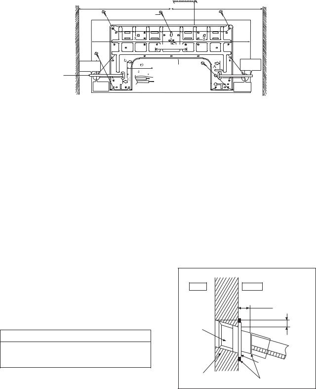
11.2 Indoor Unit
The mounting wall shall be strong and solid enough to prevent it from vibration.
|
Wall |
Wall |
Wall |
More than 1 |
More than 1 |
|
|
2 screw |
More |
|
|
|
than 2 |
|
|
|
|
|
|
|
|
|
|
5 1/16" (128 mm) |
|
|
|
|
|
DISTANCE TO |
|
|
|
|
PIPE HOLE |
|
|
|
|
CENTER 128 mm |
9 17/32" |
|
|
|
9 17/32" |
|
|
Installation |
(241.5 mm) |
|
(241.5 mm) |
|
|
||
|
|
|
||
Measuring |
PIPEHOLECENTER |
|
plate 1 |
|
Tape |
|
|
|
|
|
|
|
|
|
|
DISTANCE |
|
|
PIPE HOLE |
|
TO PIPE |
|
|
CENTER |
5 1/16" |
HOLE |
|
|
5 1/16" |
CENTER |
|
|
||
128 mm |
|
|
||
(128 mm) |
|
|
|
(128 mm) |
Model |
|
|
Dimension |
|
|
||
1 |
2 |
3 |
4 |
5 |
6 |
||
|
|||||||
|
|
|
|
|
|
|
|
XE9SKUA, XE12SKUA |
19-9/32" |
3-7/32" |
17-9/32" |
17" |
1-11/16" |
3-3/4" |
|
(490 mm) |
(82 mm) |
(439 mm) |
(432 mm) |
(43 mm) |
(95 mm) |
||
|
|||||||
The center of installation plate should be at more than 1 at right and left of the wall.
The distance from installation plate edge to ceiling should more than 2.
From installation plate left edge to unit’s left side is 3.
From installation plate right edge to unit’s right is 4.
B: For left side piping, piping connection for liquid should be about 5 from this line. : For left side piping, piping connection for gas should be about 6 from this line.
1Mount the installation plate on the wall with 5 screws or more (at least 5 screws). (If mounting the unit on the concrete wall, consider using anchor bolts.)
o Always mount the installation plate horizontally by aligning the marking-off line with the thread and using a level gauge.
2Drill the piping plate hole with ø2-3/4" (ø70 mm) hole-core drill.
o Line according to the left and right side of the installation plate. The meeting point of the extended line is the center of the hole. Another method is by putting measuring tape at position as shown in the diagram above. The hole center is obtained by measuring the distance namely 5-1/16" (128 mm) for left and right hole respectively.
o Drill the piping hole at either the right or the left and the hole should be slightly slanting to the outdoor side.
11.2.1To Drill a Hole in the Wall and Install a Sleeve of Piping
1Insert the piping sleeve to the hole.
2Fix the bushing to the sleeve.
3Cut the sleeve until it extrudes about 19/32" (15 mm) from the wall.
 CAUTION
 When the wall is hollow, please be sure to use the sleeve for tube assembly to prevent dangers caused by mice biting the connection cable.
4Finish by sealing the sleeve with putty or caulking compound at the final stage.
|
Wall |
Indoor |
Outdoor |
|
19/32" (15 mm) |
Sleeve |
|
for tube |
|
assembly |
|
|
Approx. 7/32" - 9/32" |
|
(5-7 mm) |
|
Bushing for tube |
|
assembly |
ø2 3/4" (ø70 mm) |
Putty or caulking compound |
through hole |
25
 Loading...