


 Loading...
TECHNICAL & SERVICE MANUAL
CS-KS12NB41 & CZ-18BT1U + CU-KS12NK1A CS-KS18NB4UW & CZ-18BT1U + CU-KS18NKU CS-KS18NB4UW & CZ-18BT1U + CU-KS18NKUA
DC INVERTER SPLIT SYSTEM AIR CONDITIONER
Indoor Model No. |
Product Code No. |
Body (Panel) |
Body (Panel) |
|
|
CS-KS12NB41 (CZ-18BT1U) |
1 852 361 04 (1 852 361 15) |
|
|
CS-KS18NB4UW (CZ-18BT1U) |
1 852 361 06 (1 852 361 15) |
|
|
Outdoor Model No. Product Code No.
CU-KS18NKU |
1 852 361 18 |
CU-KS12NK1A |
1 852 361 16 |
CU-KS18NKUA |
1 852 361 19 |
Indoor Unit |
|
Outdoor Unit |
|
|
|
Body
Panel |
|
CS-KS12NB41 (Body) & CZ-18BT1U (Panel) |
|
CS-KS18NB4UW (Body) & CZ-18BT1U (Panel) |
CU-KS12NK1A |
Remote Controller
CU-KS18NKU
Wired Remote Controller 


 CU-KS18NKUA
(Option)
REFERENCE NO. SM700879
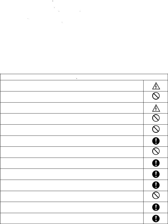
 SAFETY PRECAUTIONS
•Before doing repair work, please read the " SAFETY PRECAUTIONS" carefully and fully understand them.
•The precautionary items here are divided into " Warning" and "
 Caution" items.
Items in particular which may cause death or serious injury to the service personnel if the work is not performed correctly,
are included in the " Warning" table.
However, even precautionary items identified as " Caution" also have the potential for serious consequences if not performed correctly.
Important safety precautions are described for all items in both categories. Be sure to carefully follow all of them.
•Symbol Indication
 : This symbol indicates items to which we need to pay attention. In this triangle, a definite precautionary item is described.
 : This symbol indicates the item to be prohibited.
In or close to this circle, a prohibited item is described.
 : This symbol indicates the items requiring special attention or instruction. In or close to this circle, a prohibited item is described.
•After doing repair work, perform a test run to confirm that there are no abnormalities. At the same time, explain the precautions in use to the user.
 Warning
Before performing an overhaul, disconnect the power plug or power cable from the unit.
Performing the work with the power supplied to the unit, may cause an electric shock.
When repair work or circuit inspection that requires power supply for the air conditioner, is to be performed, |
|
do not touch the charging section. |
|
Doing so may cause an electric shock. |
Prohibit |
For the step-up capacitor attached to the electric section, perform the repair work after sufficiently discharging it. Insufficient capacitor discharge may cause an electric shock.
Do not perform repair work on the electric sections with wet hands.
Doing so may cause an electric shock.
Prohibit
Do not start or stop the air conditioner by means of connecting or disconnecting the power plug.
Doing so may cause an electric shock or fire.
Prohibit
When conducting repair work only use components included in the parts list for the corresponding unit and perform the work with the appropriate tools.
Incorrect or poor repair work may cause an electric shock or fire.
Never modify the unit.
Doing so may cause an electric shock or fire.
Prohibit
Perform all electric work according to local applicable regulations related to electrical equipment or interior wiring regulation and make sure to use the exclusive circuit.
Insufficient capacity to the electric circuit or defective arrangement results may cause an electric shock or fire.
Make sure to replace any power cable or lead wire showing any signs of scratch or deterioration.
Failure to do so may cause an electric shock, overheating or fire.
Make sure that there is no dust on or slack in the power plug and insert fully into the socket.
Dust or incomplete connections may cause an electric shock or fire.
Do not damage or process the power cord, as it may cause an electric shock or fire.
Prohibit
For the wiring between the indoor unit and outdoor unit, securely fix the specified cable onto the terminal plate. Poorly fixed wiring may cause a heat or fire.
After connecting the wiring between the indoor unit and outdoor unit, attach the terminal cover securely. Incomplete attachment of the terminal cover may cause overheating or fire.
2

 Warning
If refrigerant gas blows off during the work, do not touch the refrigerant gas as it may cause frostbite.
Prohibit
If refrigerant gas leaks during the work, ventilate the room.
If refrigerant gas catches fire, harmful gas may be generated.
Do not mix any gas other than the specified refrigerant gas in the refrigerating cycle. |
|
If air or other contaminants mix with the gas, pressure will become extremely high in the refrigerating cycle, |
|
which may cause a unit breakdown." |
Prohibit |
When the welded section of the compressor intake or discharge pipe is to be disconnected, perform it in a well-ventilated place after sufficiently recovering the refrigerant gas.
Any residue gas may jet out refrigerant or refrigerating machine oil, which may cause an injury.
When the work is to be performed in a high place (About 2 meters or more), make sure to wear a safety helmet, gloves and safety belt. Insufficient safety gear may cause a serious injury in case of a fall.
When the unit is to be relocated, confirm that the new installation location has sufficient strength for the weight of the unit. Insufficient strength of the installation location and incomplete installation work may cause an injury due to
the unit falling.
When the remote controller batteries are replaced, dispose of the old batteries out of the reach of children. If a child swallows a battery, make sure that the child gets immediate medical attention.
 Caution
Do not wash the air conditioner with water, as this may cause an electric shock or fire.
Prohibit
For the repair work in places with high humidity or moisture, make sure to ground the unit.
Failure to do so may cause an electric shock.
Confirm that the component attachment position, wiring condition, soldering condition and connector connection are normal.
If not, it may cause overheating or fire.
Confirm that the temperature around the compressor is not too high, and then perform the repair work. Failure to do so may cause a burn.
Perform welding work in a place with good ventilation.
If the work is performed in a poorly ventilated area, it might cause a lack of oxygen.
If the installation plate or attachment frame has deteriorated due to corrosion, etc., replace it.
Failure to do so may cause an injury due to the unit falling.
When the cleaning is to be performed, make sure to turn off the power and pull out the plug.
Touching the fan that is rotating at high speed may result in an injury.
When the indoor unit is to be removed, do not place it on an incline.
Doing so may cause wet furniture because water left inside may trickle down.
Prohibit
Do not hold the sharp end of the unit or the aluminum fins, as it may cause an injury to your hand or finger.
Prohibit
After repairs, make sure to measure the insulation resistance and confirm that the value is 1 Mohm or more. Any insulation error may cause an electric shock.
After repairs, make sure to check the drainage of the indoor unit.
Inappropriate drainage may cause wet furniture and floors due to water leakage.
3

|
|
Table of Contents |
|
|
|
|
Page |
|
SAFETY PRECAUTIONS .............................................................................................................. |
2 |
|
TABLE OF CONTENTS ..................................................................................................................... |
4 |
||
1. |
OPERATING RANGE ................................................................................................................... |
6 |
|
2. |
SPECIFICATIONS |
|
|
|
2-1. |
Unit Specifications ............................................................................................................. |
7 |
|
2-2. |
Major Component Specifications ....................................................................................... |
17 |
|
2-3. |
Other Component Specifications ....................................................................................... |
22 |
3. |
DIMENSIONAL DATA..................................................................................................................... |
23 |
|
4. |
REFRIGERANT FLOW DIAGRAM |
|
|
|
4-1. |
Refrigerant Flow Diagram ................................................................................................... |
26 |
5. |
PERFORMANCE DATA |
|
|
|
5-1. |
Temperature Charts ............................................................................................................ |
28 |
|
5-2. |
Cooling Capacity ................................................................................................................ |
30 |
|
5-3. Cooling Capacity (Low Ambient) ......................................................................................... |
32 |
|
6. |
ELECTRICAL DATA |
|
|
|
6-1. |
Electrical Characteristics .................................................................................................... |
34 |
|
6-2. |
Electric Wiring Diagrams .................................................................................................... |
36 |
7. |
MAINTENANCE |
|
|
|
7-1. Address Setting of the Remote Control Unit ....................................................................... |
39 |
|
|
7-2. Disconnecting and Connecting Positive Connector for Outdoor Unit .................................. |
40 |
|
|
7-3. |
Disassembly Procedure ...................................................................................................... |
41 |
8. |
FUNCTIONS |
|
|
|
8-1. |
Operation Functions ........................................................................................................... |
48 |
|
8-2. |
Protective Functions ........................................................................................................... |
50 |
9. TROUBLESHOOTING (BEFORE CALLING FOR SERVICE) |
|
||
|
9-1. Precautions before Performing Inspection or Repair ........................................................... |
51 |
|
|
9-2. |
Method of Self-Diagnostics ................................................................................................. |
51 |
|
9-3. Checking the Indoor and Outdoor Units .............................................................................. |
53 |
|
|
9-4. Trouble Diagnosis of Fan Motor ........................................................................................... |
57 |
|
|
9-5. |
Noise Malfunction and Electromagnetic Interference .......................................................... |
59 |
4
|
|
|
Page |
10. CHECKING ELECTRICAL COMPONENTS |
|
||
10-1. Measurement of Insulation Resistance ............................................................................... |
60 |
||
10-2. Checking Continuity of Fuse on PCB Ass'y ......................................................................... |
61 |
||
11. REFRIGERANT R410A: |
|
||
SPECIAL PRECAUTIONS WHEN SERVICING UNIT |
|
||
11-1. Characteristics of New Refrigerant R410A ......................................................................... |
62 |
||
11-2. |
Checklist before Servicing ................................................................................................... |
63 |
|
11-3. Tools Specifically for R410A ................................................................................................ |
64 |
||
11-4. |
Tubing Installation Procedures ............................................................................................ |
64 |
|
11-5. In Case of Compressor Malfunction .................................................................................... |
65 |
||
11-6. In Case Refrigerant is Leaking ............................................................................................ |
67 |
||
11-7. |
Charging Additional Refrigerant .......................................................................................... |
68 |
|
11-8. |
Retro-Fitting Existing Systems ............................................................................................ |
68 |
|
|
Operating Instructions |
|
|
APPENDIX A |
A-1 |
||
|
|
CS-KS12NB41 & CZ-18BT1U + CU-KS12NK1A |
|
|
|
CS-KS18NB4UW & CZ-18BT1U + CU-KS18NKU |
|
|
|
(CS-KS18NB4UW & CZ-18BT1U + CU-KS18NKUA ) |
|
APPENDIX B |
INSTALLATION INSTRUCTIONS ............................................................................. |
A-2 |
|
|
|
CS-KS12NB41 & CZ-18BT1U + CU-KS12NK1A |
|
|
|
CS-KS18NB4UW & CZ-18BT1U + CU-KS18NKU |
|
|
|
(CS-KS18NB4UW & CZ-18BT1U + CU-KS18NKUA ) |
|
APPENDIX C |
Operating Instructions ............................................................................................ |
A-3 |
|
|
|
(CZ-RD515U) |
|
|
|
|
|
APPENDIX D |
INSTALLATION INSTRUCTIONS ............................................................................. |
A-4 |
|
|
|
(CZ-RD515U) |
|
5
1. OPERATING RANGE
Models : CS-KS18NB4UW & CZ-18BT1U + CU-KS18NKU
|
Temperature |
Indoor Air Intake Temp. |
Outdoor Air Intake Temp. |
|
|
|
|
|
|
Cooling |
Maximum |
95 °F DB / 71 °F WB |
115 °F DB |
|
|
|
|
||
Minimum |
67 °F DB / 57 °F WB |
67 °F DB |
||
|
||||
|
|
|
|
Models : CS-KS12NB41 & CZ-18BT1U + CU-KS12NK1A
CS-KS18NB4UW & CZ-18BT1U + CU-KS18NKUA
|
Temperature |
Indoor Air Intake Temp. |
Outdoor Air Intake Temp. |
|
|
|
|
|
|
Cooling |
Maximum |
95 °F DB / 71 °F WB |
115 °F DB |
|
|
|
|
||
Minimum |
67 °F DB / 57 °F WB |
0 °F DB |
||
|
||||
|
|
|
|
6
2. SPECIFICATIONS
2-1. |
Unit Specifications |
|
|
|
|
|||
2-1-1. |
Indoor Unit |
CS-KS18NB4UW & CZ-18BT1U |
|
|
||||
|
|
Outdoor Unit |
CU-KS18NKU |
|
|
|
< 230V > |
|
|
|
|
|
|
|
|
|
|
Voltage Rating |
|
|
|
|
230V Single-Phase 60Hz |
|||
|
|
|
|
|
|
|
|
|
|
|
|
|
|
|
|
|
Cooling |
Performance |
|
|
|
|
|
|||
Air Circulation (Hi/Me/Lo) |
ft3/min (m3/h) |
341 (579) / 294 (500) / 253 (430) |
||||||
|
Total Capacity |
|
|
|
BTU/h |
17,500 |
( 4,000 to 17,500 ) |
|
|
|
|
|
|
|
kW |
5.15 |
( 1.2 to 5.15 ) |
|
Sensible Capacity |
|
|
|
BTU/h |
|
10,600 |
|
|
Latent Capacity |
|
|
|
BTU/h |
|
6,900 |
|
|
|
|
|
|
|
|
||
|
Moisture Removal (High) |
|
Pints/h |
|
4.89 |
|||
|
Available Voltage Range |
|
V |
|
187 to 253 |
|||
Rating |
Running Amperes |
|
|
|
A |
8.3 |
( 1.2 to 8.3 ) |
|
|
|
|
|
|||||
|
Power Input |
|
|
|
W |
1,860 |
( 250 to 1,860 ) |
|
Electrical |
Power Factor |
|
|
% |
|
97 |
||
Compressor Locked Rotor Amperes |
|
A |
|
17.5 |
||||
|
EER |
|
|
|
BTU/h/W |
|
9.41 |
|
|
SEER |
|
|
|
BTU/Wh |
|
16 |
|
|
|
|
|
|
|
|
||
|
Fuse or Circuit Breaker Capacity |
|
A |
|
15 |
|||
|
Controls / Temperature Control |
|
|
Microprocessor / I.C. Thermister |
||||
|
Control Unit |
|
|
|
|
Wireless Remote Control Unit |
||
|
|
|
|
|
|
|
||
|
Timer |
|
|
|
|
24-Hour ON or OFF Timer, 1-Hour OFF Timer |
||
|
Fan Speeds |
|
Indoor / Outdoor |
Auto and 3 steps / Auto (Hi, Me, Lo) |
||||
|
Airflow Direction (Indoor) |
|
Horizontal |
|
- |
|||
|
|
|
|
|
|
Vertical |
|
Auto |
Features |
Air Filter |
|
|
|
|
Washable, Anti-Mold |
||
Compressor |
|
|
|
|
DC Twin Rotary (Inverter) |
|||
|
|
|
|
|
||||
|
Refrigerant / Amount charged at shipment |
|
Ibs (g) |
R410A / 2.87 (1,300) |
||||
|
Refrigerant Control |
|
|
|
|
Electric Expansion Valve |
||
|
Operation Sound |
|
Indoor : Hi/Me/Lo |
|
dB-A |
|
44 / 40 / 36 |
|
|
|
|
|
Outdoor : Hi |
|
dB-A |
|
51 |
|
Refrigerant Tubing Connections |
|
|
|
Flare Type |
|||
|
Max. allowable tubing length at shipment |
|
ft (m) |
|
25 (7.5) |
|||
|
Refrigerant |
|
Narrow tube |
|
inch (mm) |
|
1/4 (6.35) |
|
|
|
|
|
|
|
|
|
|
|
Tube Diameter |
|
Wide tube |
|
inch (mm) |
|
1/2 (12.7) |
|
|
Wired Remote Controller (Option) |
|
|
|
CZ-RD515U |
|||
7
Indoor Unit |
CS-KS18NB4UW & CZ-18BT1U |
|
|
|
|||
Outdoor Unit |
CU-KS18NKU |
|
|
|
< 230V > |
||
|
|
|
|
|
|
|
|
|
|
|
|
|
Indoor Unit |
Individual Unit |
|
Dimensions & Weight (Indoor Unit) |
|
Body |
Panel |
||||
|
(CS-KS18NB4UW & CZ-18BT1U) |
||||||
|
|
|
|
|
(CS-KS18NB4UW) |
(CZ-18BT1U) |
|
|
|
|
|
|
|
|
|
|
Unit Dimensions |
Height |
inch (mm) |
12-5/16 (313) |
11-5/32 (283) |
1-9/16 (40) |
|
|
|
|
Width |
inch (mm) |
24-19/32 (625) |
22-5/8 (575) |
24-19/32 (625) |
|
|
|
Depth |
inch (mm) |
24-19/32 (625) |
22-5/8 (575) |
24-19/32 (625) |
|
Package Dimensions |
Height |
inch (mm) |
- |
11-13/32 (290) |
4-1/8 (105) |
|
|
|
|
Width |
inch (mm) |
- |
24-13/16 (630) |
26-3/16 (665) |
|
|
|
Depth |
inch (mm) |
- |
28-1/8 (714) |
26-11/16 (678) |
|
Weight |
|
Net |
Ib. (kg) |
41.3 (18.7) |
35.3 (16) |
6.0 (2.7) |
|
|
|
Shipping |
Ib. (kg) |
- |
41.9 (19) |
7.7 (3.5) |
|
Shipping Volume |
|
cu.ft (m3) |
- |
4.59 (0.13) |
1.65 (0.04) |
|
|
|
|
|
|
|
|
|
Dimensions & Weight (Outdoor Unit) |
|
Outdoor Unit |
|
||||
|
(CU-KS18NKU) |
|
|||||
|
|
|
|
|
|
||
|
|
|
|
|
|
||
|
Unit Dimensions |
Height |
inch (mm) |
26-3/8 (670) |
|
||
|
|
|
|
|
|
|
|
|
|
|
Width |
inch (mm) |
34-21/32 (880) |
|
|
|
|
|
Depth |
inch (mm) |
11-7/32 (285) |
|
|
|
Package Dimensions |
Height |
inch (mm) |
28-27/32 (733) |
|
||
|
|
|
|
|
|
|
|
|
|
|
Width |
inch (mm) |
39-27/32 (1,012) |
|
|
|
|
|
Depth |
inch (mm) |
14-29/32 (379) |
|
|
|
Weight |
|
Net |
Ib. (kg) |
90.4 (41.0) |
|
|
|
|
|
Shipping |
Ib. (kg) |
99.2 (45.0) |
|
|
|
Shipping Volume |
|
cu.ft (m3) |
9.88 (0.28) |
|
||
DATA SUBJECT TO CHANGE WITHOUT NOTICE.
Remarks: Rating conditions are:
Cooling: Indoor air temperature 80 °F DB / 67 °F WB
Outdoor air temperature 95 °F DB / 75 °F WB
8
2-1-2. Indoor Unit |
CS-KS18NB4UW & CZ-18BT1U |
|
|
||||
|
Outdoor Unit |
CU-KS18NKU |
|
|
|
< 208V > |
|
|
|
|
|
|
|
|
|
Voltage Rating |
|
|
|
|
208V Single-Phase 60Hz |
||
|
|
|
|
|
|
|
|
|
|
|
|
|
|
|
Cooling |
Performance |
|
|
|
|
|
||
Air Circulation (Hi/Me/Lo) |
ft3/min (m3/h) |
341 (579) / 294 (500) / 253 (430) |
|||||
|
Total Capacity |
|
|
|
BTU/h |
17,500 |
( 4,000 to 17,500 ) |
|
|
|
|
|
kW |
5.15 |
( 1.2 to 5.15 ) |
|
Sensible Capacity |
|
|
|
BTU/h |
|
10,600 |
|
Latent Capacity |
|
|
|
BTU/h |
|
6,900 |
|
|
|
|
|
|
|
|
|
Moisture Removal (High) |
|
Pints/h |
|
4.89 |
||
|
Available Voltage Range |
|
V |
|
187 to 253 |
||
Rating |
Running Amperes |
|
|
|
A |
9.1 |
( 1.2 to 9.1 ) |
|
|
|
|
||||
|
Power Input |
|
|
|
W |
1,860 |
( 250 to 1,860 ) |
Electrical |
Power Factor |
|
|
% |
|
98 |
|
Compressor Locked Rotor Amperes |
|
A |
|
17.5 |
|||
|
EER |
|
|
|
BTU/h/W |
|
9.41 |
|
SEER |
|
|
|
BTU/Wh |
|
16 |
|
|
|
|
|
|
|
|
|
Fuse or Circuit Breaker Capacity |
|
A |
|
15 |
||
|
Controls / Temperature Control |
|
|
Microprocessor / I.C. Thermister |
|||
|
Control Unit |
|
|
|
|
Wireless Remote Control Unit |
|
|
|
|
|
|
|
|
|
|
Timer |
|
|
|
|
24-Hour ON or OFF Timer, 1-Hour OFF Timer |
|
|
Fan Speeds |
|
Indoor / Outdoor |
Auto and 3 steps / Auto (Hi, Me, Lo) |
|||
|
Airflow Direction (Indoor) |
|
Horizontal |
|
- |
||
|
|
|
|
|
Vertical |
|
Auto |
Features |
Air Filter |
|
|
|
|
Washable, Anti-Mold |
|
Compressor |
|
|
|
|
DC Twin Rotary (Inverter) |
||
|
|
|
|
|
|||
|
Refrigerant / Amount charged at shipment |
|
Ibs (g) |
R410A / 2.87 (1,300) |
|||
|
Refrigerant Control |
|
|
|
|
Electric Expansion Valve |
|
|
Operation Sound |
|
Indoor : Hi/Me/Lo |
|
dB-A |
|
44 / 40 / 36 |
|
|
|
Outdoor : Hi |
|
dB-A |
|
51 |
|
Refrigerant Tubing Connections |
|
|
|
Flare Type |
||
|
Max. allowable tubing length at shipment |
|
ft (m) |
|
25 (7.5) |
||
|
Refrigerant |
|
Narrow tube |
|
inch (mm) |
|
1/4 (6.35) |
|
|
|
|
|
|
|
|
|
Tube Diameter |
|
Wide tube |
|
inch (mm) |
|
1/2 (12.7) |
|
Wired Remote Controller (Option) |
|
|
|
CZ-RD515U |
||
9
Indoor Unit |
CS-KS18NB4UW & CZ-18BT1U |
|
|
|
|||
Outdoor Unit |
CU-KS18NKU |
|
|
|
< 208V > |
||
|
|
|
|
|
|
|
|
|
|
|
|
|
Indoor Unit |
Individual Unit |
|
Dimensions & Weight (Indoor Unit) |
|
Body |
Panel |
||||
|
(CS-KS18NB4UW & CZ-18BT1U) |
||||||
|
|
|
|
|
(CS-KS18NB4UW) |
(CZ-18BT1U) |
|
|
|
|
|
|
|
|
|
|
Unit Dimensions |
Height |
inch (mm) |
12-5/16 (313) |
11-5/32 (283) |
1-9/16 (40) |
|
|
|
|
Width |
inch (mm) |
24-19/32 (625) |
22-5/8 (575) |
24-19/32 (625) |
|
|
|
Depth |
inch (mm) |
24-19/32 (625) |
22-5/8 (575) |
24-19/32 (625) |
|
Package Dimensions |
Height |
inch (mm) |
- |
11-13/32 (290) |
4-1/8 (105) |
|
|
|
|
Width |
inch (mm) |
- |
24-13/16 (630) |
26-3/16 (665) |
|
|
|
Depth |
inch (mm) |
- |
28-1/8 (714) |
26-11/16 (678) |
|
Weight |
|
Net |
Ib. (kg) |
41.3 (18.7) |
35.3 (16) |
6.0 (2.7) |
|
|
|
Shipping |
Ib. (kg) |
- |
41.9 (19) |
7.7 (3.5) |
|
Shipping Volume |
|
cu.ft (m3) |
- |
4.59 (0.13) |
1.65 (0.04) |
|
|
|
|
|
|
|
|
|
Dimensions & Weight (Outdoor Unit) |
|
Outdoor Unit |
|
||||
|
(CU-KS18NKU) |
|
|||||
|
|
|
|
|
|
||
|
|
|
|
|
|
||
|
Unit Dimensions |
Height |
inch (mm) |
26-3/8 (670) |
|
||
|
|
|
|
|
|
|
|
|
|
|
Width |
inch (mm) |
34-21/32 (880) |
|
|
|
|
|
Depth |
inch (mm) |
11-7/32 (285) |
|
|
|
Package Dimensions |
Height |
inch (mm) |
28-27/32 (733) |
|
||
|
|
|
|
|
|
|
|
|
|
|
Width |
inch (mm) |
39-27/32 (1,012) |
|
|
|
|
|
Depth |
inch (mm) |
14-29/32 (379) |
|
|
|
Weight |
|
Net |
Ib. (kg) |
90.4 (41.0) |
|
|
|
|
|
Shipping |
Ib. (kg) |
99.2 (45.0) |
|
|
|
Shipping Volume |
|
cu.ft (m3) |
9.88 (0.28) |
|
||
|
|
|
|
|
DATA SUBJECT TO CHANGE WITHOUT NOTICE. |
||
Remarks: Rating conditions are: |
|
|
|
|
|||
|
Cooling: Indoor air temperature |
80 °F DB / 67 °F WB |
|
|
|||
Outdoor air temperature 95 °F DB / 75 °F WB
10
2-1-3. Indoor Unit |
CS-KS12NB41 & CZ-18BT1U |
|
|
||||
|
Outdoor Unit CU-KS12NK1A |
|
|
|
|
||
|
|
|
|
|
|
|
|
Voltage Rating |
|
|
|
|
115V Single-Phase 60Hz |
||
|
|
|
|
|
|
|
|
|
|
|
|
|
|
|
Cooling |
Performance |
|
|
|
|
|
||
Air Circulation (Hi/Me/Lo) |
ft3/min (m3/h) |
235 (399) / 206 (350) / 194 (330) |
|||||
|
Total Capacity |
|
|
|
BTU/h |
11,900 |
( 3,000 to 11,900 ) |
|
|
|
|
|
kW |
3.5 |
( 0.9 to 3.5 ) |
|
Sensible Capacity |
|
|
|
BTU/h |
|
7,200 |
|
Latent Capacity |
|
|
|
BTU/h |
|
4,700 |
|
|
|
|
|
|
|
|
|
Moisture Removal (High) |
|
Pints/h |
|
4.26 |
||
|
Available Voltage Range |
|
V |
|
104 to 126 |
||
Rating |
Running Amperes |
|
|
|
A |
12.6 |
( 2.5 to 12.6 ) |
|
|
|
|
||||
|
Power Input |
|
|
|
W |
1,260 |
( 250 to 1,260 ) |
Electrical |
Power Factor |
|
|
% |
|
87 |
|
Compressor Locked Rotor Amperes |
|
A |
|
20 |
|||
|
EER |
|
|
|
BTU/h/W |
|
9.44 |
|
SEER |
|
|
|
BTU/Wh |
|
16 |
|
|
|
|
|
|
|
|
|
Fuse or Circuit Breaker Capacity |
|
A |
|
20 |
||
|
Controls / Temperature Control |
|
|
Microprocessor / I.C. Thermister |
|||
|
Control Unit |
|
|
|
|
Wireless Remote Control Unit |
|
|
|
|
|
|
|
|
|
|
Timer |
|
|
|
|
24-Hour ON or OFF Timer, 1-Hour OFF Timer |
|
|
Fan Speeds |
|
Indoor / Outdoor |
Auto and 3 steps / Auto (Hi and multi steps) |
|||
|
Airflow Direction (Indoor) |
|
Horizontal |
|
- |
||
|
|
|
|
|
Vertical |
|
Auto |
Features |
Air Filter |
|
|
|
|
Washable, Anti-Mold |
|
Compressor |
|
|
|
|
DC Rotary (Inverter) |
||
|
|
|
|
|
|||
|
Refrigerant / Amount charged at shipment |
|
Ibs (g) |
R410A / 2.43 (1,100) |
|||
|
Refrigerant Control |
|
|
|
|
Electric Expansion Valve |
|
|
Operation Sound |
|
Indoor : Hi/Me/Lo |
|
dB-A |
|
34 / 32 / 31 |
|
|
|
Outdoor : Hi |
|
dB-A |
|
47 |
|
Refrigerant Tubing Connections |
|
|
|
Flare Type |
||
|
Max. allowable tubing length at shipment |
|
ft (m) |
|
25 (7.5) |
||
|
Refrigerant |
|
Narrow tube |
|
inch (mm) |
|
1/4 (6.35) |
|
|
|
|
|
|
|
|
|
Tube Diameter |
|
Wide tube |
|
inch (mm) |
|
3/8 (9.52) |
|
Wired Remote Controller (Option) |
|
|
|
CZ-RD515U |
||
11
Indoor Unit |
CS-KS12NB41 & CZ-18BT1U |
|
|
|
|
|||
Outdoor Unit CU-KS12NK1A |
|
|
|
|
|
|||
|
|
|
|
|
|
|
|
|
|
|
|
|
|
Indoor Unit |
|
Individual Unit |
|
Dimensions & Weight (Indoor Unit) |
|
|
Body |
Panel |
||||
|
(CS-KS12NB41 & CZ-18BT1U) |
|||||||
|
|
|
|
|
(CS-KS12NB41) |
(CZ-18BT1U) |
||
|
|
|
|
|
|
|
||
|
|
|
|
|
|
|
|
|
|
Unit Dimensions |
Height |
inch (mm) |
12-5/16 (313) |
|
11-5/32 (283) |
1-9/16 (40) |
|
|
|
|
Width |
inch (mm) |
24-19/32 (625) |
|
22-5/8 (575) |
24-19/32 (625) |
|
|
|
Depth |
inch (mm) |
24-19/32 (625) |
|
22-5/8 (575) |
24-19/32 (625) |
|
Package Dimensions |
Height |
inch (mm) |
- |
|
11-13/32 (290) |
4-1/8 (105) |
|
|
|
|
Width |
inch (mm) |
- |
|
24-13/16 (630) |
26-3/16 (665) |
|
|
|
Depth |
inch (mm) |
- |
|
28-1/8 (714) |
26-11/16 (678) |
|
Weight |
|
Net |
Ib. (kg) |
41.3 (18.7) |
|
35.3 (16) |
6.0 (2.7) |
|
|
|
Shipping |
Ib. (kg) |
- |
|
41.9 (19) |
7.7 (3.5) |
|
Shipping Volume |
|
cu.ft (m3) |
- |
|
4.59 (0.13) |
1.65 (0.04) |
|
|
|
|
|
|
|
|
|
|
Dimensions & Weight (Outdoor Unit) |
|
|
Outdoor Unit |
|
||||
|
|
(CU-KS12NK1A) |
|
|||||
|
|
|
|
|
|
|
||
|
|
|
|
|
|
|
||
|
Unit Dimensions |
Height |
inch (mm) |
|
21-9/16 (548) |
|
||
|
|
|
|
|
|
|
|
|
|
|
|
Width |
inch (mm) |
|
28-11/32 (720) |
|
|
|
|
|
Depth |
inch (mm) |
|
10-7/16 (265) |
|
|
|
Package Dimensions |
Height |
inch (mm) |
|
23-15/32 (596) |
|
||
|
|
|
|
|
|
|
|
|
|
|
|
Width |
inch (mm) |
|
34-3/32 (866) |
|
|
|
|
|
Depth |
inch (mm) |
|
14-1/2 (368) |
|
|
|
Weight |
|
Net |
Ib. (kg) |
|
75.0 (34.0) |
|
|
|
|
|
Shipping |
Ib. (kg) |
|
81.6 (37.0) |
|
|
|
Shipping Volume |
|
cu.ft (m3) |
|
6.35 (0.18) |
|
||
|
|
|
|
|
DATA SUBJECT TO CHANGE WITHOUT NOTICE. |
|||
Remarks: Rating conditions are: |
|
|
|
|
|
|||
|
Cooling: Indoor air temperature |
80 °F DB / 67 °F WB |
|
|
|
|||
Outdoor air temperature 95 °F DB / 75 °F WB
12
2-1-4. Indoor Unit |
CS-KS18NB4UW & CZ-18BT1U |
|
|
||||
|
Outdoor Unit CU-KS18NKUA |
|
|
|
< 230V > |
||
|
|
|
|
|
|
|
|
Voltage Rating |
|
|
|
|
230V Single-Phase 60Hz |
||
|
|
|
|
|
|
|
|
|
|
|
|
|
|
|
Cooling |
Performance |
|
|
|
|
|
||
Air Circulation (Hi/Me/Lo) |
ft3/min (m3/h) |
341 (579) / 294 (500) / 253 (430) |
|||||
|
Total Capacity |
|
|
|
BTU/h |
17,500 |
( 4,000 to 17,500 ) |
|
|
|
|
|
kW |
5.15 |
( 1.2 to 5.15 ) |
|
Sensible Capacity |
|
|
|
BTU/h |
|
10,600 |
|
Latent Capacity |
|
|
|
BTU/h |
|
6,900 |
|
|
|
|
|
|
|
|
|
Moisture Removal (High) |
|
Pints/h |
|
4.89 |
||
|
Available Voltage Range |
|
V |
|
187 to 253 |
||
Rating |
Running Amperes |
|
|
|
A |
8.3 |
( 1.2 to 8.3 ) |
|
|
|
|
||||
|
Power Input |
|
|
|
W |
1,860 |
( 250 to 1,860 ) |
Electrical |
Power Factor |
|
|
% |
|
97 |
|
Compressor Locked Rotor Amperes |
|
A |
|
17.5 |
|||
|
EER |
|
|
|
BTU/h/W |
|
9.41 |
|
SEER |
|
|
|
BTU/Wh |
|
16 |
|
|
|
|
|
|
|
|
|
Fuse or Circuit Breaker Capacity |
|
A |
|
15 |
||
|
Controls / Temperature Control |
|
|
Microprocessor / I.C. Thermister |
|||
|
Control Unit |
|
|
|
|
Wireless Remote Control Unit |
|
|
|
|
|
|
|
|
|
|
Timer |
|
|
|
|
24-Hour ON or OFF Timer, 1-Hour OFF Timer |
|
|
Fan Speeds |
|
Indoor / Outdoor |
Auto and 3 steps / Auto (Hi and multi steps) |
|||
|
Airflow Direction (Indoor) |
|
Horizontal |
|
- |
||
|
|
|
|
|
Vertical |
|
Auto |
Features |
Air Filter |
|
|
|
|
Washable, Anti-Mold |
|
Compressor |
|
|
|
|
DC Twin Rotary (Inverter) |
||
|
|
|
|
|
|||
|
Refrigerant / Amount charged at shipment |
|
Ibs (g) |
R410A / 2.87 (1,300) |
|||
|
Refrigerant Control |
|
|
|
|
Electric Expansion Valve |
|
|
Operation Sound |
|
Indoor : Hi/Me/Lo |
|
dB-A |
|
44 / 40 / 36 |
|
|
|
Outdoor : Hi |
|
dB-A |
|
51 |
|
Refrigerant Tubing Connections |
|
|
|
Flare Type |
||
|
Max. allowable tubing length at shipment |
|
ft (m) |
|
25 (7.5) |
||
|
Refrigerant |
|
Narrow tube |
|
inch (mm) |
|
1/4 (6.35) |
|
|
|
|
|
|
|
|
|
Tube Diameter |
|
Wide tube |
|
inch (mm) |
|
1/2 (12.7) |
|
Wired Remote Controller (Option) |
|
|
|
CZ-RD515U |
||
13
Indoor Unit |
CS-KS18NB4UW & CZ-18BT1U |
|
|
|
|||
Outdoor Unit CU-KS18NKUA |
|
|
|
< 230V > |
|||
|
|
|
|
|
|
|
|
|
|
|
|
|
Indoor Unit |
Individual Unit |
|
Dimensions & Weight (Indoor Unit) |
|
Body |
Panel |
||||
|
(CS-KS18NB4UW & CZ-18BT1U) |
||||||
|
|
|
|
|
(CS-KS18NB4UW) |
(CZ-18BT1U) |
|
|
|
|
|
|
|
|
|
|
Unit Dimensions |
Height |
inch (mm) |
12-5/16 (313) |
11-5/32 (283) |
1-9/16 (40) |
|
|
|
|
Width |
inch (mm) |
24-19/32 (625) |
22-5/8 (575) |
24-19/32 (625) |
|
|
|
Depth |
inch (mm) |
24-19/32 (625) |
22-5/8 (575) |
24-19/32 (625) |
|
Package Dimensions |
Height |
inch (mm) |
- |
11-13/32 (290) |
4-1/8 (105) |
|
|
|
|
Width |
inch (mm) |
- |
24-13/16 (630) |
26-3/16 (665) |
|
|
|
Depth |
inch (mm) |
- |
28-1/8 (714) |
26-11/16 (678) |
|
Weight |
|
Net |
Ib. (kg) |
41.3 (18.7) |
35.3 (16) |
6.0 (2.7) |
|
|
|
Shipping |
Ib. (kg) |
- |
41.9 (19) |
7.7 (3.5) |
|
Shipping Volume |
|
cu.ft (m3) |
- |
4.59 (0.13) |
1.65 (0.04) |
|
|
|
|
|
|
|
|
|
Dimensions & Weight (Outdoor Unit) |
|
Outdoor Unit |
|
||||
|
(CU-KS18NKUA) |
|
|||||
|
|
|
|
|
|
||
|
|
|
|
|
|
||
|
Unit Dimensions |
Height |
inch (mm) |
26-3/8 (670) |
|
||
|
|
|
|
|
|
|
|
|
|
|
Width |
inch (mm) |
34-21/32 (880) |
|
|
|
|
|
Depth |
inch (mm) |
11-7/32 (285) |
|
|
|
Package Dimensions |
Height |
inch (mm) |
28-27/32 (733) |
|
||
|
|
|
|
|
|
|
|
|
|
|
Width |
inch (mm) |
39-27/32 (1,012) |
|
|
|
|
|
Depth |
inch (mm) |
14-29/32 (379) |
|
|
|
Weight |
|
Net |
Ib. (kg) |
90.4 (41.0) |
|
|
|
|
|
Shipping |
Ib. (kg) |
99.2 (45.0) |
|
|
|
Shipping Volume |
|
cu.ft (m3) |
9.88 (0.28) |
|
||
|
|
|
|
|
DATA SUBJECT TO CHANGE WITHOUT NOTICE. |
||
Remarks: Rating conditions are: |
|
|
|
|
|||
|
Cooling: Indoor air temperature |
80 °F DB / 67 °F WB |
|
|
|||
Outdoor air temperature 95 °F DB / 75 °F WB
14
2-1-5. Indoor Unit |
CS-KS18NB4UW & CZ-18BT1U |
|
|
||||
|
Outdoor Unit CU-KS18NKUA |
|
|
|
< 208V > |
||
|
|
|
|
|
|
|
|
Voltage Rating |
|
|
|
|
208V Single-Phase 60Hz |
||
Performance |
|
|
|
|
|
|
Cooling |
Total Capacity |
|
|
|
BTU/h |
17,500 |
( 4,000 to 17,500 ) |
|
Air Circulation (Hi/Me/Lo) |
ft3/min (m3/h) |
341 (579) / 294 (500) / 253 (430) |
|||||
|
|
|
|
|
kW |
5.15 |
( 1.2 to 5.15 ) |
|
Sensible Capacity |
|
|
|
BTU/h |
|
10,600 |
|
Latent Capacity |
|
|
|
BTU/h |
|
6,900 |
|
|
|
|
|
|
|
|
|
Moisture Removal (High) |
|
Pints/h |
|
4.89 |
||
Rating |
Available Voltage Range |
|
V |
|
187 to 253 |
||
Running Amperes |
|
|
|
A |
9.1 |
( 1.2 to 9.1 ) |
|
Power Input |
|
|
|
W |
1,860 |
( 250 to 1,860 ) |
|
|
|
|
|
||||
Electrical |
Power Factor |
|
|
% |
|
98 |
|
Compressor Locked Rotor Amperes |
|
A |
|
17.5 |
|||
|
EER |
|
|
|
BTU/h/W |
|
9.41 |
|
SEER |
|
|
|
BTU/Wh |
|
16 |
|
|
|
|
|
|
|
|
|
Fuse or Circuit Breaker Capacity |
|
A |
|
15 |
||
|
Controls / Temperature Control |
|
|
Microprocessor / I.C. Thermister |
|||
|
Control Unit |
|
|
|
|
Wireless Remote Control Unit |
|
|
Timer |
|
|
|
|
24-Hour ON or OFF Timer, 1-Hour OFF Timer |
|
|
Fan Speeds |
|
Indoor / Outdoor |
Auto and 3 steps / Auto (Hi and multi steps) |
|||
|
Airflow Direction (Indoor) |
|
Horizontal |
|
- |
||
|
|
|
|
|
Vertical |
|
Auto |
Features |
Air Filter |
|
|
|
|
Washable, Anti-Mold |
|
Refrigerant Control |
|
|
|
|
Electric Expansion Valve |
||
|
Compressor |
|
|
|
|
DC Twin Rotary (Inverter) |
|
|
Refrigerant / Amount charged at shipment |
|
Ibs (g) |
R410A / 2.87 (1,300) |
|||
|
|
|
|
|
|
|
|
|
Operation Sound |
|
Indoor : Hi/Me/Lo |
|
dB-A |
|
44 / 40 / 36 |
|
|
|
Outdoor : Hi |
|
dB-A |
|
51 |
|
Refrigerant Tubing Connections |
|
|
|
Flare Type |
||
|
Max. allowable tubing length at shipment |
|
ft (m) |
|
25 (7.5) |
||
|
Refrigerant |
|
Narrow tube |
|
inch (mm) |
|
1/4 (6.35) |
|
Tube Diameter |
|
Wide tube |
|
inch (mm) |
|
1/2 (12.7) |
|
Wired Remote Controller (Option) |
|
|
|
CZ-RD515U |
||
15
Indoor Unit |
CS-KS18NB4UW & CZ-18BT1U |
|
|
|
|||
Outdoor Unit CU-KS18NKUA |
|
|
|
< 208V > |
|||
|
|
|
|
|
|
|
|
|
|
|
|
|
Indoor Unit |
Individual Unit |
|
Dimensions & Weight (Indoor Unit) |
|
Body |
Panel |
||||
|
(CS-KS18NB4UW & CZ-18BT1U) |
||||||
|
|
|
|
|
(CS-KS18NB4UW) |
(CZ-18BT1U) |
|
|
|
|
|
|
|
|
|
|
Unit Dimensions |
Height |
inch (mm) |
12-5/16 (313) |
11-5/32 (283) |
1-9/16 (40) |
|
|
|
|
Width |
inch (mm) |
24-19/32 (625) |
22-5/8 (575) |
24-19/32 (625) |
|
|
|
Depth |
inch (mm) |
24-19/32 (625) |
22-5/8 (575) |
24-19/32 (625) |
|
Package Dimensions |
Height |
inch (mm) |
- |
11-13/32 (290) |
4-1/8 (105) |
|
|
|
|
Width |
inch (mm) |
- |
24-13/16 (630) |
26-3/16 (665) |
|
|
|
Depth |
inch (mm) |
- |
28-1/8 (714) |
26-11/16 (678) |
|
Weight |
|
Net |
Ib. (kg) |
41.3 (18.7) |
35.3 (16) |
6.0 (2.7) |
|
|
|
Shipping |
Ib. (kg) |
- |
41.9 (19) |
7.7 (3.5) |
|
Shipping Volume |
|
cu.ft (m3) |
- |
4.59 (0.13) |
1.65 (0.04) |
|
|
|
|
|
|
|
|
|
Dimensions & Weight (Outdoor Unit) |
|
Outdoor Unit |
|
||||
|
(CU-KS18NKUA) |
|
|||||
|
|
|
|
|
|
||
|
|
|
|
|
|
||
|
Unit Dimensions |
Height |
inch (mm) |
26-3/8 (670) |
|
||
|
|
|
|
|
|
|
|
|
|
|
Width |
inch (mm) |
34-21/32 (880) |
|
|
|
|
|
Depth |
inch (mm) |
11-7/32 (285) |
|
|
|
Package Dimensions |
Height |
inch (mm) |
28-27/32 (733) |
|
||
|
|
|
|
|
|
|
|
|
|
|
Width |
inch (mm) |
39-27/32 (1,012) |
|
|
|
|
|
Depth |
inch (mm) |
14-29/32 (379) |
|
|
|
Weight |
|
Net |
Ib. (kg) |
90.4 (41.0) |
|
|
|
|
|
Shipping |
Ib. (kg) |
99.2 (45.0) |
|
|
|
Shipping Volume |
|
cu.ft (m3) |
9.88 (0.28) |
|
||
|
|
|
|
|
DATA SUBJECT TO CHANGE WITHOUT NOTICE. |
||
Remarks: Rating conditions are: |
|
|
|
|
|||
|
Cooling: Indoor air temperature |
80 °F DB / 67 °F WB |
|
|
|||
Outdoor air temperature 95 °F DB / 75 °F WB
16
2-2. Major Component Specifications
2-2-1. Indoor Unit
Indoor Unit (Body) |
CS-KS12NB41 |
|
|
|
|||
|
|
|
|
|
|
|
|
Control PCB |
|
|
|
|
|
||
|
|
|
|
|
|
|
|
|
Part No. |
|
|
|
|
CB-CS-KS12NB4U |
|
|
Controls |
|
|
|
|
Microprocessor |
|
|
Control Circuit Fuse |
|
|
250V 3A |
|||
|
|
|
|
|
|
|
|
Fan |
|
|
|
|
|
||
|
|
|
|
|
|
|
|
|
Type |
|
|
|
|
Turbo |
|
|
Q'ty ... Dia. and Length |
inch (mm) |
1 ... D12-5/8 / L5-3/4 (D322/L147) |
||||
|
|
|
|
|
|
|
|
Fan Motor |
|
|
|
|
|
||
|
|
|
|
|
|
|
|
|
Type |
|
|
|
|
DC Motor |
|
|
Model ... Q'ty |
|
|
|
|
SIC-62FW-D866-2 ... 1 |
|
|
No. of Poles |
|
|
|
|
8 |
|
|
Rough Measure RPM (Cool) |
|
|
470 |
|||
|
Rating |
Voltage / Nominal Output |
DC160V / 23W |
||||
|
Coil Resistance |
|
|
|
Ohm |
- |
|
|
(Ambient Temp. 68 °F (20 °C)) |
|
|
|
|||
|
Safety Device |
|
|
|
|
|
|
|
|
Type |
|
|
|
|
Internal Controller |
|
|
OverCurrent Protection |
|
|
Yes |
||
|
|
OverHeat Protection |
|
|
Yes |
||
|
Run Capacitor |
|
|
|
Micro F |
- |
|
|
|
|
|
|
|
VAC |
- |
|
|
|
|
|
|
|
|
Drain Pump |
|
|
|
|
|
||
|
|
|
|
|
|
|
|
|
Model ... Q'ty |
|
|
|
|
PLD-12115ST-1 ... 1 |
|
|
Rating |
|
Voltage, Hz |
|
|
AC115V, 60Hz |
|
|
|
|
|
Input |
|
W |
10.8 |
|
Coil Resistance |
|
|
|
Ohm |
101 +/- 10% |
|
|
(Ambient Temp. 68 °F (20 °C)) |
|
|
|
|||
|
Safty Device |
|
Type |
|
|
Thermal Fuse |
|
|
|
|
|
Open |
|
°F (°C) |
293 (145) |
|
|
|
|
|
|
|
|
Heat Exchanger Coil |
|
|
|
|
|
||
|
|
|
|
|
|
|
|
|
Coil |
|
|
|
|
Aluminum Plate Fin / Copper Tube |
|
|
Rows |
|
|
|
|
2 |
|
|
Fins per inch |
|
|
|
|
18.1 |
|
|
Face Area |
|
|
|
ft2 (m2) |
2.94 (0.273) |
|
|
|
|
|
|
|
|
DATA SUBJECT TO CHANGE WITHOUT NOTICE. |
Indoor Unit (Panel) |
CZ-18BT1U |
|
|
|
|||
|
|
|
|
|
|
|
|
Flap Motor |
|
|
|
|
|
||
|
Type |
|
|
|
|
Stepping Motor |
|
|
Model ... Q'ty |
|
|
|
|
MP24ZN-12V ... 2 |
|
|
Rating |
|
|
|
|
DC 12V |
|
|
Coil Resistance |
|
|
|
Ohm |
Each Pair of Terminal : 380 +/- 7% |
|
|
(Ambient Temp. 77 °F (25 °C)) |
|
|
|
|||
|
|
|
|
|
|
|
DATA SUBJECT TO CHANGE WITHOUT NOTICE. |
17
Indoor Unit (Body) |
CS-KS18NB4UW |
|
|
|
|||
|
|
|
|
|
|
|
|
Control PCB |
|
|
|
|
|
||
|
|
|
|
|
|
|
|
|
Part No. |
|
|
|
|
CB-CS-KS18NB4U |
|
|
Controls |
|
|
|
|
Microprocessor |
|
|
Control Circuit Fuse |
|
|
250V 3A |
|||
|
|
|
|
|
|
|
|
Fan |
|
|
|
|
|
||
|
|
|
|
|
|
|
|
|
Type |
|
|
|
|
Turbo |
|
|
Q'ty ... Dia. and Length |
inch (mm) |
1 ... D12-5/8 / L5-3/4 (D322/L147) |
||||
|
|
|
|
|
|
|
|
Fan Motor |
|
|
|
|
|
||
|
|
|
|
|
|
|
|
|
Type |
|
|
|
|
DC Motor |
|
|
Model ... Q'ty |
|
|
|
|
SIC-62FW-D866-2 ... 1 |
|
|
No. of Poles |
|
|
|
|
8 |
|
|
Rough Measure RPM (Cool) |
|
|
650 |
|||
|
Rating |
Voltage / Nominal Output |
DC340V / 20W |
||||
|
Coil Resistance |
|
|
|
Ohm |
- |
|
|
(Ambient Temp. 68 °F (20 °C)) |
|
|
|
|||
|
Safety Device |
|
|
|
|
|
|
|
|
Type |
|
|
|
|
Internal Controller |
|
|
OverCurrent Protection |
|
|
Yes |
||
|
|
OverHeat Protection |
|
|
Yes |
||
|
Run Capacitor |
|
|
|
Micro F |
- |
|
|
|
|
|
|
|
VAC |
- |
|
|
|
|
|
|
||
Drain Pump |
|
|
|
|
|
||
|
|
|
|
|
|
|
|
|
Model ... Q'ty |
|
|
|
|
PLD-12230ST-1 ... 1 |
|
|
Rating |
|
Voltage, Hz |
|
|
AC208 to 240V, 60Hz |
|
|
|
|
|
Input |
|
W |
10.8 |
|
Coil Resistance |
|
|
|
Ohm |
333 +/- 10% |
|
|
(Ambient Temp. 68 °F (20 °C)) |
|
|
|
|||
|
Safty Device |
|
Type |
|
|
Thermal Fuse |
|
|
|
|
|
Open |
|
°F (°C) |
293 (145) |
|
|
|
|
|
|
|
|
Heat Exchanger Coil |
|
|
|
|
|
||
|
|
|
|
|
|
|
|
|
Coil |
|
|
|
|
Aluminum Plate Fin / Copper Tube |
|
|
Rows |
|
|
|
|
2 |
|
|
Fins per inch |
|
|
|
|
18.1 |
|
|
Face Area |
|
|
|
ft2 (m2) |
2.94 (0.273) |
|
|
|
|
|
|
|
|
DATA SUBJECT TO CHANGE WITHOUT NOTICE. |
Indoor Unit (Panel) |
CZ-18BT1U |
|
|
|
|||
|
|
|
|
|
|
|
|
Flap Motor |
|
|
|
|
|
||
|
Type |
|
|
|
|
Stepping Motor |
|
|
Model ... Q'ty |
|
|
|
|
MP24ZN-12V ... 2 |
|
|
Rating |
|
|
|
|
DC 12V |
|
|
Coil Resistance |
|
|
|
Ohm |
Each Pair of Terminal : 380 +/- 7% |
|
|
(Ambient Temp. 77 °F (25 °C)) |
|
|
|
|||
|
|
|
|
|
|
|
DATA SUBJECT TO CHANGE WITHOUT NOTICE. |
18
2-2-2. Outdoor Unit
Outdoor Unit CU-KS18NKU
Control PCB |
|
|
|
||
|
|
|
|
|
|
|
Part No. |
|
|
CB-CU-KS18NKU |
|
|
Controls |
|
|
Microprocessor |
|
|
Control Circuit Fuse |
|
|
250V 25A |
|
|
|
|
|
|
|
Compressor |
|
|
|
||
|
|
|
|
|
|
|
Type |
|
|
DC Twin Rotary (Hermetic) |
|
|
Compressor Model / Nominal Output |
|
|
C-6RVN93H0M / 1,050W |
|
|
Compressor Oil ... Amount |
Pints (cc) |
FV50S ... 0.74 (350) |
||
|
Coil Resistance (Ambient Temp. 68 °F (20 °C)) Ohm |
R - S : 0.482 |
|||
|
|
|
|
|
S - T : 0.482 |
|
|
|
|
|
T - R : 0.482 |
|
Safety Device |
|
|
|
|
|
|
CT (Peak current cut-off control) |
Yes |
||
|
|
Compressor Discharge Temp. Control |
Yes |
||
|
|
Operation cut-off control in abnormal ambient Temp. |
Yes |
||
|
|
Overload Relay |
|
Model |
CS-7L115 |
|
|
|
Operation Temp. |
Open : 239 °F (115 °C), Close : 203 °F (95 °C) |
|
|
Run Capacitor |
|
Micro F |
- |
|
|
|
|
|
VAC |
- |
|
Crankcase Heater |
|
|
- |
|
|
|
|
|
|
|
Fan |
|
|
|
||
|
|
|
|
|
|
|
Type |
|
|
Propeller |
|
|
Q'ty ... Dia. |
inch (mm) |
1 ... D16-17/32 (D420) |
||
|
|
|
|
|
|
Fan Motor |
|
|
|
||
|
|
|
|
|
|
|
Type |
|
|
DC Motor |
|
|
Model ... Q'ty |
|
|
SIC-67FV-F460-1 ... 1 |
|
|
No. of Poles |
|
|
8 |
|
|
Rough Measure RPM (Cool) |
|
|
820 |
|
|
Nominal Output |
|
W |
50 |
|
|
Coil Resistance |
|
Ohm |
RED - WHT : 77.5 |
|
|
(Ambient Temp. 68 °F (20 °C)) |
|
|
WHT - BLU : 77.5 |
|
|
|
|
|
|
BLU - RED : 77.5 |
|
|
|
|
|
|
|
Safety Device |
|
|
|
|
|
|
Type |
|
|
Internal Controller |
|
|
OverCurrent Protection |
|
|
Yes |
|
Run Capacitor |
|
Micro F |
- |
|
|
|
|
|
VAC |
- |
|
|
|
|
|
|
Heat Exchanger Coil |
|
|
|
||
|
|
|
|
|
|
|
Coil |
|
|
Aluminum Plate Fin / Copper Tube |
|
|
Rows |
|
|
2 |
|
|
Fins per inch |
|
|
21.2 |
|
|
Face Area |
|
ft2 (m2) |
5.49 (0.510) |
|
|
|
|
|
||
External Finish |
|
|
Acrylic baked-on enamel finish |
||
|
|
|
|
|
|
DATA SUBJECT TO CHANGE WITHOUT NOTICE.
19
Outdoor Unit CU-KS12NK1A
Control PCB |
|
|
|
||
|
|
|
|
|
|
|
Part No. |
|
|
CB-CU-KS12NK1A |
|
|
Controls |
|
|
Microprocessor |
|
|
Control Circuit Fuse |
|
|
125V 25A |
|
|
|
|
|
|
|
Compressor |
|
|
|
||
|
|
|
|
|
|
|
Type |
|
|
DC Rotary (Hermetic) |
|
|
Compressor Model / Nominal Output |
|
|
G4C090LU1ER / 900W |
|
|
Compressor Oil ... Amount |
Pints (cc) |
FV50S ... 0.68 (320) |
||
|
Coil Resistance (Ambient Temp. 68 °F (20 °C)) Ohm |
U - V : 0.81 |
|||
|
|
|
|
|
V - W : 0.81 |
|
|
|
|
|
W - U : 0.81 |
|
Safety Device |
|
|
|
|
|
|
CT (Peak current cut-off control) |
Yes |
||
|
|
Compressor Discharge Temp. Control |
Yes |
||
|
|
Operation cut-off control in abnormal ambient Temp. |
Yes |
||
|
|
Overload Relay |
|
Model |
CS-7L115 |
|
|
|
Operation Temp. |
Open : 239 °F (115 °C), Close : 203 °F (95 °C) |
|
|
Run Capacitor |
|
Micro F |
- |
|
|
|
|
|
VAC |
- |
|
Crankcase Heater |
|
|
115V 20W |
|
|
|
|
|
|
|
Fan |
|
|
|
||
|
|
|
|
|
|
|
Type |
|
|
Propeller |
|
|
Q'ty ... Dia. |
inch (mm) |
1 ... D15-3/4 (D400) |
||
|
|
|
|
|
|
Fan Motor |
|
|
|
||
|
|
|
|
|
|
|
Type |
|
|
DC Motor |
|
|
Model ... Q'ty |
|
|
SIC-67FV-F460-1 ... 1 |
|
|
No. of Poles |
|
|
8 |
|
|
Rough Measure RPM (Cool) |
|
|
750 |
|
|
Nominal Output |
|
W |
50 |
|
|
Coil Resistance |
|
Ohm |
RED - WHT : 77.5 |
|
|
(Ambient Temp. 68 °F (20 °C)) |
|
|
WHT - BLU : 77.5 |
|
|
|
|
|
|
BLU - RED : 77.5 |
|
|
|
|
|
|
|
Safety Device |
|
|
|
|
|
|
Type |
|
|
Internal Controller |
|
|
OverCurrent Protection |
|
|
Yes |
|
Run Capacitor |
|
Micro F |
- |
|
|
|
|
|
VAC |
- |
|
|
|
|
|
|
Heat Exchanger Coil |
|
|
|
||
|
|
|
|
|
|
|
Coil |
|
|
Aluminum Plate Fin / Copper Tube |
|
|
Rows |
|
|
2 |
|
|
Fins per inch |
|
|
18.1 |
|
|
Face Area |
|
ft2 (m2) |
3.95 (0.367) |
|
|
|
|
|
||
External Finish |
|
|
Acrylic baked-on enamel finish |
||
|
|
|
|
|
|
DATA SUBJECT TO CHANGE WITHOUT NOTICE.
20
Outdoor Unit CU-KS18NKUA
Control PCB |
|
|
|
||
|
|
|
|
|
|
|
Part No. |
|
|
CB-CU-KS18NKUA |
|
|
Controls |
|
|
Microprocessor |
|
|
Control Circuit Fuse |
|
|
250V 25A |
|
|
|
|
|
|
|
Compressor |
|
|
|
||
|
|
|
|
|
|
|
Type |
|
|
DC Twin Rotary (Hermetic) |
|
|
Compressor Model / Nominal Output |
|
|
C-6RVN93H0M / 1,050W |
|
|
Compressor Oil ... Amount |
Pints (cc) |
FV50S ... 0.74 (350) |
||
|
Coil Resistance (Ambient Temp. 68 °F (20 °C)) Ohm |
R - S : 0.482 |
|||
|
|
|
|
|
S - T : 0.482 |
|
|
|
|
|
T - R : 0.482 |
|
Safety Device |
|
|
|
|
|
|
CT (Peak current cut-off control) |
Yes |
||
|
|
Compressor Discharge Temp. Control |
Yes |
||
|
|
Operation cut-off control in abnormal ambient Temp. |
Yes |
||
|
|
Overload Relay |
|
Model |
CS-7L115 |
|
|
|
Operation Temp. |
Open : 239 °F (115 °C), Close : 203 °F (95 °C) |
|
|
Run Capacitor |
|
Micro F |
- |
|
|
|
|
|
VAC |
- |
|
Crankcase Heater |
|
|
- |
|
|
|
|
|
|
|
Fan |
|
|
|
||
|
|
|
|
|
|
|
Type |
|
|
Propeller |
|
|
Q'ty ... Dia. |
inch (mm) |
1 ... D16-17/32 (D420) |
||
|
|
|
|
|
|
Fan Motor |
|
|
|
||
|
|
|
|
|
|
|
Type |
|
|
DC Motor |
|
|
Model ... Q'ty |
|
|
SIC-67FV-F460-1 ... 1 |
|
|
No. of Poles |
|
|
8 |
|
|
Rough Measure RPM (Cool) |
|
|
820 |
|
|
Nominal Output |
|
W |
50 |
|
|
Coil Resistance |
|
Ohm |
RED - WHT : 77.5 |
|
|
(Ambient Temp. 68 °F (20 °C)) |
|
|
WHT - BLU : 77.5 |
|
|
|
|
|
|
BLU - RED : 77.5 |
|
|
|
|
|
|
|
Safety Device |
|
|
|
|
|
|
Type |
|
|
Internal Controller |
|
|
OverCurrent Protection |
|
|
Yes |
|
Run Capacitor |
|
Micro F |
- |
|
|
|
|
|
VAC |
- |
|
|
|
|
|
|
Heat Exchanger Coil |
|
|
|
||
|
|
|
|
|
|
|
Coil |
|
|
Aluminum Plate Fin / Copper Tube |
|
|
Rows |
|
|
2 |
|
|
Fins per inch |
|
|
21.2 |
|
|
Face Area |
|
ft2 (m2) |
5.49 (0.510) |
|
|
|
|
|
||
External Finish |
|
|
Acrylic baked-on enamel finish |
||
|
|
|
|
|
|
DATA SUBJECT TO CHANGE WITHOUT NOTICE.
21

2-3. Other Component Specifications
Indoor Unit CS-KS12NB41 & CZ-18BT1U
CS-KS18NB4UW & CZ-18BT1U
Outdoor Unit CU-KS18NKU
CU-KS12NK1A CU-KS18NKUA
•Indoor air temp sensor
(Model:KTEC-35-S98)
|
10 |
|
|
|
|
|
|
|
|
|
|
|
|
|
|
|
|
|
|
|
|
|
|
|
|
|
|
|
|
|
|
ohm)(k |
9 |
|
|
|
|
|
|
|
|
|
|
|
|
|
|
|
|
|
|
|
|
|
|
|
|
|
|
|
|
||
|
|
|
|
|
|
|
|
|
|
|
|
|
|
||
7 |
|
|
|
|
|
|
|
|
|
|
|
|
|
|
|
|
|
|
|
|
|
|
|
|
|
|
|
|
|
||
Resistance |
8 |
|
|
|
|
|
|
|
|
|
|
|
|
|
|
|
|
|
|
|
|
|
|
|
|
|
|
|
|
||
6 |
|
|
|
|
|
|
|
|
|
|
|
|
|
|
|
|
|
|
|
|
|
|
|
|
|
|
|
|
|
||
|
|
|
|
|
|
|
|
|
|
|
|
|
|
||
|
|
|
|
|
|
|
|
|
|
|
|
|
|
||
|
|
|
|
|
|
|
|
|
|
|
|
|
|
|
|
|
5 |
|
|
|
|
|
|
|
|
|
|
|
|
|
|
|
|
|
|
|
|
|
|
|
|
|
|
|
|
|
|
|
|
|
|
|
|
|
|
|
|
|
|
|
|
|
|
|
4 |
|
|
|
|
|
|
|
|
|
|
|
|
|
|
|
|
|
|
|
|
|
|
|
|
|
|
|
|
|
|
|
|
|
|
|
|
|
|
|
|
|
|
|
|
|
|
|
3 |
|
|
|
|
|
|
|
|
|
|
|
|
|
|
|
|
|
|
|
|
|
|
|
|
|
|
|
|
|
|
|
|
|
|
|
|
|
|
|
|
|
|
|
|
|
|
|
2 |
|
|
|
|
|
|
|
|
|
|
|
|
|
|
|
|
|
|
|
|
|
|
|
|
|
|
|
|
|
|
|
|
|
|
|
|
|
|
|
|
|
|
|
|
|
|
|
1 |
|
|
|
|
|
|
|
|
|
|
|
|
|
|
|
|
|
|
|
|
|
|
|
|
|
|
|
|
|
|
|
|
|
|
|
|
|
|
|
|
|
|
|
|
|
|
|
0 |
|
|
|
|
|
|
|
|
|
|
|
|
|
|
|
|
|
|
|
|
|
|
|
|
|
|
|
|
|
|
|
50 |
59 |
68 |
77 |
86 |
95 |
104 |
||||||||
|
|
||||||||||||||
|
|
(10) |
(15) |
(20) |
(25) |
(30) |
(35) |
(40) |
|||||||
 Temperature °F (°C)
•Indoor heat exchanger sensor
(Model:PT2M-51H-S3)
•Compressor temp sensor
(CU-KS12NK1A...Model:DTN-TKS274Y TH2) (CU-KS18NKU , CU-KS18NKUA...Model:DTN-TKS293B)
|
200 |
|
|
|
|
|
|
|
|
|
|
|
|
|
|
|
|
|
|
|
|
|
|
|
|
|
|
|
|
|
|
|
|
|
|
|
|
|
|
|
|
|
|
|
|
|
|
|
|
|
|
|
|
|
|
|
|
|
|
|
|
|
|
|
|
|
|
|
ohm)(k |
180 |
|
|
|
|
|
|
|
|
|
|
|
|
|
|
|
|
|
|
|
|
|
|
|
|
|
|
|
|
|
|
|
|
|
|
|
|
|
|
|
|
|
|
||
|
|
|
|
|
|
|
|
|
|
|
|
|
|
|
|
|
|
|
|
|
||
160 |
|
|
|
|
|
|
|
|
|
|
|
|
|
|
|
|
|
|
|
|
|
|
|
|
|
|
|
|
|
|
|
|
|
|
|
|
|
|
|
|
|
|
|
||
|
|
|
|
|
|
|
|
|
|
|
|
|
|
|
|
|
|
|
|
|
|
|
Resistance |
140 |
|
|
|
|
|
|
|
|
|
|
|
|
|
|
|
|
|
|
|
|
|
|
|
|
|
|
|
|
|
|
|
|
|
|
|
|
|
|
|
|
|
|
||
|
|
|
|
|
|
|
|
|
|
|
|
|
|
|
|
|
|
|
|
|
||
120 |
|
|
|
|
|
|
|
|
|
|
|
|
|
|
|
|
|
|
|
|
|
|
|
|
|
|
|
|
|
|
|
|
|
|
|
|
|
|
|
|
|
|
|
||
|
|
|
|
|
|
|
|
|
|
|
|
|
|
|
|
|
|
|
|
|
|
|
|
100 |
|
|
|
|
|
|
|
|
|
|
|
|
|
|
|
|
|
|
|
|
|
|
|
|
|
|
|
|
|
|
|
|
|
|
|
|
|
|
|
|
|
|
|
|
|
|
|
|
|
|
|
|
|
|
|
|
|
|
|
|
|
|
|
|
|
|
|
|
80 |
|
|
|
|
|
|
|
|
|
|
|
|
|
|
|
|
|
|
|
|
|
|
|
|
|
|
|
|
|
|
|
|
|
|
|
|
|
|
|
|
|
|
|
|
|
|
|
|
|
|
|
|
|
|
|
|
|
|
|
|
|
|
|
|
|
|
|
|
60 |
|
|
|
|
|
|
|
|
|
|
|
|
|
|
|
|
|
|
|
|
|
|
|
|
|
|
|
|
|
|
|
|
|
|
|
|
|
|
|
|
|
|
|
|
|
|
|
|
|
|
|
|
|
|
|
|
|
|
|
|
|
|
|
|
|
|
|
|
40 |
|
|
|
|
|
|
|
|
|
|
|
|
|
|
|
|
|
|
|
|
|
|
|
|
|
|
|
|
|
|
|
|
|
|
|
|
|
|
|
|
|
|
|
|
|
|
|
|
|
|
|
|
|
|
|
|
|
|
|
|
|
|
|
|
|
|
|
|
20 |
|
|
|
|
|
|
|
|
|
|
|
|
|
|
|
|
|
|
|
|
|
|
|
|
|
|
|
|
|
|
|
|
|
|
|
|
|
|
|
|
|
|
|
|
|
|
|
|
|
|
|
|
|
|
|
|
|
|
|
|
|
|
|
|
|
|
|
|
0 |
|
|
|
|
|
|
|
|
|
|
|
|
|
|
|
|
|
|
|
|
|
|
|
|
|
|
|
|
|
|
|
|
|
|
|
|
|
|
|
|
|
|
|
|
|
|
|
|
50 |
68 |
86 |
104 122 140 158 176 194 |
|||||||||||||||
|
32 |
|||||||||||||||||||||
|
(0) |
(10) (20) (30) (40) (50) (60) (70) (80) (90) |
||||||||||||||||||||
 Temperature °F (°C)
•Outdoor air temp sensor
(CU-KS12NK1A...Model:DTN-TKS269B) (CU-KS18NKU , CU-KS18NKUA...Model:TKS295B)
•Outdoor heat exchanger sensor
(CU-KS12NK1A...Model:DTN-TKS274Y TH1) (CU-KS18NKU , CU-KS18NKUA...Model:TKS292B)
ohm) |
40 |
|
|
|
|
|
|
|
|
|
|
|
|
|
|
|
|
|
|
|
|
|
|
|
|
|
|
|
|
|
|
|
|
||
35 |
|
|
|
|
|
|
|
|
|
|
|
|
|
|
|
|
|
|
|
|
|
|
|
|
|
|
|
|
|
|
|
|
|
|
|
(k |
30 |
|
|
|
|
|
|
|
|
|
|
|
|
|
|
|
|
|
|
|
|
|
|
|
|
|
|
|
|
|
|
|
|
||
|
|
|
|
|
|
|
|
|
|
|
|
|
|
|
|
|
|
Resistance |
25 |
|
|
|
|
|
|
|
|
|
|
|
|
|
|
|
|
|
|
|
|
|
|
|
|
|
|
|
|
|
|
|
|
|
|
|
20 |
|
|
|
|
|
|
|
|
|
|
|
|
|
|
|
|
|
|
|
|
|
|
|
|
|
|
|
|
|
|
|
|
|
|
|
15 |
|
|
|
|
|
|
|
|
|
|
|
|
|
|
|
|
|
|
|
|
|
|
|
|
|
|
|
|
|
|
|
|
|
|
|
10 |
|
|
|
|
|
|
|
|
|
|
|
|
|
|
|
|
|
|
|
|
|
|
|
|
|
|
|
|
|
|
|
|
|
|
|
5 |
|
|
|
|
|
|
|
|
|
|
|
|
|
|
|
|
|
|
|
|
|
|
|
|
|
|
|
|
|
|
|
|
|
|
|
0 |
|
|
|
|
|
|
|
|
|
|
|
|
|
|
|
|
|
-4 |
5 |
14 |
23 |
32 |
41 |
50 |
59 |
68 |
||||||||
|
|
||||||||||||||||
|
|
(-20)(-15)(-10) (-5) (0) |
(5) |
(10) (15) (20) |
|||||||||||||
22 |
|
|
|
|
Temperature °F (°C) |
|
|
|
|
||||||||
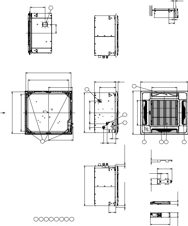
3. DIMENSIONAL DATA
Indoor Unit CS-KS12NB41 & CZ-18BT1U
CS-KS18NB4UW & CZ-18BT1U
7-11/16 |
8 |
|
|
|
|
|
4-29/32 |
View |
|
|
A |
|
|
|
|
|
Ceilingopeningdimensions |
|
|
|
|
|
|
23-5/8(600) |
|
|
|
|
|
|
Suspensionboltpitch |
|
|
|
|
|
|
21-1/32(534) |
|
|
|
|
|
|
|
12-7/16 |
A |
23-5/8 (600) |
Ceiling opening dimensions |
21-1/32 (534) |
Suspension bolt pitch |
Center of panel |
|
|
|
|
|
|
7 |
12-7/8 |
|
|
|
|
|
|
|
Air intake |
Discharge outlet |
Refrigerant tubing (liquid tube) dia. 1/4" (flared) |
Refrigerant tubing (gas tube) dia. 1/2" (flared) |
Drain tube connection port VP20 (outer dia. 1") |
Power supply port |
Suspension bolt hole (4 - 1/2" x 1-1/8" hole) |
Fresh air intake duct connection port (dia. 3-7/8") |
|
|
|
|
|
|
|
|
1 |
2 |
3 |
4 |
5 |
6 |
7 |
8 |
|
|
|
|
|
|
|
|
|
|
11-5/32(283) |
1-3/16(30) |
|
|
|
5 |
8-15/32 |
|
|
|
22-5/8 (575) |
6-11/16 |
|
|
|
24-19/32 (625) |
6-5/16 |
|
|
6 3 |
||
3/32 |
|
|
|||
|
2- |
|
|
|
|
|
|
|
1-25/32 |
Less than 31/32 |
|
|
|
1-25/32 |
4-19/32 |
|
|
|
|
|
|
|
|
5/8 (575) |
31/32 |
22- |
than |
|
Less |
|
3-5/8 |
|
|
|
|
1-3/16 |
|
|
|
|
|
21/32 |
|
|
|
|
|
3-1/8 |
|
The length of the suspension bolts should be selected so that |
there is a gap of 1-3/16" or |
the ceiling (21/32" or more |
below the lower surface of the main unit), as shown in the |
figure at right. If the suspension bolts is too long, it will contact the ceiling panel and the unit |
cannot be installed. |
2 |
24-19/32(625) |
|
|||
13-5/32(334) |
|
||||
|
|
||||
14-3/32 (358) |
|
|
|
|
|
2 |
|
|
2 1 |
|
2 |
25/32 |
|
|
|
|
|
|
|
|
5-9/16 |
|
|
1-9/32 |
|
2-3/4 |
|
|
|
2-3/32 |
|
|
|
3/32 |
|
|
|
|
|
1- |
|
|
7-23/32 |
-27/32 |
|
||
|
1 |
|
|||
Unit : inch (mm)
23

Outdoor Unit CU-KS12NK1A
21-3/16
10-13/16
ID:23/32 19/32-3 
|
3-19/32 |
|
|
|
15/32 |
|
|
|
ID:15/16 |
|
|
- |
|
|
|
2 |
|
|
|
|
10-7/16(265) |
11-13/32 |
12-7/16 |
28-11/32 (720) |
2-1/8 |
|
21-9/16 (548) |
|
5/8 |
Wide tube service valve dia.3/8" (9.52)
Narrow tube service valve dia.1/4" (6.35)
2-5/32
4-9/32 |
6-3/32 |
Unit : inch (mm) (852-0-0010-12600-0)
24
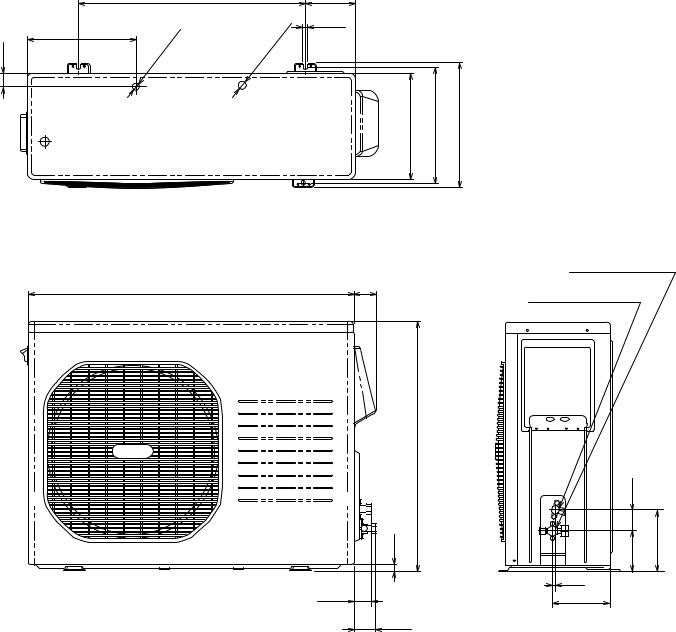
Outdoor Unit CU-KS18NKU
CU-KS18NKUA
|
11-17/32 |
ID:23/32 |
|
|
|
-3/8 |
|
|
1 |
|
|
23-15/16 |
|
5-11/32 |
|
|
|
|
15/32 |
|
|
|
|
ID:15/16 |
|
|
|
- |
|
|
|
|
2 |
|
|
|
|
|
-7/32 (285) |
12-7/32 |
13-5/32 |
|
|
11 |
|
|
Wide tube service valve dia.1/2" (12.70)
34-21/32 (880) |
2-17/32 |
Narrow tube service valve dia.1/4" (6.35)
26-3/8 (670) 2-5/32
23/32 |
4-3/8 |
6-17/32 |
3/32
1-13/16 |
5-23/32 |
2-13/32
Unit : inch (mm) (852-0-0010-13300-0)
25
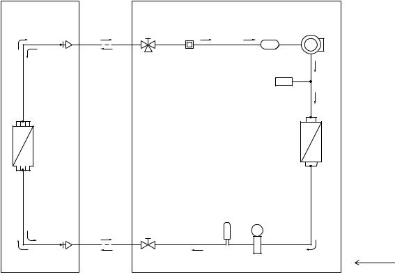
4. REFRIGERANT FLOW DIAGRAM
4-1. Refrigerant Flow Diagram
Indoor Unit CS-KS12NB41 & CZ-18BT1U |
Outdoor Unit CU-KS12NK1A |
Indoor unit |
Outdoor unit |
Heat exchanger
 Strainer
|
Wide tube |
|
|
|
Wide tube |
service |
|
|
Compressor |
valve |
|
Accumulator |
||
|
|
|||
O.D. |
|
Muffler |
|
|
|
|
High pressure |
|
|
3/8" |
|
|
|
|
(9.52 mm) |
|
|
switch |
|
|
|
|
H.P. |
|
|
|
Heat exchanger |
|
|
Narrow |
Electric |
|
|
expansion |
||
|
tube |
||
|
valve |
||
|
service |
||
Narrow tube |
M |
||
valve |
|||
O.D. |
|
Muffler |
|
|
|
||
1/4" |
|
Cooling cycle |
|
(6.35 mm) |
|
||
|
|
26

Indoor Unit CS-KS18NB4UW & CZ-18BT1U Outdoor Unit CU-KS18NKU
CU-KS18NKUA
Indoor unit Outdoor unit
Heat exchanger
 Strainer
|
Wide tube |
|
|
|
Wide tube |
service |
|
|
Compressor |
valve |
|
Accumulator |
||
|
|
|||
O.D. |
|
Muffler |
|
|
|
|
High pressure |
|
|
1/2" |
|
|
|
|
(12.7mm) |
|
|
switch |
|
|
|
|
H.P. |
|
Heat exchanger
|
|
|
|
|
|
Narrow |
|
Electric |
||||||
|
|
|
|
|
|
|
expansion |
|||||||
|
|
|
|
|
|
tube |
|
|||||||
|
|
|
|
|
|
|
valve |
|||||||
|
|
|
|
|
|
service |
|
|||||||
Narrow tube |
|
M |
||||||||||||
valve |
|
|||||||||||||
|
|
|
|
|
|
|
|
|
|
|
|
|
|
|
|
|
|
|
|
|
|
|
|
|
|
|
|
|
|
|
|
|
|
|
|
|
|
|
|
|
|
|
|
|
|
|
|
|
|
|
|
|
|
|
|
|
|
|
|
O.D.
1/4" Cooling cycle
(6.35 mm)
27

5. PERFORMANCE DATA
5-1. Temperature Charts
Indoor Unit CS-KS12NB41 & CZ-18BT1U |
Outdoor Unit CU-KS12NK1A |
 Cooling Characteristics (RH : 46%, Indoor fan speed : High fan) (60Hz, 115V)
(1) Low pressure performance chart
servicevalve |
psig(MPaG) |
|
Lo Fan |
|
Hi Fan |
|
|
||
131 |
|
|
|
|
|
|
|
||
(0.9) |
|
|
|
|
|
.86°F (30°C) |
|
||
|
|
|
|
|
|
|
|||
|
|
Indoor |
Air |
Temp |
|
||||
|
|
|
|
|
|||||
tube |
|
|
|
|
|
|
|
||
|
|
|
|
|
80°F |
(27°C) |
|
||
|
|
|
|
|
|
|
|||
wide |
|
102 |
|
|
|
75°F |
(24°C) |
|
|
|
|
|
|
|
|
||||
at |
|
|
|
|
|
|
|
|
|
|
(0.7) |
|
|
|
|
|
|
|
|
Low pressure |
|
|
|
|
|
|
|
|
|
|
73 |
|
|
|
|
|
|
|
|
|
|
(0.5) |
77 |
86 |
|
|
|
95 |
104 |
|
|
|
(25) |
(30) |
|
|
|
(35) |
(40) |
Outdoor inlet air DB temp. °F(°C)
(2) Operating current performance chart
|
15 |
|
|
|
|
|
|
|
|
|
Lo Fan |
Hi Fan |
|
|
|
(A) |
14 |
|
|
|
|
|
|
|
|
|
|
|
|
(30°C) |
|
current |
|
|
|
|
|
|
|
|
|
|
|
|
.86°F |
||
13 |
|
|
|
Temp |
(27°C) |
||
|
|
|
Air |
80°F |
|||
|
|
|
Indoor |
|
|
(24°C) |
|
Operating |
|
|
|
|
|
||
12 |
|
|
|
|
75°F |
||
|
|
|
|
|
|
||
11 |
|
|
|
|
|
|
|
|
|
|
|
|
|
|
|
|
10 |
77 |
86 |
|
|
95 |
104 |
|
|
(25) |
(30) |
|
|
(35) |
(40) |
Outdoor inlet air DB temp. °F(°C)
(3) Indoor discharge air performance chart
°F(°C) |
68 |
|
|
|
|
|
|
(20) |
Lo Fan |
|
Hi Fan |
|
|
||
|
|
|
|
||||
|
|
|
|
|
|
|
|
temperature |
59 |
|
|
|
|
|
|
(15) |
|
|
|
|
|
|
|
50 |
|
|
|
|
.86°F |
(30°C) |
|
air |
|
Indoor |
Air Temp |
|
|||
(10) |
|
|
|
|
|||
|
|
|
80°F |
(27°C) |
|
||
Indoor discharge |
|
|
|
|
|
||
|
|
|
|
|
|
||
41 |
|
|
|
75°F |
(24°C) |
|
|
|
|
|
|
|
|||
|
|
|
|
|
|
||
(5) |
|
|
|
|
|
|
|
32 |
|
|
|
|
|
|
|
|
(0) |
77 |
86 |
|
|
95 |
104 |
|
|
(25) |
(30) |
|
|
(35) |
(40) |
Outdoor inlet air DB temp. °F(°C)
NOTE
 Check each performance value in test-run mode. Electrical performance values represent a combined indoor/outdoor value.
28
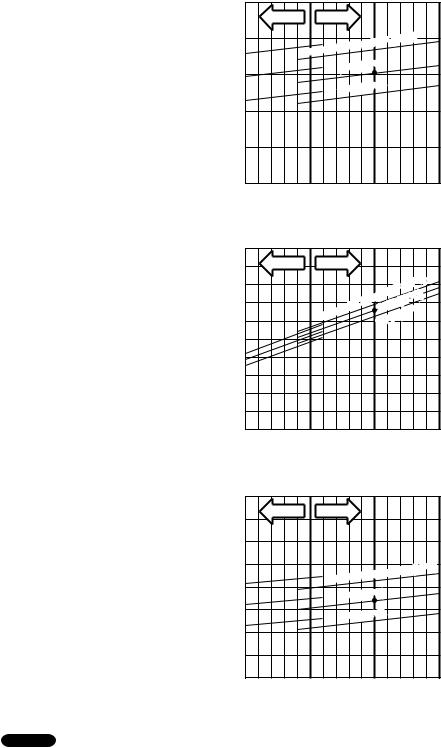
Indoor Unit CS-KS18NB4UW & CZ-18BT1U |
Outdoor Unit CU-KS18NKU or CU-KS18NKUA |
 Cooling Characteristics (RH : 46%, Indoor fan speed : High fan) (60Hz, 230V)
(1) Low pressure performance chart
servicevalve |
psig(MPaG) |
|
Lo Fan |
|
Hi Fan |
|
|
||
131 |
|
|
|
|
|
C) |
|
||
(0.9) |
|
|
|
|
|
.86°F (30° |
|
||
|
Indoor |
Air |
Temp |
|
|||||
|
|
|
|
|
|||||
|
|
|
|
|
|
||||
|
|
|
|
|
|
(27°C) |
|
||
tube |
|
|
|
|
|
80°F |
|
||
|
|
|
|
|
|
|
|||
|
|
|
|
|
|
|
(24°C) |
|
|
wide |
|
|
|
|
|
75°F |
|
||
|
|
|
|
|
|
|
|||
|
102 |
|
|
|
|
|
|
|
|
at |
|
|
|
|
|
|
|
|
|
|
(0.7) |
|
|
|
|
|
|
|
|
Low pressure |
|
|
|
|
|
|
|
|
|
|
73 |
|
|
|
|
|
|
|
|
|
|
(0.5) |
77 |
86 |
|
|
|
95 |
104 |
|
|
|
(25) |
(30) |
|
|
|
(35) |
(40) |
Outdoor inlet air DB temp. °F(°C)
(2) Operating current performance chart
|
10 |
|
|
|
|
|
Lo Fan |
|
Hi Fan |
|
|
(A) |
9 |
|
|
|
(30°C) |
|
|
|
.86°F |
||
|
|
Air |
Temp |
(27°C) |
|
current |
|
|
80°F |
(24°C) |
|
|
|
Indoor |
|||
8 |
|
75°F |
|||
|
|
|
|||
|
|
|
|
|
|
Operating |
7 |
|
|
|
|
6 |
|
|
|
|
|
|
|
|
|
|
|
|
5 |
86 |
|
95 |
104 |
|
77 |
|
|||
|
(25) |
(30) |
|
(35) |
(40) |
Outdoor inlet air DB temp. °F(°C)
(3) Indoor discharge air performance chart
°F(°C) |
68 |
|
|
|
|
|
|
(20) |
Lo Fan |
|
Hi Fan |
|
|
|
|
|
|
|
|
|
|||
|
|
|
|
|
|
|
|
temperature |
59 |
|
|
|
|
|
|
(15) |
|
|
|
|
|
|
|
|
|
|
|
|
|
.86°F (30°C) |
|
50 |
|
|
Indoor |
Air Temp |
|||
|
|
|
|
|
|||
air |
|
|
|
|
|
|
|
(10) |
|
|
80°F (27°C) |
|
|||
Indoor discharge |
|
|
|
75°F |
(24°C) |
|
|
41 |
|
|
|
|
|||
|
|
|
|
|
|
||
(5) |
|
|
|
|
|
|
|
32 |
|
|
|
|
|
|
|
|
(0) |
77 |
86 |
|
|
95 |
104 |
|
|
(25) |
(30) |
|
|
(35) |
(40) |
Outdoor inlet air DB temp. °F(°C)
NOTE
• Check each performance value in test-run mode. Electrical performance values represent a combined indoor/outdoor value.
29

5-2. Cooling Capacity
Indoor Unit |
: CS-KS12NB41 & CZ-18BT1U |
|
|
|
|
|
|
|
|||
Outdoor Unit |
: CU-KS12NK1A |
|
|
|
|
|
|
|
|
|
|
Power Supply : 115V Single Phase 60Hz |
|
|
|
|
|
|
|
|
|||
|
< Cooling Capacity > |
|
|
|
|
|
|
|
|
|
|
|
|
|
|
|
|
|
|
|
|
||
|
RATING CAPACITY: |
11,900 BTU/h |
|
AIR FLOW RATE: |
235 CFM |
||||||
|
INDOOR |
|
|
|
OUTDOOR |
|
|
|
|
||
|
ENT. TEMP. oF (oC) |
|
|
AMBIENT TEMP. oF (oC) |
|
|
|||||
|
WB |
DB |
|
65 |
75 |
85 |
|
95 |
105 |
115 |
|
|
|
|
|
(18.3) |
(23.9) |
(29.4) |
|
(35.0) |
(40.6) |
(46.1) |
|
|
|
|
TC |
8,350 |
8,570 |
8,800 |
|
8,930 |
9,210 |
7,830 |
|
|
|
|
CI |
0.79 |
0.93 |
1.06 |
|
1.16 |
1.25 |
1.07 |
|
|
|
72 (22.2) |
SHC |
6,340 |
6,430 |
6,570 |
|
6,610 |
6,800 |
6,060 |
|
|
59 |
76 (24.4) |
SHC |
7,210 |
7,300 |
7,440 |
|
7,480 |
7,660 |
6,930 |
|
|
(15.0) |
80 (26.7) |
SHC |
8,120 |
8,210 |
8,350 |
|
8,400 |
8,530 |
7,830 |
|
|
|
84 (28.9) |
SHC |
8,350 |
8,570 |
8,800 |
|
8,930 |
9,210 |
7,830 |
|
|
|
88 (31.1) |
SHC |
8,350 |
8,570 |
8,800 |
|
8,930 |
9,210 |
7,830 |
|
|
|
|
TC |
12,230 |
12,030 |
11,790 |
|
11,580 |
10,580 |
7,950 |
|
|
|
|
CI |
0.80 |
0.94 |
1.08 |
|
1.18 |
1.25 |
1.07 |
|
|
|
72 (22.2) |
SHC |
7,070 |
6,930 |
6,840 |
|
6,700 |
6,200 |
4,970 |
|
|
63 |
76 (24.4) |
SHC |
7,940 |
7,800 |
7,710 |
|
7,570 |
7,070 |
5,840 |
|
|
(17.2) |
80 (26.7) |
SHC |
8,850 |
8,720 |
8,580 |
|
8,490 |
7,980 |
6,750 |
|
|
|
84 (28.9) |
SHC |
9,720 |
9,590 |
9,450 |
|
9,360 |
8,850 |
7,620 |
|
|
|
88 (31.1) |
SHC |
10,590 |
10,450 |
10,360 |
|
10,230 |
9,720 |
7,950 |
|
|
|
|
TC |
12,460 |
12,290 |
12,070 |
|
# |
11,900 |
10,700 |
8,040 |
|
|
|
CI |
0.82 |
0.96 |
1.10 |
|
1.20 |
1.25 |
1.07 |
|
|
|
72 (22.2) |
SHC |
5,790 |
5,700 |
5,610 |
|
5,520 |
4,970 |
3,870 |
|
|
67 |
76 (24.4) |
SHC |
6,660 |
6,570 |
6,480 |
|
6,380 |
5,880 |
4,740 |
|
|
(19.4) |
80 (26.7) |
SHC |
7,570 |
7,480 |
7,390 |
|
7,300 |
6,750 |
5,650 |
|
|
|
84 (28.9) |
SHC |
8,440 |
8,350 |
8,260 |
|
8,170 |
7,620 |
6,520 |
|
|
|
88 (31.1) |
SHC |
9,310 |
9,220 |
9,130 |
|
9,040 |
8,490 |
7,390 |
|
|
|
|
TC |
12,640 |
12,490 |
12,300 |
|
12,170 |
10,770 |
8,100 |
|
|
|
|
CI |
0.84 |
0.98 |
1.13 |
|
1.22 |
1.25 |
1.07 |
|
|
|
72 (22.2) |
SHC |
4,460 |
4,420 |
4,330 |
|
4,280 |
3,690 |
2,680 |
|
|
71 |
76 (24.4) |
SHC |
5,330 |
5,290 |
5,200 |
|
5,150 |
4,560 |
3,550 |
|
|
(21.7) |
80 (26.7) |
SHC |
6,250 |
6,200 |
6,110 |
|
6,060 |
5,470 |
4,460 |
|
|
|
84 (28.9) |
SHC |
7,120 |
7,070 |
6,980 |
|
6,930 |
6,340 |
5,330 |
|
|
|
88 (31.1) |
SHC |
7,980 |
7,940 |
7,850 |
|
7,800 |
7,210 |
6,200 |
|
|
|
|
TC |
12,730 |
12,610 |
12,450 |
|
12,370 |
10,780 |
8,120 |
|
|
|
|
CI |
0.86 |
1.01 |
1.15 |
|
1.25 |
1.25 |
1.07 |
|
|
75 |
76 (24.4) |
SHC |
4,050 |
4,010 |
3,960 |
|
3,920 |
3,370 |
2,450 |
|
|
(23.9) |
80 (26.7) |
SHC |
4,970 |
4,920 |
4,880 |
|
4,830 |
4,280 |
3,370 |
|
|
|
84 (28.9) |
SHC |
5,840 |
5,790 |
5,740 |
|
5,700 |
5,150 |
4,240 |
|
|
|
88 (31.1) |
SHC |
6,700 |
6,660 |
6,610 |
|
6,570 |
6,020 |
5,100 |
|
TC : Total Cooling Capacity (BTU/h) SHC : Sensible Heat Capacity (BTU/h)
NOTE
1.Rating conditions (#) : Indoor Unit Entering Air Temp. 80 °F (26.7 °C) DB / 67 °F (19.4 °C) WB
:Outdoor Ambient Temp. 95 °F (35 °C) DB
2.Above data does not take Freeze Prevention Protection during cooling operation into account. For this reason, the value may vary from the actual cooling characteristics.
3.Above data represents the value when the operation frequency of a compressor is fixed.
30
Loading...