


 Loading...
|
|
{TheoryGuide}{Production}{Carestream Health}{Restricted} |
Publication No. TG5258-1 |
|
18JAN08 |
THEORY GUIDE
Restricted
for the
Kodak DirectView CLASSIC/ELITE CR SYSTEM
Service Codes: 5258, 5259
 Important
•Qualified service personnel must repair this equipment.
•When performing the procedures outlined in this document, personnel must always employ safe work practices and wear the appropriate personal protective equipment
(e.g., safety eyewear) in accordance with Company Standard Operating Procedures.
H219_0001GC
© CARESTREAM HEALTH, INC.

THEORY GUIDE
18JAN08 TG5258-1 Page
2 of 113
PLEASE NOTE The information contained herein is based on the experience and knowledge relating to the subject matter gained by Carestream Health, Inc. prior to publication.
No patent license is granted by this information.
Carestream Health, Inc. reserves the right to change this information without notice, and makes no warranty, express or implied, with respect to this information. Carestream Health shall not be liable for any loss or damage, including consequential or special damages, resulting from any use of this information, even if loss or damage is caused by Carestream Health’s negligence or other fault.
This equipment includes parts and assemblies sensitive to damage from electrostatic |
|
discharge. Use caution to prevent damage during all service procedures. |
|
Table of Contents |
|
Description |
Page |
Equipment Description. . . . . . . . . . . . . . . . . . . . . . . . . . . . . . . . . . . . . . . . . . . . . . . . . . |
5 |
Features and Functions . . . . . . . . . . . . . . . . . . . . . . . . . . . . . . . . . . . . . . . . . . . . . |
5 |
Main Subsystems . . . . . . . . . . . . . . . . . . . . . . . . . . . . . . . . . . . . . . . . . . . . . . . . . . |
12 |
Radiography Theory . . . . . . . . . . . . . . . . . . . . . . . . . . . . . . . . . . . . . . . . . . . . . . . . . . . . |
15 |
Comparison of Film/Screen and Computed Radiography (CR) . . . . . . . . . . . . |
15 |
Overview of CR Technology . . . . . . . . . . . . . . . . . . . . . . . . . . . . . . . . . . . . . . . . . |
19 |
Operations . . . . . . . . . . . . . . . . . . . . . . . . . . . . . . . . . . . . . . . . . . . . . . . . . . . . |
19 |
Exposing the STORAGE PHOSPHOR SCREEN. . . . . . . . . . . . . . . . . . . . . . |
19 |
Stimulating the PHOSPHOR. . . . . . . . . . . . . . . . . . . . . . . . . . . . . . . . . . . . . . |
21 |
Changing Light Energy to an Analog Signal. . . . . . . . . . . . . . . . . . . . . . . . |
22 |
Changing Analog Signals to Digital Signals . . . . . . . . . . . . . . . . . . . . . . . . |
23 |
Processing the Digital Image. . . . . . . . . . . . . . . . . . . . . . . . . . . . . . . . . . . . . |
24 |
Sequence of Operation. . . . . . . . . . . . . . . . . . . . . . . . . . . . . . . . . . . . . . . . . . . . . . . . . . |
25 |
Overview of Workflow Using the CLASSIC/ELITE CR SYSTEM . . . . . . . . . . . . |
25 |
Before Loading the CASSETTE. . . . . . . . . . . . . . . . . . . . . . . . . . . . . . . . . . . . . . . |
26 |
Loading the CASSETTE . . . . . . . . . . . . . . . . . . . . . . . . . . . . . . . . . . . . . . . . . . . . . |
26 |
Removing the PLATE from the CASSETTE . . . . . . . . . . . . . . . . . . . . . . . . . . . . . |
28 |
Scanning the SCREEN . . . . . . . . . . . . . . . . . . . . . . . . . . . . . . . . . . . . . . . . . . . . . . |
29 |
Erasing the SCREEN . . . . . . . . . . . . . . . . . . . . . . . . . . . . . . . . . . . . . . . . . . . . . . . |
30 |
Inserting the PLATE back into the CASSETTE SHELL . . . . . . . . . . . . . . . . . . . |
31 |
Removing the CASSETTE . . . . . . . . . . . . . . . . . . . . . . . . . . . . . . . . . . . . . . . . . . . |
31 |
STORAGE PHOSPHOR CASSETTE . . . . . . . . . . . . . . . . . . . . . . . . . . . . . . . . . . . . . . . |
32 |
Overview. . . . . . . . . . . . . . . . . . . . . . . . . . . . . . . . . . . . . . . . . . . . . . . . . . . . . . . . . . |
32 |
Size and Resolution of SCREENS. . . . . . . . . . . . . . . . . . . . . . . . . . . . . . . . . . . . . |
34 |
Fast Scan / Slow Scan Directions. . . . . . . . . . . . . . . . . . . . . . . . . . . . . . . . . . . . . |
36 |

THEORY GUIDE
18JAN08 TG5258-1 Page
3 of 113
Image Matrix Size . . . . . . . . . . . . . . . . . . . . . . . . . . . . . . . . . . . . . . . . . . . . . . . . . . |
37 |
Reading the BAR CODE LABEL of the CASSETTE . . . . . . . . . . . . . . . . . . . . . . |
40 |
CASSETTE HANDLING . . . . . . . . . . . . . . . . . . . . . . . . . . . . . . . . . . . . . . . . . . . . . . . . . . |
42 |
Overview. . . . . . . . . . . . . . . . . . . . . . . . . . . . . . . . . . . . . . . . . . . . . . . . . . . . . . . . . . |
42 |
CASSETTE Load . . . . . . . . . . . . . . . . . . . . . . . . . . . . . . . . . . . . . . . . . . . . . . . . . . . |
44 |
EXTRACTION BAR MOTOR AY . . . . . . . . . . . . . . . . . . . . . . . . . . . . . . . . . . . . . . . |
48 |
CLAMP MOTOR . . . . . . . . . . . . . . . . . . . . . . . . . . . . . . . . . . . . . . . . . . . . . . . . . . . . |
50 |
PLATE HANDLING . . . . . . . . . . . . . . . . . . . . . . . . . . . . . . . . . . . . . . . . . . . . . . . . . |
52 |
Optical . . . . . . . . . . . . . . . . . . . . . . . . . . . . . . . . . . . . . . . . . . . . . . . . . . . . . . . . . . . . . . . |
53 |
Overview. . . . . . . . . . . . . . . . . . . . . . . . . . . . . . . . . . . . . . . . . . . . . . . . . . . . . . . . . . |
53 |
LASER . . . . . . . . . . . . . . . . . . . . . . . . . . . . . . . . . . . . . . . . . . . . . . . . . . . . . . . . . . . |
55 |
GALVO . . . . . . . . . . . . . . . . . . . . . . . . . . . . . . . . . . . . . . . . . . . . . . . . . . . . . . . . . . |
57 |
COLLECTOR and PHOTOMULTIPLIER TUBE (PMT). . . . . . . . . . . . . . . . . . . . . . |
61 |
Scan/Erase . . . . . . . . . . . . . . . . . . . . . . . . . . . . . . . . . . . . . . . . . . . . . . . . . . . . . . . . . . . . |
67 |
Overview. . . . . . . . . . . . . . . . . . . . . . . . . . . . . . . . . . . . . . . . . . . . . . . . . . . . . . . . . . |
67 |
PLATE SUPPORT AY - Version 1 . . . . . . . . . . . . . . . . . . . . . . . . . . . . . . . . . . . . . |
69 |
PLATE SUPPORT AY - Version 2 . . . . . . . . . . . . . . . . . . . . . . . . . . . . . . . . . . . . . |
70 |
LEAD SCREW . . . . . . . . . . . . . . . . . . . . . . . . . . . . . . . . . . . . . . . . . . . . . . . . . . . . . |
71 |
EXTRACTION BAR . . . . . . . . . . . . . . . . . . . . . . . . . . . . . . . . . . . . . . . . . . . . . . . . . |
71 |
REFERENCE SENSOR S5 . . . . . . . . . . . . . . . . . . . . . . . . . . . . . . . . . . . . . . . . . . . |
73 |
PLATE PRESENT SENSOR S6 . . . . . . . . . . . . . . . . . . . . . . . . . . . . . . . . . . . . . . . |
73 |
SLOW SCAN MOTOR . . . . . . . . . . . . . . . . . . . . . . . . . . . . . . . . . . . . . . . . . . . . . . . |
73 |
ENCODER. . . . . . . . . . . . . . . . . . . . . . . . . . . . . . . . . . . . . . . . . . . . . . . . . . . . . . . . . |
77 |
ERASE AY . . . . . . . . . . . . . . . . . . . . . . . . . . . . . . . . . . . . . . . . . . . . . . . . . . . . . . . . |
78 |
LAMP CURRENT SENSORS CS1 - CS5 . . . . . . . . . . . . . . . . . . . . . . . . . . . . . . . . |
79 |
Imaging Sequence . . . . . . . . . . . . . . . . . . . . . . . . . . . . . . . . . . . . . . . . . . . . . . . . . . . . . |
80 |
Overview. . . . . . . . . . . . . . . . . . . . . . . . . . . . . . . . . . . . . . . . . . . . . . . . . . . . . . . . . . |
80 |
Scanning the SCREEN - Slow Scan/Fast Scan . . . . . . . . . . . . . . . . . . . . . . . . . . |
81 |
Obtaining the Image Data . . . . . . . . . . . . . . . . . . . . . . . . . . . . . . . . . . . . . . . . . . . |
83 |
Processing the Data . . . . . . . . . . . . . . . . . . . . . . . . . . . . . . . . . . . . . . . . . . . . . . . . |
85 |
Processing the Image. . . . . . . . . . . . . . . . . . . . . . . . . . . . . . . . . . . . . . . . . . . . . . . |
86 |
Logic and Control . . . . . . . . . . . . . . . . . . . . . . . . . . . . . . . . . . . . . . . . . . . . . . . . . . . . . . |
88 |
Overview. . . . . . . . . . . . . . . . . . . . . . . . . . . . . . . . . . . . . . . . . . . . . . . . . . . . . . . . . . |
88 |
Operator Input Components . . . . . . . . . . . . . . . . . . . . . . . . . . . . . . . . . . . . . . . . . |
89 |
MONITOR . . . . . . . . . . . . . . . . . . . . . . . . . . . . . . . . . . . . . . . . . . . . . . . . . . . . . |
89 |
LOCAL USER INTERFACE (LUI) . . . . . . . . . . . . . . . . . . . . . . . . . . . . . . . . . . |
92 |
BOARDS . . . . . . . . . . . . . . . . . . . . . . . . . . . . . . . . . . . . . . . . . . . . . . . . . . . . . . . . . . |
93 |
Distribution of Images to the Network . . . . . . . . . . . . . . . . . . . . . . . . . . . . . . . . . |
96 |
Overview. . . . . . . . . . . . . . . . . . . . . . . . . . . . . . . . . . . . . . . . . . . . . . . . . . . . . . |
96 |
Sequence of Operation. . . . . . . . . . . . . . . . . . . . . . . . . . . . . . . . . . . . . . . . . . |
97 |

THEORY GUIDE
18JAN08 TG5258-1 Page
4 of 113
Power Distribution . . . . . . . . . . . . . . . . . . . . . . . . . . . . . . . . . . . . . . . . . . . . . . . . . . . 99
Overview. . . . . . . . . . . . . . . . . . . . . . . . . . . . . . . . . . . . . . . . . . . . . . . . . . . . . . . . . . 99
POWER SUPPLY . . . . . . . . . . . . . . . . . . . . . . . . . . . . . . . . . . . . . . . . . . . . . . . . . . . 100
Power Distribution . . . . . . . . . . . . . . . . . . . . . . . . . . . . . . . . . . . . . . . . . . . . . . . . . 101
INTERLOCK . . . . . . . . . . . . . . . . . . . . . . . . . . . . . . . . . . . . . . . . . . . . . . . . . . . . . . . 103
TRANSFORMER T1 . . . . . . . . . . . . . . . . . . . . . . . . . . . . . . . . . . . . . . . . . . . . . . . . . 104
Logs . . . . . . . . . . . . . . . . . . . . . . . . . . . . . . . . . . . . . . . . . . . . . . . . . . . . . . . . . . . . . . . . . 105
Overview. . . . . . . . . . . . . . . . . . . . . . . . . . . . . . . . . . . . . . . . . . . . . . . . . . . . . . . . . . 105
Error and Activity Log . . . . . . . . . . . . . . . . . . . . . . . . . . . . . . . . . . . . . . . . . . . . . . 106
Actuation Log . . . . . . . . . . . . . . . . . . . . . . . . . . . . . . . . . . . . . . . . . . . . . . . . . . . . . 107
Glossary . . . . . . . . . . . . . . . . . . . . . . . . . . . . . . . . . . . . . . . . . . . . . . . . . . . . . . . . . . . . . . 108

THEORY GUIDE |
Equipment Description |
|
|
18JAN08 TG5258-1 Page
5 of 113
Section 1: Equipment Description
Features and Functions
The Kodak DirectView CLASSIC/ELITE CR SYSTEM is a LASER SCANNER that reads a latent image made on a STORAGE PHOSPHOR SCREEN during an X-ray exam and provides a digital image. Physicians and radiologists can then view, improve, store and make a print of the image, and send the image across a computer network.
Feature |
Function |
|
SCANNER for |
• Size: 43.8 x 60.3 cm (19.0 x 23.75 in.) |
|
the CLASSIC or |
• single CASSETTE load with integrated LOCAL USER INTERFACE |
|
ELITE CR |
||
• uses DirectView CR CASSETTES |
||
SYSTEM |
||
|
• ELITE CR SYSTEM provides maximum CASSETTE throughput |
|
|
capability |
|
|
• CLASSIC CR SYSTEM provides throughput of approximately 25 - 30% |
|
|
lower than the ELITE CR SYSTEM |
|
|
|
|
BAR CODE |
• EXTERNAL BAR CODE READER: |
|
READERS |
– hand-held READER |
|
|
||
|
– used to scan the BAR CODE LABEL on CASSETTES and other |
|
|
bar codes used for entering data |
|
|
• INTERNAL BAR CODE READER: |
|
|
– automatically scans the BAR CODE LABEL on CASSETTES that |
|
|
are loaded |
|
|
– provides information about the size, speed, and serial number of |
|
|
the CASSETTE |
|
|
|

THEORY GUIDE |
Equipment Description |
|
|
18JAN08 TG5258-1 Page
6 of 113
Feature |
Function |
|
WORKFLOW |
MONITOR - options: |
|
and IMAGE |
• 17 in. FLAT PANEL DISPLAY without TOUCH SCREEN - requires use |
|
VIEWING |
of KEYBOARD |
|
CONSOLE |
• 19 in. FLAT PANEL DISPLAY with TOUCH SCREEN |
|
(WAIV) |
||
|
•allows the operator to touch or click areas displayed on the screen to:
–enter exam and patient information
–view and improve images
•allows the FE to do service diagnostics
EXTERNAL PC:
•includes software for:
–acquiring images from the CLASSIC/ELITE CR SYSTEM
–processing images
–providing communication with external devices and the computer network
•available at all times to the FE
Software |
• new EVP Plus Software |
|
Options |
• Administrative Analysis and Reporting |
|
Available |
||
• Total Quality Tool |
||
|
||
|
• Mammography Option - outside US and Canada |
|
|
• Software Refresh |
|
|
|
|
Furniture |
• FLOOR STAND |
|
Options |
• WALL STAND |
|
Available |
||
• either holds MONITOR, KEYBOARD, MOUSE, and BAR CODE |
||
|
||
|
READER |
|
|
• FLOOR STAND also holds 10 CASSETTES |

|
THEORY GUIDE |
Equipment Description |
||
|
|
|
|
|
18JAN08 |
|
|
|
|
TG5258-1 |
|
Feature |
Function |
|
Page |
|
|
|
|
|
Kodak |
A device that is installed on the wall in an area separate from the |
||
7 of 113 |
|
|||
|
|
DirectView |
CLASSIC/ELITE CR SYSTEM, used for viewing images and entering |
|
|
|
REMOTE |
data. The ROP includes: |
|
|
|
OPERATIONS |
• computer running Microsoft Windows XP |
|
|
|
PANEL (ROP) |
• TOUCH SCREEN MONITOR - SVGA device with a 1024 x 768 pixel |
|
|
|
|
||
|
|
|
resolution |
|
|
|
|
• EXTERNAL BAR CODE READER - can read all formats identified for |
|
|
|
|
the hand-held BAR CODE READER on the CLASSIC/ELITE CR |
|
|
|
|
SYSTEM |
|
The ROP allows operators to:
•enter patient, exam, and CASSETTE (PEC) data into a CLASSIC/ ELITE CR SYSTEM
•check patient data
•view scanned X-ray images
•send images to other nodes on the network
The PEC data entered through an ROP and sent across the network is associated with the correct image.

|
THEORY GUIDE |
Equipment Description |
||
|
|
|
|
|
18JAN08 |
|
|
|
|
TG5258-1 |
|
Feature |
Function |
|
Page |
|
|
|
|
|
Configurations |
• STANDALONE - the CLASSIC/ELITE CR SYSTEM is not connected |
||
8 of 113 |
|
|||
|
|
|
for use with other CR SYSTEMS on a network: |
|
|
|
|
– CLASSIC/ELITE CR SYSTEM supports use with a maximum of 10 |
|
|
|
|
REMOTE DEVICES |
|
|
|
|
– network connects to WORKSTATIONS for viewing, or reading the |
|
|
|
|
images, and to PRINTERS to obtain hardcopy output |
|
|
|
|
• CAPTURE LINK SYSTEM - uses a CAPTURE LINK SERVER to |
|
|
|
|
support shared use of 2 - 5 CR SYSTEMS on a network |
|
|
|
|
• SIMPLE CAPTURE LINK - software option allows shared use of 2 CR |
|
|
|
|
SYSTEMS on a network without using a CAPTURE LINK SERVER |
|
|
|
|
• In a SIMPLE or CAPTURE LINK SYSTEM: |
|
|
|
|
– CR SYSTEMS configured can be Kodak DirectView CR 825/850/ |
|
|
|
|
950/975 SYSTEMS or CLASSIC/ELITE CR SYSTEMS |
|
|
|
|
– up to 20 remote devices can be configured for use |
|
|
|
|
– workflow is distributed by allowing patient data, CASSETTE ID |
|
|
|
|
information, CASSETTE scanning, and image review functions to |
|
|
|
|
be shared between CR SYSTEMS and remote devices |
|
|
|
|
– CR SYSTEMS and remote devices can only share information and |
|
|
|
|
function together within the same SIMPLE or CAPTURE LINK |
|
|
|
|
SYSTEM |
|
|
|
|
– CR SYSTEMS network connect to WORKSTATIONS for viewing or |
|
|
|
|
reading the images and/or to PRINTERS to obtain hardcopy output |
|
Remote devices include:
•REMOTE OPERATION PANELS (ROP)
•Customer provided PC using REMOTE ACCESS SOFTWARE (RAS) allows the PC to be used:
–as a REMOTE PATIENT DATA ENTRY STATION (RPDES)
–for performing REMOTE KEY OPERATOR functions.
|
|
THEORY GUIDE |
|
Equipment Description |
||
|
18JAN08 |
|
|
|
|
|
|
|
|
|
|
|
|
|
TG5258-1 |
|
Feature |
|
Function |
|
|
Page |
|
|
|
|
|
|
|
Network |
All CLASSIC/ELITE CR SYSTEMS and ROP devices: |
|||
|
9 of 113 |
|
||||
|
|
|
Communications |
• |
connect to the 10 Base-T, 100 Base-T, or 1000 Base-T Ethernet |
|
|
|
|
|
|
network of the site |
|
|
|
|
|
• |
can send information to all networked DICOM digital imaging |
|
|
|
|
|
|
equipment that is qualified with the CLASSIC/ELITE CR SYSTEM |
|
|
|
|
|
• use CATEGORY 5 CABLES to connect to the network |
||
|
|
|
|
• |
use a gateway device qualified by Carestream Health to enable access |
|
|
|
|
|
|
to the HIS/RIS system. The customer must provide this device |
|
|
|
|
|
|
|
|
|
|
|
On-site Service |
• CASTERS allow the CLASSIC/ELITE CR SYSTEM to be moved for |
||
|
|
|
|
|
service without leveling |
|
|
|
|
|
• DATA PLATES and MODIFICATION LABELS are located for easy |
||
|
|
|
|
|
access and viewing |
|
|
|
|
|
• PLUGS and CONNECTORS are identified |
||
|
|
|
|
• |
data in the Error and Activity logs can be sorted by field for |
|
|
|
|
|
|
troubleshooting, for example, by date and error code number |
|
|
|
|
|
• |
FEs can view internal diagnostics, including error codes, component |
|
|
|
|
|
|
tests, and tests of the SENSORS from the MONITOR |
|
|
|
|
|
|
|
|
|
|
|
|
|
|
|

|
THEORY GUIDE |
|
Equipment Description |
||
|
|
|
|
|
|
18JAN08 |
|
|
|
|
|
TG5258-1 |
|
Feature |
|
Function |
|
Page |
|
|
|
|
|
|
Remote Service |
• |
remote access options: |
||
10 of 113 |
|
||||
|
|
|
|
– dedicated MODEM connected to the CLASSIC/ELITE CR SYSTEM |
|
|
|
|
|
– MODEM SERVER provided by the customer |
|
|
|
|
• |
one point of access to the service functions of all CLASSIC/ELITE CR |
|
|
|
|
|
SYSTEMS on the customer network from the remote service access |
|
|
|
|
|
connection |
|
|
|
|
• |
access to all service functions, except running the SCAN/ERASE |
|
|
|
|
|
subsystem |
|
|
|
|
• |
remote service: |
|
|
|
|
|
– installing software |
|
|
|
|
|
– setting up the configuration for the CLASSIC/ELITE CR SYSTEM |
|
|
|
|
|
– retrieving and clearing Error and Activity Logs |
|
|
|
|
|
– retrieving Image Processing Library (IPL) diagnostic images |
|
 Note
Note
FEs providing remote service cannot view the information about the patient on images.
|
|
THEORY GUIDE |
|
|
|
Equipment Description |
||
|
18JAN08 |
|
|
|
|
|
|
|
|
|
The following table describes the specifications for the number of CASSETTES per hour: |
||||||
|
TG5258-1 |
|
||||||
|
Page |
|
|
|
|
|
|
|
|
11 of 113 |
|
|
|
|
|
|
|
|
|
|
|
CLASSIC CR SYSTEM |
ELITE CR SYSTEM |
|
||
|
|
|
|
|
|
|
|
|
|
|
|
|
High Speed and |
|
High Speed and |
|
|
|
|
|
Size |
Reduced Border |
Standard Speed |
Reduced Border |
Standard Speed |
|
|
|
|
|
Scan Mode |
|
Scan Mode |
|
|
|
|
|
|
|
|
|
|
|
|
|
|
24 x 18 GP |
77 |
77 |
100 |
100 |
|
|
|
|
|
|
|
|
|
|
|
|
|
24 x 30 GP |
58 |
58 |
76 |
76 |
|
|
|
|
|
|
|
|
|
|
|
|
|
24 x 18 HR |
77 |
77 |
101 |
101 |
|
|
|
|
|
|
|
|
|
|
|
|
|
24 x 30 HR |
58 |
58 |
76 |
76 |
|
|
|
|
|
|
|
|
|
|
|
|
|
24 x 18 EHR-M |
60 |
60 |
79 |
79 |
|
|
|
|
|
|
|
|
|
|
|
|
|
24 x 18 EHR-M2 |
60 |
60 |
79 |
79 |
|
|
|
|
|
|
|
|
|
|
|
|
|
24 x 30 EHR-M |
45 |
45 |
58 |
58 |
|
|
|
|
|
|
|
|
|
|
|
|
|
24 x 30 EHR-M2 |
45 |
45 |
58 |
58 |
|
|
|
|
|
|
|
|
|
|
|
|
|
30 x 15 GP |
92 |
92 |
122 |
122 |
|
|
|
|
|
|
|
|
|
|
|
|
|
35 x 35 GP |
77 |
53 |
102 |
71 |
|
|
|
|
|
|
|
|
|
|
|
|
|
35 x 43 GP |
69 |
46 |
90 |
61 |
|
|
|
|
|
|
|
|
|
|
|
|
|
35 x 35 GP+ |
53 |
53 |
70 |
70 |
|
|
|
|
|
|
|
|
|
|
|
|
|
35 x 43 GP+ |
46 |
46 |
61 |
61 |
|
|
|
|
|
|
|
|
|
|
|
|
|
35 x 43 LONG- |
66 |
66 |
87 |
87 |
|
|
|
|
LENGTH |
|
|
|
|
|
|
|
|
CASSETTE |
|
|
|
|
|
|
|
|
|
|
|
|
|
|
|
|
|
35 x 84 GP LLI |
68 |
68 |
88 |
88 |
|
|
|
|
|
|
|
|
|
|
|
|
|
|
Tolerance is ± 5 |
|
|
|
|
|
|
|
|
|
|
|
|
|
|
|
|
|
|
|
|
|
|

|
THEORY GUIDE |
|
|
|
|
|
|
|
Equipment Description |
18JAN08 |
Main Subsystems |
|
|
|
|
|
|
||
TG5258-1 |
|
|
|
|
|
|
|||
Page |
|
|
|
|
|
|
|
|
|
12 of 113 |
|
|
|
|
|
|
|
|
|
|
|
|
EXTERNAL |
|
|
To Network |
|
|
|
|
|
MONITOR |
EXTERNAL |
|
|
|
|||
|
|
BARCODE |
|
|
|
||||
|
|
|
PC |
|
|
|
|||
|
|
|
READER |
|
|
|
|
||
|
|
|
|
|
|
|
|
||
|
|
|
|
|
|
|
SLOW |
IEB |
|
|
|
|
|
|
|
|
SCAN |
|
|
|
|
|
|
|
|
|
BOARD |
|
|
|
|
|
|
MINI - MCB |
RS-232 |
ENCODER |
|
||
|
|
|
|
A2 |
|
||||
|
|
|
|
|
BOARD |
|
|
||
|
|
|
|
|
|
|
|
GALVO |
|
|
|
|
|
|
A1 |
|
SLOW |
|
|
|
|
|
|
|
|
|
|
|
|
|
|
|
|
|
|
|
SCAN |
|
|
|
|
|
|
|
|
|
MOTOR |
|
|
|
|
|
|
|
|
|
|
|
2 PMTS |
|
|
|
|
|
|
|
LASER |
|
PMT/DAS |
|
|
ERASE |
|
|
|
|
DIODE |
|
|
|
|
|
|
|
|
DRIVER |
|
BOARD |
|
|
|
LAMPS |
|
|
|
|
|
||
|
|
|
|
|
|
BOARD |
|
A5 |
|
|
|
|
|
|
|
|
|
||
|
|
|
|
|
|
|
A17 |
|
|
|
|
|
|
INTERNAL |
|
LASER |
|
COLLECTOR |
|
|
|
|
|
|
|
|
|||
|
|
|
|
BARCODE |
|
|
|
|
|
|
|
|
|
READER |
|
|
LOCAL |
|
|
|
|
|
|
|
|
|
|
|
|
|
|
|
|
|
|
|
|
USER |
Hospital |
|
|
|
|
|
|
|
|
INTERFACE |
|
|
|
|
|
|
|
|
|
Network |
|
|
|
|
|
|
|
|
|
|
|
|
AC Power |
VOLTAGE |
ISOLATION |
|
POWER |
|
|
||
|
SELECTION |
|
SUPPLY |
|
|
||||
|
90-264 VAC |
TRANSFORMER |
|
|
|
||||
|
JUMPERS |
|
PS1 |
|
|
||||
|
|
|
|
|
|
|
|||
|
H219_7500DC |
|
|
|
|
|
|
|
|

THEORY GUIDE |
Equipment Description |
|
|
18JAN08 TG5258-1 Page 13 of 113
Subsystem |
|
Description |
See: |
CASSETTE |
• includes: |
STORAGE |
|
|
|
– STORAGE PHOSPHOR |
PHOSPHOR |
|
|
CASSETTE |
|
|
|
SCREEN that captures and stores the X-ray |
|
|
|
|
|
|
|
image for processing |
|
|
|
– CASSETTE SHELL that holds the PLATE |
|
|
• |
available in 5 sizes and 3 resolutions (GP, HR, |
|
|
|
and EHR) |
|
|
|
|
|
CASSETTE |
• allows the operator to load the CASSETTE into |
CASSETTE |
|
HANDLING |
|
the CLASSIC/ELITE CR SYSTEM |
HANDLING |
|
• removes the PLATE from the CASSETTE SHELL |
|
|
|
• |
after scanning, installs the PLATE in the |
|
|
|
CASSETTE SHELL |
|
|
• allows the CASSETTE to be removed from the |
|
|
|
|
CLASSIC/ELITE CR SYSTEM |
|
|
|
|
|
Optical |
• controls and moves the laser beam to the |
Optical |
|
|
|
SCREEN |
|
|
• |
captures the blue light emitted from the SCREEN |
|
|
|
|
|
Scan/Erase |
• moves the PLATE at a uniform speed: |
Scan/Erase |
|
|
|
– through the scanning area |
|
|
|
– to the erase position |
|
|
• removes the residual image on the SCREEN by |
|
|
|
|
exposing it to maximum light |
|
|
• inserts the PLATE into the CASSETTE SHELL |
|
|
|
|
again |
|
|
|
|
|
Imaging |
• assembles the data from the SCREEN and |
Imaging |
|
|
|
changes it to digital format |
Sequence |
|
• |
processes the image |
|
|
|
|
|

THEORY GUIDE |
Equipment Description |
|
|
18JAN08 TG5258-1 Page 14 of 113
Subsystem |
|
Description |
See: |
Logic and Control |
• processes commands from the operator |
Logic and |
|
|
• |
controls the operation of all subsystems |
Control |
|
|
||
|
• |
sends processed images to the network for |
|
|
|
distribution |
|
|
|
|
|
Power Distribution |
• provides power for all subsystems |
Power |
|
|
• has an INTERLOCK SWITCH that actuates when |
Distribution |
|
|
|
||
|
|
the FRONT COVER is removed |
|
|
|
|
|
Error and Activity |
• records logs of errors in the system |
Logs |
|
Logs |
• |
records user actions |
|
|
|
||
|
|
|
|

THEORY GUIDE |
Radiography Theory |
|
|
18JAN08 TG5258-1 Page 15 of 113
Section 2: Radiography Theory
Comparison of Film/Screen and Computed Radiography (CR)
X-RAY |
latent image |
visible image |
TUBE |
(On Film) |
(On Film) |
FILM/ |
|
FILM PROCESSING |
SCREEN
AERIAL
IMAGE
|
latent image |
visible image |
FINAL VISIBLE |
X-RAY |
IMAGE |
||
TUBE |
(Storage Phosphor) |
(CRT) |
(Film or Viewer) |
STORAGE |
|
|
ENHANCED |
CONVERSIONS |
|
PROCESSING |
|
PHOSPHOR |
|
||
|
|
|
|
SCREEN |
|
|
|
AERIAL
IMAGE
H194_5012HC
X-rays are used in medical imaging to make an image of given body parts on a surface, which can be read by a Radiologist or other medical personnel. The available systems for capturing these images are:
•Screen/film - captures a projection image on an X-ray film
•Computed Radiography (CR) - captures a digital image

THEORY GUIDE |
Radiography Theory |
|
|
18JAN08 TG5258-1 Page 16 of 113
The following phases are necessary to capture and process projection radiographs for both screen/film systems and CR systems:
Phase of Image Capture |
|
Description |
Phase 1 - |
In both screen/film and CR SYSTEMS: |
|
Making the aerial image |
• |
an X-ray TUBE emits X-rays in the direction of an IMAGE |
|
|
RECEPTOR |
|
• |
when the X-rays reach the body of the patient, some are |
|
|
absorbed by the patient and some are not. The result is an |
|
|
“aerial” image with varying degrees of X-ray power (varying |
|
|
numbers of X-ray PHOTONS) |
|
|
|
Phase 2 - |
When the IMAGE RECEPTOR is exposed to the X-rays in the |
|
Capturing the latent image |
aerial image, a latent image is captured on the RECEPTOR: |
|
|
• |
screen/film systems - image is captured on sensitized |
|
|
radiographic film |
|
• CR SYSTEMS - image is captured on a STORAGE |
|
|
|
PHOSPHOR SCREEN. The X-ray PHOTONS that reach the |
|
|
SCREEN charge the PHOSPHOR, making a latent image |
|
|
on the screen |
|
|
|
Phase 3 - |
The latent image must be changed to a visible image, which |
|
Capturing, changing, and |
can be read by the Radiologist, moved from one place to |
|
storing the visible image |
another, and stored for use at another time: |
|
|
• |
screen/film systems - radiographic film is processed through |
|
|
chemicals and the latent image is fixed onto the film |
|
• CR SYSTEMS - the latent image on the STORAGE |
|
|
|
PHOSPHOR SCREEN is scanned by a laser beam, which |
|
|
stimulates the charged PHOSPHOR on the SCREEN. Blue |
|
|
light is emitted from the stimulated PHOSPHOR, assembled, |
|
|
and changed into analog electrical signals. The analog |
|
|
image is then changed into digital signals and processed. |
|
|
The digital image is stored and displayed by a computer |
|
|
system and can be routed to other computers and |
|
|
PRINTERS through a network |
|
|
|

THEORY GUIDE |
Radiography Theory |
|
|
18JAN08 TG5258-1 Page 17 of 113
The following table compares the analog and digital health image capture systems.
Analog Screen/Film Systems |
|
Digital CR Systems |
Uses “Rare Earth” SCREENS - |
Uses a BARIUM FLOUROHALIDE STORAGE |
|
GADOLINIUM OXYSULFIDE or |
PHOSPHOR SCREEN. |
|
LANTHANUM OXYBROMIDE. |
|
|
|
|
|
Speed range from 100 - 1000. |
Phosphor SCREEN types. Use: |
|
|
• |
General Purpose (GP) for most general |
|
|
radiography exams |
|
• |
High Resolution (HR) for general |
|
|
radiography extremity exams |
|
• Enhanced High Resolution (EHR) for |
|
|
|
mammography exams |
|
|
|
Film processing parameters are important |
No film processing is necessary. |
|
in determining the quality of the image, |
|
|
for example: chemical temperature and |
|
|
timing. |
|
|
|
|
|
It is hard to obtain the same print quality |
The user can print a copy of the digital image |
|
when copies are necessary because of |
at any time with a consistent level of quality. |
|
variations in GENERATORS, |
|
|
PROCESSORS, positions, procedures, |
|
|
and conditions for developing the film. |
|
|
|
|
|
Overexposing or underexposing an image |
Exposure factors do not normally make it |
|
normally makes it necessary to expose |
necessary to expose the patient to ionizing |
|
the patient to ionizing radiation again. |
radiation again. |
|
|
|
|
Image quality is changed by conditions in |
Image quality is not changed by conditions in |
|
the environment, for example temperature |
the environment. |
|
or humidity. |
|
|
|
|
|
The image cannot be viewed in more |
CR images can be viewed at more than one |
|
than one place at a time. |
place at the same time, in the same building or |
|
|
in remote nodes on the network. |
|
|
|
|

THEORY GUIDE |
Radiography Theory |
|
|
18JAN08 TG5258-1 Page 18 of 113
|
Analog Screen/Film Systems |
Digital CR Systems |
|
• |
Recording medium - film |
• Recording medium - STORAGE |
|
• |
Output medium - film |
PHOSPHOR SCREEN |
|
• Output medium - film, paper, digital display |
|||
• |
Storing medium - film |
||
• Storing medium - digital |
|||
|
|
||
|
|
||
Image density and contrast are controlled |
Density and contrast are controlled by image |
||
by kilovolts peak (kvP), milliampere |
processing parameters. kvP, and mA.s continue |
||
seconds (mA.s), and film type. |
to be important image control factors for details |
||
|
|
and noise in the digital image. |
|
|
|
||
Viewing quality can only be improved by |
Digital images can be improved by processing |
||
increasing the brightness of the LAMP |
on a computer to change the density, contrast, |
||
that illuminates the film. |
sharpness, and other factors. |
||
|
|
||
The quality of films that are not exposed |
Images that were not exposed correctly can be |
||
correctly cannot be improved. |
improved. For example, software parameters |
||
|
|
can improve image density and contrast. |
|
|
|
|
|
THEORY GUIDE |
Radiography Theory |
|
|
18JAN08 TG5258-1 Page 19 of 113
Overview of CR Technology
Operations
The following operations are necessary to capture the latent image in the STORAGE
PHOSPHOR SCREEN and change it to a digital image that can be viewed on a computer screen and sent to a PRINTER.
•Exposing the STORAGE PHOSPHOR SCREEN
•Stimulating the PHOSPHOR
•Changing Light Energy to an Analog Signal
•Changing Analog Signals to Digital Signals
•Processing the Digital Image
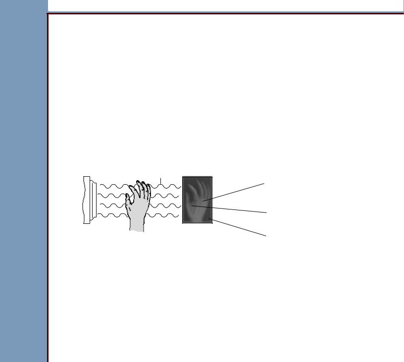
Exposing the STORAGE PHOSPHOR SCREEN
X-RAY TUBE
aerial
latent
image
image
STORAGE PHOSPHOR SCREEN Charged storage phosphors proportional to X-ray energy
absorbed by screen.
Lighter values indicate that more x-rays were absorbed by the SCREEN - bone tissue
Mid-range values indicate that fewer x-rays were absorbed by the SCREEN - soft tissue
Darker values indicate that most x-rays were absorbed by the
SCREEN - did not pass through the body
H194_5033BC

THEORY GUIDE |
Radiography Theory |
|
|
18JAN08 TG5258-1 Page 20 of 113
When a STORAGE PHOSPHOR SCREEN is exposed to X-rays:
•special PHOSPHOR on the SCREEN absorbs the radiation in degrees of intensity determined by the body part and the type of SCREEN:
–soft body tissues absorb a small quantity of radiation - these areas are indicated in the X-ray image by mid-range values
–bone tissues absorb most of the radiation - these areas are indicated in the X-ray image by light values
–X-rays that do not hit any obstructions are indicated in the X-ray image by dark values
–High Resolution SCREENS absorb less energy than General Purpose SCREENS
•SCREEN has a latent image in the areas that were exposed to the radiation. The quantity of stored energy or charge on the SCREEN is proportional to the quantity of
X-ray energy absorbed by the SCREEN.
Characteristics of the |
|
STORAGE PHOSPHOR |
Description |
SCREEN |
|
|
|
X-ray absorption |
About 50% of the X-ray energy is released in the form of |
|
fluorescence when the SCREEN is exposed. The X-ray energy |
|
remaining makes the latent image on the SCREEN. |
|
|
Photostimulable |
When the charged PHOSPHOR on the SCREEN is stimulated by |
luminescence |
light, the PHOSPHOR releases or discharges blue light proportional |
|
to the energy the PHOSPHOR has stored. |
|
|
Fading |
The latent image fades with time, but it is possible to read data from |
|
the SCREEN for a number of days after scanning. |
|
|
Residual image |
After a SCREEN is erased by exposing it to light, it keeps some |
|
charge from the latent image. This charge does not make the |
|
SCREEN less effective when it is used again. |
|
|
THEORY GUIDE |
Radiography Theory |
|
|
18JAN08 TG5258-1 Page 21 of 113
Characteristics of the |
|
STORAGE PHOSPHOR |
Description |
SCREEN |
|
|
|
Signal accumulation |
Signals can accumulate on SCREENS that are not used for more |
|
than 24 hours. Erasing these SCREENS decreases the residual |
|
image to the optimum range for using the SCREEN again. Failure to |
|
erase these signals can result in artifacts. |
|
|
Long life |
The photostimulable luminescent quality of the SCREEN does not |
|
decrease with time. The life of a SCREEN can be decreased by |
|
damage to the material. |
|
|
Stimulating the PHOSPHOR
It is necessary to stimulate the PHOSPHOR in the SCREEN to read the latent image. The following components of the CR SYSTEMS provide this function:
•light source:
–exposes the SCREEN with high-intensity light that stimulates the ELECTRONS and causes the ELECTRONS to be luminescent
–laser beam moves from one side of the SCREEN to the other to expose the image
•GALVO MIRROR:
–moves the laser beam across the SCREEN and then back to the start position. At the same time, the SCREEN moves perpendicular to the scanning direction of the laser beam
–is continually monitored and adjusted to check that the scanning operation is correct and has a continual speed
•scanning optics:
–focuses and shapes the laser beam, keeping the speed and angle of the beam the same when it moves across the SCREEN
–angle of a laser beam determines the size, shape, and speed of the beam. An example is the beam of a FLASHLIGHT moving across a flat surface from one edge to the center and to the other edge

THEORY GUIDE |
Radiography Theory |
|
|
18JAN08 TG5258-1 Page 22 of 113
Changing Light Energy to an Analog Signal
The following components of CR SYSTEMS change the light energy in the exposed SCREEN to an analog signal:
•LIGHT COLLECTOR:
–provides the collection of the blue light emitted when the SCREEN is stimulated by the laser beam
–CLASSIC/ELITE CR SYSTEM uses an INTEGRATING CAVITY with MIRRORS to provide the collection of the blue light
•BLUE FILTER:
–does not allow any red light reflected from the SCREEN to reach the LIGHT
DETECTORS
–allows only the blue light to reach the LIGHT DETECTORS
•LIGHT DETECTORS:
–are normally PHOTOMULTIPLIER TUBES (PMT)
–receive light that enters the COLLECTOR
–change the light PHOTONS into ELECTRONS when the PHOTONS enter through a PHOTOCATHODE. When the ELECTRONS move through the LIGHT DETECTORS, the ELECTRONS increase in number - “gain”
–when more than one LIGHT DETECTOR is used in a system, the system adds and changes the signals into one output. The output from the added PMTs can include frequencies that are outside of the limits of the system - “noise”. An ANALOG FILTER limits this noise
THEORY GUIDE |
Radiography Theory |
|
|
18JAN08 TG5258-1 Page 23 of 113
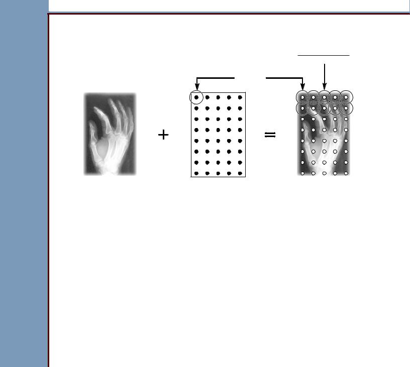
Changing Analog Signals to Digital Signals
pixel code value
(0 - 4095)
SAMPLING
Y
image |
image |
sample |
matrix |
grid |
|
X |
|
analog image |
digital image |
(continual values) |
(discrete values) |
H194_5014HC
Analog signals are changed to digital signals by sampling the blue light from the STORAGE PHOSPHOR SCREEN and moving it through an ANALOG-TO-DIGITAL CONVERTER to make a digital value for the brightness of each sample.
Sampling is similar to making a photograph of the signal at a given time. The sample has both a horizontal and a vertical value. The size of the sample is defined in the system software for both the horizontal and vertical directions.
•The horizontal value indicates a point in time in the motion of the laser beam across the
SCREEN.
•The vertical value indicates a line on the screen at a right angle to the scanning direction.

THEORY GUIDE |
Radiography Theory |
|
|
18JAN08 TG5258-1 Page 24 of 113
If you locate both the horizontal and the vertical points of the sample on an imaginary matrix, similar to the one in the graphic, the result indicates one pixel in the digital image.
Continual analog input values are changed to output values. In this process, the replacement of small ranges of analog input values with one digital output value occurs. The digital output value indicates one pixel of information on the MONITOR.
The output is a linear digital signal. The CLASSIC/ELITE CR SYSTEM emits a 16-bit digital signal with a total signal range of 65,536 levels. Because it is not possible for the human eye to see this range of separate values, the CLASSIC/ELITE CR SYSTEM changes the 16-bit linear image data to 12-bit log data. This 12-bit log provides data from 0 - 4095 values.
These values are used in the CLASSIC/ELITE CR SYSTEM.
Processing the Digital Image
Digital imaging allows users to improve diagnostic images by processing the images. After the digital image is made, the digital data is processed using parameters set up in the software. In the CLASSIC/ELITE CR SYSTEM, this processing occurs in the EXTERNAL PC.
Examples of image processing used for digital images:
•segmentation
•tone scaling
•edge enhancement
•brightness - level
•contrast - window

THEORY GUIDE |
Sequence of Operation |
|
|
18JAN08 TG5258-1 Page 25 of 113
Section 3: Sequence of Operation
Overview of Workflow Using the CLASSIC/ELITE CR SYSTEM
1The Radiology Department receives an exam request.
2The Radiology Technologist (RT) assembles the patient information. Examples of patient information are patient name, ID, and accession number.
 Note
Note
On the CLASSIC/ELITE CR SYSTEM, you can receive patient information through a DICOM-
MODALITY WORKLIST PROVIDER.
3The operator can select network nodes to send the image data.
4The operator uses a CR CASSETTE to do the exam, capturing the latent image on the STORAGE PHOSPHOR SCREEN.
5Using the CLASSIC/ELITE CR SYSTEM or the ROP, the operator enters the CASSETTE
ID Information by scanning the CASSETTE BAR CODE or entering it manually.
6The operator inserts the exposed CASSETTE into the CLASSIC/ELITE CR SYSTEM.
The system scans the SCREEN, capturing the latent image on the SCREEN and changing it to a digital image. After scanning, the SCREEN is automatically erased and inserted into the CASSETTE SHELL.
7The CLASSIC/ELITE CR SYSTEM processes the image. If the system is in:
•“Pass-Through Mode” - the image is automatically sent to all network nodes
•“QA Mode” - the operator can process the image and then send it to other network nodes
8If necessary, the image can be processed and sent to network nodes again.

THEORY GUIDE |
Sequence of Operation |
|
|
18JAN08 TG5258-1 Page 26 of 113
Before Loading the CASSETTE
1After initializing, the CLASSIC/ELITE CR SYSTEM is ready to receive a CASSETTE for scanning. The LOCAL USER INTERFACE (LUI) displays:
•Status ICON: green
•name of the system in white text
2The RT uses a CR CASSETTE to capture the latent image of the body part on the SCREEN.
Status Summary: Ready to Receive a CASSETTE
•CLAMP BAR is in the open position
•PIVOTING PLUSH is in the open position
•LIGHT SEAL BAR is in the open position
•EXTRACTION BAR is at the home position
•HOOKS are in the down position
Loading the CASSETTE
1The RT loads the CASSETTE into the INPUT SLOT until the CASSETTE reaches the CASSETTE ENTRY SENSOR S3.
2The CASSETTE ENTRY SENSOR S3 detects the CASSETTE, and the SLOW SCAN MOTOR moves up to lock the TOP CAP of the EXTRACTION BAR.
3When the CASSETTE is inserted, the INTERNAL BAR CODE READER reads the size, speed, and serial number of the CASSETTE, then:
•emits a sound
•sends information to the IEB BOARD A2:
–“CASSETTE Detected” message
–size of the CASSETTE

THEORY GUIDE |
Sequence of Operation |
|
|
18JAN08 TG5258-1 Page 27 of 113
4When the CASSETTE reaches the CASSETTE EXTRACTION SENSOR S4, the CLAMP
MOTOR closes the CLAMP BAR until the CLAMP CLOSED SENSOR S2 is blocked.
 Note
Note
If the INTERNAL BAR CODE READER did not read the bar code correctly, the operator must enter the data manually at the LUI. The CLAMP MOTOR will not close the CLAMP until the operator enters the size of the CASSETTE.
5The MINI-MCB BOARD A1 sends “CASSETTE Detected” message to the IEB BOARD
A2.
6The IEB BOARD A2 sends a “Scan Request” message to the EXTERNAL PC.
7The EXTERNAL PC:
•checks that it has the quantity of memory necessary to receive an image
•makes a raw image file to receive the image
•sends a “Scan Request Reply” message to the IEB BOARD A2 with a value of “OK”
8The IEB BOARD A2 receives the information about the size and speed of the
CASSETTE.
Status Summary: CASSETTE Loaded
•SLOW SCAN is in the up position
•TOP CAP on the EXTRACTION BAR is locked
•CLAMP BAR is closed
•PLATE remains inside the CASSETTE
•HOOKS on the EXTRACTION BAR are not extended
•bar code was read

THEORY GUIDE |
Sequence of Operation |
|
|
18JAN08 TG5258-1 Page 28 of 113
Removing the PLATE from the CASSETTE
1 The IEB BOARD A2 sends a message to the MINI-MCB BOARD A1 to load the PLATE.
2The SLOW SCAN MOTOR moves down to unlock the TOP CAP, and the HOOKS
MOTOR moves to the “HOOKS in Lane” position.
3The SLOW SCAN MOTOR moves the HOOKS up into the CASSETTE.
4The HOOKS MOTOR moves the HOOKS to the “Unlatch” position.
5The PLATE is “Unlatched” from the CASSETTE, and the SLOW SCAN MOTOR moves the PLATE to the “Start of Scan” position.
6The MINI-MCB BOARD A1 sends a message to the IEB BOARD A2 that the PLATE is loaded.
 Note
Note
If any MOTOR does not move correctly, the MINI-MCB BOARD A1 sends an error message to the IEB BOARD A2.
Status Summary: PLATE Fastened
•CLAMP BARS are holding the CASSETTE
•PLATE is fastened to the EXTRACTION BAR
•EXTRACTION BAR is at the “Start of Scan” position with the fastened PLATE
•PIVOTING PLUSH has made a light-tight environment around the CASSETTE

THEORY GUIDE |
Sequence of Operation |
|
|
18JAN08 TG5258-1 Page 29 of 113
Scanning the SCREEN
1 The IEB BOARD A2:
•actuates the GALVO
•sends a signal to the MINI-MCB BOARD A1 to start the scan, which starts the SLOW
SCAN MOTOR
•sends a signal to the EXTERNAL PC that the scan is starting
2The EXTERNAL PC displays a PROGRESS BAR on the Scan Status screen. This is a graphic display only and not a real-time indication of the status of the scanning operation. The LUI also displays a PROGRESS BAR for the scan status.
3The SLOW SCAN MOTOR rotates, moving the PLATE at a continual speed through the field of scan in the slow scan direction.
4The IEB BOARD A2 controls the motion of the laser beam across the SCREEN in the fast scan direction. The SCREEN is scanned one pixel at a time, one line at a time. See
Scanning the SCREEN - Slow Scan/Fast Scan.
 Note
Note
•The fast scan motion is an almost horizontal trace across the SCREEN, from the back of the SCREEN toward the front. When it reaches the end of a line, it does a fast retrace to start another line. During the scanning, the SCREEN is moving down at a controlled speed to make each fast scan trace one pixel line higher up on the SCREEN than the line before. The result is that the fast scan is in a slightly diagonal trace across the SCREEN.
•The slow scan runs for a determined number of lines in the vertical direction. A set number of samplings occur for each line. The number is determined by the size of the SCREEN. Both the number of lines and the number of samplings are set up in the calibration for that size of SCREEN.
5When the end of the scan is reached, the MINI-MCB BOARD A1 sends a status message to the IEB BOARD A2.
6The IEB BOARD A2 de-energizes the PMTs, GALVO, and the LASER.
7The IEB BOARD A2 sends a “Scan End” message to the EXTERNAL PC. The PROGRESS BAR displays until the image is transferred to the EXTERNAL PC.

THEORY GUIDE |
Sequence of Operation |
|
|
18JAN08 TG5258-1 Page 30 of 113
Erasing the SCREEN
1The IEB BOARD A2 sends an “Erase Plate” command to the MINI-MCB BOARD A1, which sends a signal to the SLOW SCAN to start the erasing operation.
2The SLOW SCAN MOTOR actuates and moves the PLATE into the erase position, determined by the counts of the SLOW SCAN ENCODER.
3The MINI-MCB BOARD A1 energizes the ERASE LAMPS to illuminate for 2 - 16 seconds to remove the image from the SCREEN.
 Note
Note
The length of time the ERASE LAMPS illuminate is determined by the highest pixel code value of the image that was scanned. If one pair of LAMPS is not operating, the time increases by a factor of 2. If more than one pair of LAMPS is not operating, a message displays on the MONITOR.
4When the SCREEN is erased, the MINI-MCB BOARD A1 sends the “Erase Done” status to the IEB BOARD A2.
Loading...