


JLG M4069 Parts Manual


3121825 3369LE/4069LE/M3369/M4069 3

4 3369LE/4069LE/M3369/M4069 3121825

3121825 3369LE/4069LE/M3369/M4069 5


TABLE OF CONTENTS
SECTION 1 - FRAME ........................................................................................................................................................................... 9
FIGURE 1-1. FRAME AND STEERING INSTALLATION - 2WD .................................................................................................... 10
FIGURE 1-2. FRAME AND STEERING INSTALLATION - 4WD .................................................................................................... 12
FIGURE 1-3. DRIVE VALVE ASSEMBLY (4WD ONLY) ................................................................................................................ 14
FIGURE 1-4. REAR AXLE INSTALLATION ................................................................................................................................... 16
FIGURE 1-5. TIRE AND WHEEL DRIVE INSTALLATION ............................................................................................................. 20
FIGURE 1-6. DRIVE HUB ASSEMBLY (USA BUILT MACHINES AND ALL BELGIUM BUILT MACHINES) (Prior to SN
0200174517) .................................................................................................................................................................................. 24
FIGURE 1-7. DRIVE HUB ASSEMBLY (USA BUILT MACHINES) (SN 0200174517 through 0200230091) ................................. 28
FIGURE 1-8. DRIVE MOTOR ASSEMBLY (REAR) ....................................................................................................................... 32
FIGURE 1-9. FRONT DRIVE MOTOR ASSEMBLY (4WD ONLY) ................................................................................................. 34
FIGURE 1-10. YANMAR MOTOR/GENERATOR AND BATTERY CHARGER INSTALLATION (M3369 & M4069 ONLY) ........... 38
FIGURE 1-11. KUBOTA MOTOR/GENERATOR AND BATTERY CHARGER INSTALLATION (M3369 AND M4069 ONLY) ....... 44
FIGURE 1-12. BATTERY CHARGER AND INVERTER INSTALLATIONS (3369LE AND 4069LE ONLY) .................................... 50
FIGURE 1-13. BATTERY CHARGER ASSEMBLY (MAC CHARGER) .......................................................................................... 54
FIGURE 1-14. BATTERY CHARGER ASSEMBLY (DELTA-Q CHARGER) ................................................................................... 56
FIGURE 1-15. INVERTER INSTALLATIONS (3369LE AND 4069LE ONLY) ................................................................................. 58
FIGURE 1-16. ELECTRICAL COMPONENTS INSTALLATIONS (FRAME MOUNTED) ................................................................ 60
FIGURE 1-17. LADDER AND BEACON INSTALLATIONS ............................................................................................................ 62
FIGURE 1-18. LEVELING JACKS INSTALLATION (OPTIONAL) .................................................................................................. 64
FIGURE 1-19. COVERS INSTALLATION (FRAME MOUNTED).................................................................................................... 68
SECTION 2 - GROUND CONTROLS ................................................................................................................................................ 71
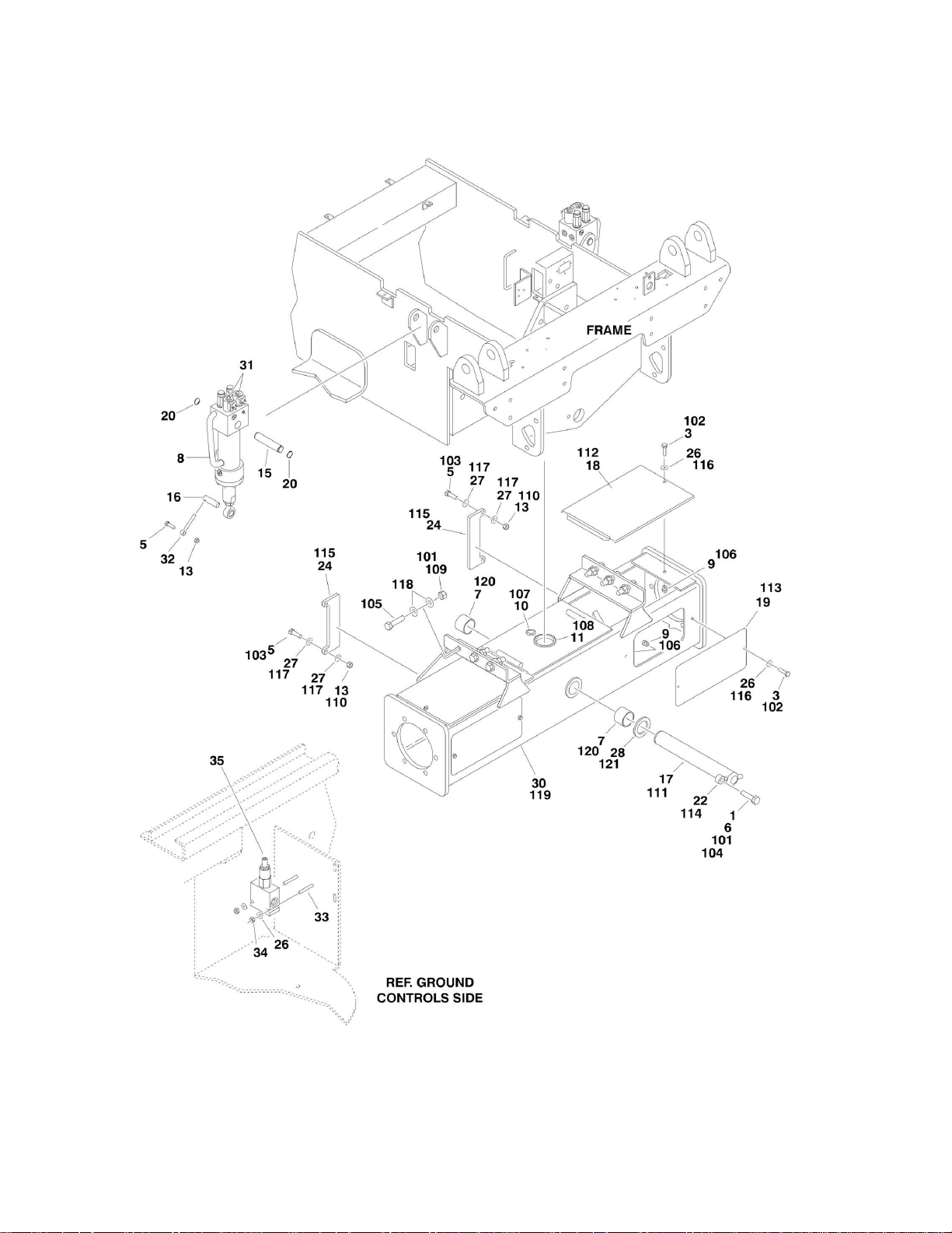
FIGURE 2-1. RIGHT SIDE COMPONENTS INSTALLATION ........................................................................................................ 72
FIGURE 2-2. MAIN CONTROL VALVE ASSEMBLY ...................................................................................................................... 76
FIGURE 2-3. GROUND CONTROL BOX ASSEMBLY ................................................................................................................... 78
FIGURE 2-4. LEFT SIDE COMPONENTS INSTALLATION ........................................................................................................... 82
FIGURE 2-5. PUMP ASSEMBLY ................................................................................................................................................... 84
FIGURE 2-6. BATTERY BOX INSTALLATIONS ............................................................................................................................ 86
SECTION 3 - SCISSORS ARMS ....................................................................................................................................................... 89
FIGURE 3-1. SCISSORS ARMS INSTALLATION - 3369LE AND M3369 (USA BUILT MACHINES AND ALL BELGIUM BUILT
MACHINES) (Prior to SN 0200152398) .......................................................................................................................................... 90
FIGURE 3-2. SCISSORS ARMS INSTALLATION - 3369LE AND M3369 (USA BUILT MACHINES) (SN 0200152398 through
0200230091) .................................................................................................................................................................................. 94
FIGURE 3-3. SCISSORS ARMS INSTALLATION - 4069LE & M4069 (USA BUILT MACHINES AND ALL BELGIUM BUILT
MACHINES) (Prior to SN 0200152398) .......................................................................................................................................... 98
FIGURE 3-4. SCISSORS ARMS INSTALLATION - 4069LE AND M4069 (USA BUILT MACHINES) (SN 0200152398 through
0200230091) ................................................................................................................................................................................ 102
FIGURE 3-5. SCISSORS GUARDS INSTALLATION ................................................................................................................... 106
SECTION 4 - PLATFORM ................................................................................................................................................................ 109
FIGURE 4-1. PLATFORM AND ACCESSORIES INSTALLATION ............................................................................................... 110
FIGURE 4-2. FOLDDOWN HANDRAILS AND EXTENSION INSTALLATION (MANUALLY OPERATED PLATFORM) ............. 114
FIGURE 4-3. PLATFORM CONSOLE BOX ASSEMBLY ............................................................................................................. 118
FIGURE 4-4. DRIVE/STEER CONTROLLER ASSEMBLY (Prior to SN 0200142020, SN 1200000100 through 0200230091) .. 122
FIGURE 4-5. DRIVE/STEER CONTROLLER ASSEMBLY (SN 0200142020 through 0200230091) ........................................... 124
SECTION 5 - CYLINDER ................................................................................................................................................................. 127
FIGURE 5-1. AXLE LOCKOUT CYLINDER ASSEMBLY ............................................................................................................. 128
FIGURE 5-2. LEVELING JACK CYLINDER ASSEMBLY (USA BUILT MACHINES) (Prior to SN 0200104829) .......................... 130
FIGURE 5-3. LEVELING JACK CYLINDER ASSEMBLY (SN 0200104829 through 0200112734, SN 1200000100 through
0200230091) ................................................................................................................................................................................ 132
FIGURE 5-4. LEVELING JACK CYLINDER ASSEMBLY (USA BUILT MACHINES) (ORIGINAL EQUIPMENT) (SN 0200112735
through 0200214444) ................................................................................................................................................................... 134
FIGURE 5-5. LEVELING JACK CYLINDER ASSEMBLY (USA BUILT MACHINES) (SERVICE REPLACEMENT) (SN
0200214444 through 0200230091)............................................................................................................................................... 136
FIGURE 5-6. LIFT CYLINDER COMPONENTS ASSEMBLY - 3369LE & M3369 ........................................................................ 138
FIGURE 5-7. LIFT CYLINDER COMPONENTS ASSEMBLY - 4069LE AND M4069 ................................................................... 142
FIGURE 5-8. STEER CYLINDER ASSEMBLY ............................................................................................................................. 146
3121825 3369LE/4069LE/M3369/M4069 7

TABLE OF CONTENTS
SECTION 6 - HYDRAULIC ............................................................................................................................................................... 149
FIGURE 6-1. HYDRAULIC DIAGRAM - FIXED AXLE .................................................................................................................. 150
FIGURE 6-2. HYDRAULIC DIAGRAM - OSCILLATING AXLE ..................................................................................................... 152
FIGURE 6-3. HYDRAULIC DIAGRAM - 4WD (OPTIONAL) .......................................................................................................... 156
FIGURE 6-4. HYDRAULIC DIAGRAM - LEVELING JACKS (OPTIONAL) .................................................................................... 158
FIGURE 6-5. HYDRAULIC DIAGRAM LIST .................................................................................................................................. 160
SECTION 7 - ELECTRICAL .............................................................................................................................................................. 161
FIGURE 7-1. ELECTRICAL SCHEMATIC .................................................................................................................................... 162
FIGURE 7-2. STANDARD ELECTRICAL COMPONENTS INSTALLATION (WITH MAC CHARGER)......................................... 164
FIGURE 7-3. STANDARD ELECTRICAL COMPONENTS INSTALLATION (WITH DELTA-Q CHARGER) ................................. 172
FIGURE 7-4. OPTIONAL ELECTRICAL COMPONENTS INSTALLATION .................................................................................. 178
SECTION 8 - DECALS ..................................................................................................................................................................... 185
FIGURE 8-1. DECAL INSTALLATION (USA BUILT MACHINES AND ALL BELGIUM BUILT MACHINES) (Prior to SN
0200150261) ................................................................................................................................................................................. 186
FIGURE 8-2. DECAL INSTALLATION (USA BUILT MACHINES) (SN 0200150261 through 0200230091) ................................. 192
SECTION 9 - RECOMMENDED SERVICE PARTS STOCK ............................................................................................................ 195
FIGURE 9-1. MODELS 3369LE/M3369/4069LE/M4069 STANDARD PARTS ............................................................................. 196
FIGURE 9-2. MODELS 3369LE/M3369/4069LE/M4069 VARIABLE PARTS ................................................................................ 198
SECTION 10 - SPECIAL OPTIONS ................................................................................................................................................. 199
FIGURE 10-1. SPECIAL OPTIONS .............................................................................................................................................. 200
PART NUMBER INDEX .................................................................................................................................................................... 203
8 3369LE/4069LE/M3369/M4069 3121825

SECTION 1 - FRAME
SECTION 1 - FRAME
3121825 3369LE/4069LE/M3369/M4069 9

SECTION 1 - FRAME
FIGURE 1-1. FRAME AND STEERING INSTALLATION - 2WD
10 3369LE/4069LE/M3369/M4069 3121825

SECTION 1 - FRAME
ITEM
PART NUMBER
QTY
DESCRIPTION
REV
0270519
Ref
STEERING AND SPINDLES INSTALLATIONS
F 1 0440162
2
Bearing, Thrust
2 0440247
1
Bearing
4
1683994
1
Steer Cylinder Assembly (See CYLINDER SECTION for
Breakdown)
5
2780234
2
Hub/Spindle Assembly (See Items 101-115 for Breakdown)
6 3300240
4
Locknut 5/8in-18NC
7 3313003
2
Nut, Slotted 1-1/4in-7NC
8 3422897
2
Kingpin 9
3450812
2
Pin, Cotter 1/4in x 3in
10
3900266
4
Screw, Shoulder
11
4712200
16
Flatwasher 3/4in Thin
12
4713000
2
Flatwasher 1-1/4in Thin
13
4846301
1
Tie-Rod
2780234
Ref
HUB/SPINDLE ASSEMBLY
D
101
7020033
2
Cap, Dust (1 per Assembly)
102
0961951
4
Bushing, Garmax (2 Per Assembly)
103
0962140
4
Bearing, Garmax (2 per Assembly)
104
7020035
2
Hub (1 Per Assembly)
105
7020036
2
Cup, Bearing (Inner) (1 per Assembly)
106
7020037
2
Cone, Bearing (Inner) (1 per Assembly)
107
7020038
2
Cup, Bearing (Outer) (1 per Assembly)
108
7020039
2
Cone, Bearing (Outer) (1 per Assembly)
109
7020148
2
Spindle (1 per Assembly)
110
7020140
2
Pin, Cotter (1 per Assembly)
111
7020040
2
Seal (1 Per Assembly)
112
7020054
2
Nut, Castle 1-1/4in-12 (1 per Assembly)
113
7020041
18
Stud 5/8in-18NF (9 per Assembly)
114
7020042
18
Lugnut 5/8in-18NF (9 per Assembly)
115
7020055
2
Washer, Tanged 1-1/4in (1 per Assembly)
FIGURE 1-1. FRAME AND STEERING INSTALLATION - 2WD
3121825 3369LE/4069LE/M3369/M4069 11

SECTION 1 - FRAME
FIGURE 1-2. FRAME AND STEERING INSTALLATION - 4WD
12 3369LE/4069LE/M3369/M4069 3121825

SECTION 1 - FRAME
ITEM
PART NUMBER
QTY
DESCRIPTION
REV
0270992
Ref
STEERING INSTALLATIONS
H 1 0100011
AR
Compound, Locking
3 0440162
4
Bearing, Thrust
4 0440247
1
Bearing 5
0630549
8
Bolt 3/8in-16NC x 1 1/4in
6 0641406
4
Bolt 1/4in-20NC x 3/4in
7 0641418
4
Bolt 1/4in-20NC x 2 1/4in
8 0641506
4
5/16in-18NC x 3/4in
9 0641610
4
Bolt 3/8in-16NC x1 1/4in
11
0902704
2
Bracket, Clamp Mounting
12
0961951
4
Bushing, Composite
13
0962140
3
Bushing, Composite
14
1320095
4
Clamp 15
1320285
2
Clamp (Top)
16
1320286
2
Clamp (Bottom)
17
1683994
1
Steer Cylinder Assembly (See CYLINDER SECTION for
Breakdown)
21
3300240
4
Locknut
22
3311405
8
Locknut 1/4in-20NC
23
3311605
4
Locknut 3/8in-16NC
24
3313003
2
Nut, Slotted 1 1/4in-7NC
25
3422897
2
Kingpin
26
3450812
2
Pin, Cotter 1/4in x 3in
27
3572850
1
Plate, Valve Mounting
28
3900266
4
Screw, Shoulder
29
1001097815
2
Spindle (was p/n 4130386)
30
4711400
12
Flatwasher 1/4in Narrow
31
4712200
16
Flatwasher 3/4in Narrow
32
4713000
2
Flatwasher 1 1/4in Narrow
33
4751600
6
Flatwasher 3/8in
34
4846301
1
Tie-Rod
35 Ref
Harness, Front Wheel Assist Options (Not Shown - See
ELECTRICAL SECTION for Breakdown):
35
4922551
1
Harness USA Built Machines (Prior to SN 0200196451)
35
1001101989
1
Harness USA Built Machines (SN 0200196451 through
0200230091)
35
4922551
1
Harness Belgium Built Machines
36
1704998
2
Decal - All Wheel Drive (Not Shown - Located on Platform)
0270991
Ref
VALVES INSTALLATIONS
D
113
Ref
Valve Assembly - Drive (See DRIVE VALVE ASSEMBLY (4WD
ONLY) for Breakdown)
113
4641127
NLA
USA Built Machines (use p/n 1001092586) (Prior to SN
0200156383)
113
1001092586
1
USA Built Machines (SN 0200156383 through 0200230091)
113
4641127
NLA
Belgium Built Machines (use p/n 1001092586) (SN 0200156383
to Present)
114
4641148
1
Flow Divider Assembly
114
Not Available
Seal Kit - 4641148 Valve
FIGURE 1-2. FRAME AND STEERING INSTALLATION - 4WD
3121825 3369LE/4069LE/M3369/M4069 13

SECTION 1 - FRAME
FIGURE 1-3. DRIVE VALVE ASSEMBLY (4WD ONLY)
14 3369LE/4069LE/M3369/M4069 3121825

SECTION 1 - FRAME
ITEM
PART NUMBER
QTY
DESCRIPTION
REV
Ref
DRIVE VALVE ASSEMBLY
4641127
Ref
USA Built Machines (Prior to SN 0200156383)
D 1001092586
Ref
USA Built Machines (SN 0200156383 through 0200230091)
A 4641127
Ref
Belgium Built Machines
D
Ref
Note: Original Equipment p/n 4641127 may have been
replaced with Service Replacement p/n 1001092586. Identify
p/n stamped on valve block before ordering parts.
2 Ref
Manifold Options:
2 Not Available
Manifold p/n 4641127 Valve
2 1001092586
1
Manifold p/n 1001092586 Valve
3 Ref
Control Valve Assembly
3 7024011
1
Control Valve p/n 4641127 Valve
3 70001422
1
Control Valve p/n 1001092586 Valve
3 7012773
1
Seal Kit
3A
7021375
2
Nut
3B Ref
Coil
3B
7024013
2
Coil p/n 4641127 Valve
3B
70002947
2
Coil p/n 1001092586 Valve
4 Ref
Control Valve Assembly
4 7024011
1
Control Valve Assembly p/n 4641127 Valve
4 70001422
1
Control Valve Assembly p/n 1001092586 Valve
4 7012773
1
Seal Kit
4A
7021375
2
Nut
4B Ref
Coil
4B
7024013
2
Coil p/n 4641127 Valve
4B
70002947
2
Coil p/n 1001092586 Valve
5 4641129
1
Cartridge, Check
5 7012540
1
Seal Kit - 4641129 Valve
6 4641129
1
Cartridge, Check
6 7012540
1
Seal Kit - 4641129 Valve
7 4641129
1
Cartridge, Check
7 7012540
1
Seal Kit - 4641129 Valve
8 4641129
1
Cartridge, Check
8 7012540
1
Seal Kit - 4641129 Valve
9 7018942
8
Capscrew #10-24NC x 2in
FIGURE 1-3. DRIVE VALVE ASSEMBLY (4WD ONLY)
3121825 3369LE/4069LE/M3369/M4069 15
SECTION 1 - FRAME
FIGURE 1-4. REAR AXLE INSTALLATION
16 3369LE/4069LE/M3369/M4069 3121825

FIGURE 1-4. REAR AXLE INSTALLATION
ITEM
PART NUMBER
QTY
DESCRIPTION
REV
0270533
Ref
OSCILLATING AXLE INSTALLATION
K 1 0100011
AR
Compound, Locking
3 0641408
6
Bolt 1/4in-20NC x 1in
5 0641610
6
Bolt 3/8in-16NC x 1-1/4in
6 0642012
1
Bolt 5/8in-11NC x 1-1/2in
7 0961950
2
Bushing
8
1684064
2
Oscillating Axle Cylinder Assembly (See CYLINDER SECTION for
Breakdown)
9
2080061
6
Fastener, Insert
10
2540038
1
Grommet
11
2540039
1
Grommet
13
3311605
6
Locknut 3/8in-16NC
15
3422745
2
Pin (Top)
16
3422899
2
Pin (Bottom)
17
3422900
1
Pin, Axle Pivot
18
3572553
2
Cover (Top)
19
3572554
2
Cover (Side)
20
3760115
4
Ring, Retaining
22
3841258
1
Keeper, Pin
24
4071008
2
Shim 26
4711400
8
Flatwasher 1/4in Narrow
27
4711600
8
Flatwasher 3/8in Narrow
28
4740158
1
Thrustwasher
30
4846299
1
Axle Weldment
31
4641173
4
Solenoid Valve Assembly
31
70000898
4
Cartridge, Solenoid Valve
31
7024502
4
Seal Kit - 70000898 Valve (1 per Valve)
31
7024501
4
Coil (1 per Valve)
32
3841143
2
Keeper, Pin
33
0641416
4
Bolt 1/4in-20NC x 2in
34
3311405
4
Locknut 1/4in-20NC
35
4641182
1
Valve, Pressure Reducing
35
7021661
1
Seal Kit - 4641182 Valve
0270568
Ref
FIXED AXLE INSTALLATION
B
101
0100011
AR
Compound, Locking
102
0641408
6
Bolt 1/4in-20NC x 1in
103
0641610
4
Bolt 3/8in-16NC x 1-1/4in
104
0642012
1
Bolt 5/8in-11NC x 1-1/2in
105
0682020
6
Bolt 5/8in-11NC x 2-1/2in (Grade 8)
106
2080061
6
Fastener, Insert
107
2540038
1
Grommet
108
2540039
1
Grommet
109
3272001
6
Nut 5/8in-11NC (Grade 8)
110
3311605
4
Locknut 3/8in-16NC
111
3422900
1
Pin, Axle Pivot
112
3572553
2
Cover (Top)
113
3572554
2
Cover (Side)
114
3841258
1
Keeper, Pin
115
4071008
2
Shim 116
4711400
14
Flatwasher 1/4in Narrow
SECTION 1 - FRAME
3121825 3369LE/4069LE/M3369/M4069 17

ITEM
PART NUMBER
QTY
DESCRIPTION
REV
117
4711600
8
Flatwasher 3/8in Narrow
118
4712000
12
Flatwasher 5/8in Narrow
119
4846333
1
Axle Weldment
120
0961950
2
Bushing
121
4740158
1
Thrustwasher
SECTION 1 - FRAME
18 3369LE/4069LE/M3369/M4069 3121825


SECTION 1 - FRAME
FIGURE 1-5. TIRE AND WHEEL DRIVE INSTALLATION
20 3369LE/4069LE/M3369/M4069 3121825

SECTION 1 - FRAME
ITEM
PART NUMBER
QTY
DESCRIPTION
REV
Ref
REAR WHEEL DRIVE INSTALLATIONS
0270473
Ref
USA Built Machines (Prior to SN 0200174517)
H 1001099375
Ref
USA Built Machines (SN 0200174517 through 0200230091)
A 0270473
Ref
Belgium Built Machines
H 1 0100019
AR
Compound, Locking
7 0641609
8
Bolt 3/8in-16NC x 1-1/8in
8 0641826
4
Bolt 1/2in-13NC x 3-1/4in
9 Ref
Bolt Options:
9 0682011
12
Bolt 5/8in-11NC x 1-3/8in (Grade 8)
9 0682012
12
Bolt 5/8in-11NC x 1-1/2in (Grade 8)
11
0920118
2
Drive Brake Assembly
B
11
Not Available
1
Ring, Sensor (was p/n 7027275 which is No Longer Available.
Replace Complete Brake)
11
7007977
2
Ring, Bearing Retaining (Large) (1 per Assembly)
11
7011716
2
Ring, Bearing Retaining (Small) (1 per Assembly)
11
7007913
4
Bolt
11
7011757
2
Complete Repair Kit (Includes Case and Oil Seals, O-Rings,
Back-up Rings, Stator and Rotor Discs, Return Plate, Springs,
Bearing and Brake to Hub Gasket) (1 per Assembly)
11
2900768
2
Bearing Kit (1 per Assembly)
11
7007900
2
Seal, Oil - Front (1 per Assembly)
11
7007933
2
Gasket, Brake to Hub (1 Per Assembly)
11
70002408
2
Gasket, Brake to Motor (1 Per Assembly) (Not Included in
Repair Kit)
21 Ref
Drive Hub Assembly Options:
21
2780236
2
USA Built Machines (See DRIVE HUB ASSEMBLY (USA
BUILT MACHINES AND ALL BELGIUM BUILT MACHINES) for
Breakdown) (Prior to SN 0200174517)
21
2780282
2
USA Built Machines (See DRIVE HUB ASSEMBLY (USA
BUILT MACHINES) for Breakdown) (SN 0200174517 through
0200230091)
21
2780236
2
Belgium Built Machines (See DRIVE HUB ASSEMBLY (USA
BUILT MACHINES AND ALL BELGIUM BUILT MACHINES) for
Breakdown)
22
3020008
AR
Lubricant, Mobilube HD 80W-90 (Not Shown)
23
3160256
2
Drive Motor Assembly (See DRIVE MOTOR ASSEMBLY (REAR)
for Breakdown)
30
4711600
8
Flatwasher 3/8in Narrow
32
4892000
12
Washer, Hardened 5/8in
33
3020037
AR
Grease, Coupling
0270992
Ref
FRONT WHEEL DRIVE INSTALLATION (4WD ONLY)
H
101
0100019
AR
Compound, Locking
110
0681809
20
Bolt 1/2in-13NC x 1-1/8in
118
2780260
2
Drive Hub Assembly
118A
4300145
18
Bolt, Wheel (9 per Hub)
119
3160245
1
Drive Motor Assembly (Right Side) (See FRONT DRIVE MOTOR
ASSEMBLY (4WD ONLY) for Breakdown)
120
Ref
Drive Motor Assembly (Left Side) Options (See FRONT DRIVE
MOTOR ASSEMBLY (4WD ONLY) for Breakdown)
120
3160267
1
USA Built Machines (Prior to SN 0200196451)
120
1001101934
1
USA Built Machines (SN 0200196451 through 0200230091)
120
3160267
1
Belgium Built Machines
FIGURE 1-5. TIRE AND WHEEL DRIVE INSTALLATION
3121825 3369LE/4069LE/M3369/M4069 21

ITEM
PART NUMBER
QTY
DESCRIPTION
REV
Ref
TIRE AND WHEEL INSTALLATIONS
0270570
Ref
IN240/55 x17.5 (Foam-Filled Tire with JLG in Tread Pattern)
B
0270581
Ref
IN240/55 x 17.5 (Non-Marking Foam-Filled Tire with JLG in
Tread Pattern) (Prior to SN 0200114833)
A
0273477
Ref
IN240/55 x 17.5 (Non-Marking Foam-Filled Tire with Lightning
in Tread Pattern) (SN 0200114833 through 0200230091)
A
0270523
NLA
240/55 x D17.5 R4 Tread (Non-Marking Foam-Filled All Lug
Tire) (4069LE/M3369/M4069 Only) (No Longer Used - Use p/n
0273477 as Replacement)
D
0271690
NLA
240/55 x D17.5 R4 Tread (Non-Marking Foam-Filled All Lug
Tire) (3369LE Only) (No Longer Used - Use p/n 0273477 as
Replacement)
C
0270627
Ref
27.2/10.5LL - 15.0 (Turf Tire)
B
201
Ref
Tire and Wheel Assembly Options:
201
0258997
4
IN240/55 x17.5 (Foam-Filled - See Note) (JLG in Tread Pattern)
1-B
201
0270417
4
IN240/55 x 17.5 (Non-Marking Foam-Filled - See Note) (JLG in
Tread Pattern) (Prior to SN 0200114833)
2-B
201
0273468
4
IN240/55 x 17.5 (Non-Marking Foam-Filled - See Note)
(Lightning Tread Pattern) (SN 0200114833 through
0200230091)
D
201
0271948
NLA
240/55 x D17.5 R4 Tread (Left Side) (Non-Marking Foam-Filled
All Lug Tire) (Use p/n 0273468) (See Assembly Note Also)
201
0271949
NLA
240/55 x D17.5 R4 Tread (Right Side) (Non-Marking FoamFilled Tire All Lug Tire) (Use p/n 0273468) (See Assembly Note
Also)
201
0270530
4
27.2/10.5LL - 15.0 (Turf Tire)
D
Ref
Note: Assemblies may require ballast/foam filling to
manufacturer's specification prior to installing on a machine.
Refer to Operation and Safety or Service and Maintenance
Manuals. Purchase individual tire and/or rim only if able to
foam fill tire and wheel assembly, otherwise, purchase
complete assembly.
201A
Ref
Tire Options (See Note):
201A
4520209
4
IN240/55 x17.5 (JLG in Tread Pattern)
201A
4520247
4
IN240/55 x 17.5 (Non-Marking Foam-Filled Tire with JLG in
Tread Pattern) (Prior to SN 0200114833)
201A
4520269
4
IN240/55 x 17.5 (Non-Marking Foam-Filled Tire with
Lightning Tread Pattern (SN 0200114833 through
0200230091)
201A
4520260
NLA
240/55 x D17.5 R4 Tread (Non-Marking Foam-Filled All Lug
Tire) (Use p/n 0273468)
201A
4520249
4
27.2/10.5LL - 15.0 (Turf Tire)
201B
Ref
Valve, Air Options:
201B
4640392
4
Valve (0258997, 0270417 & 0273477 Installations)
201B
4640113
4
Valve (0270523, 0270627 & 0271690 Installations)
201C
Ref
Rim, Wheel Options (See Note):
201C
4860222
4
6.75 x 17.5
201C
4860191
4
6.812 x 17.5
201C
4860221
4
8.0 x 15.0
202
3300426
36
Lugnut
SECTION 1 - FRAME
22 3369LE/4069LE/M3369/M4069 3121825


SECTION 1 - FRAME
FIGURE 1-6. DRIVE HUB ASSEMBLY (USA BUILT MACHINES AND ALL BELGIUM BUILT MACHINES)
(Prior to SN 0200174517)
24 3369LE/4069LE/M3369/M4069 3121825

SECTION 1 - FRAME
ITEM
PART NUMBER
QTY
DESCRIPTION
REV
2780236
Ref
DRIVE HUB ASSEMBLY
D 1 7021323
4
Gear, Planet
2 7021324
3
Gear, Planet
3 7021325
1
Gear, Sun
4 7023803
1
Nut, Shaft
Ref
NOTE: Unless there is capability to torque shaft nut (item 4) to
625 ft/lbs (850Nm) Repair beyond this level is NOT advised.
5
7021326
3
Bolt, Planet
6 7021327
1
Ring, Support
7 7021328
1
Carrier, Planet
8 70003711
1
Cover 10
70003712
3
Bearing, Roller
11
70003713
4
Bearing, Roller
12
70003714
2
Bearing, Roller
14
70003715
3
Ring, Retaining
15
70003716
4
Ring, Retaining
16
7021341
1
Ring, Retaining
17
70003717
3
Disk, Support
19
See Note
1
O-Ring (Note: Use Items 300 & 303)
20
See Note
1
Seal, Ring (Note: Use Items 300 & 303)
21
See Note
3
Plug (Note: Use Items 300 & 303)
22
See Note
3
Seal, Ring (Note: Use Items 300 & 303)
23
7021342
3
Bolt 29
7024049
1
Washer, Housing
30
7021335
1
Gear, Ring
33
See Note
1
O-Ring (Note: Use Items 300, 303 & 304)
34
70003718
1
Ring, Retaining
43
7021336
1
Shaft, Sun Gear
44
7021337
1
Shaft, Input
49
7024051
1
Thrustwasher
51
70003719
1
Cover 52
70003720
1
Disk 53
70003721
2
Bolt 54
See Note
1
O-Ring (Note: Use Items 300, 304, 305 & 306)
55
7024053
1
Spring, Pressure
56
70003722
1
Rod, Shaft
59
70003723
1
Disk, Rotor
60
7021339
1
Spindle
62
7021340
1
Coupler
66
70003724
1
Ring, Retaining
81
7024983
1
Bearing, Ball
82
7021341
2
Ring, Retaining
83
7024931
1
Ring, Retaining
88
7021344
9
Stud, Wheel (was p/n 7024984)
99
7024985
1
Plug 224
Ref
Component Options:
224
See Note
2
Ball (Note: Not Available - Use Slotted Pin in Item 303) (Prior to
SN 0200141266)
224
See Note
2
Expander (Note: Not Available - Use Slotted Pin in Item 303)
FIGURE 1-6. DRIVE HUB ASSEMBLY (USA BUILT MACHINES AND ALL BELGIUM BUILT MACHINES)
(Prior to SN 0200174517)
3121825 3369LE/4069LE/M3369/M4069 25

ITEM
PART NUMBER
QTY
DESCRIPTION
REV
(Prior to SN 0200141266)
224
See Note
2
Plug (Note: Not Available - Use Slotted Pin in Item 303) (Prior to
SN 0200141266)
224
70003725
2
Pin, Slotted (SN 0200141266 through 0200230091)
Ref
KIT OPTIONS:
Ref
Seal Kit Options:
300
7021333
1
Seal Kit (Includes Items 19-22, 33 & 54)
Ref
Repair Kit Options:
301
7024981
1
Planet Gear Kit 1 (Includes Items 1, 11 & 15)
302
7024986
1
Planet Gear Kit 2 (Includes Items 2, 10,14 & 17)
303
7024047
1
Bearing Kit (Includes Items 4, 12, 19, 20, 23, 33 & 224)
Ref
NOTE: Unless there is capability to torque shaft nut (item
4) to 625 ft/lbs (850Nm) Repair beyond this level is NOT
advised.
304
7021329
1
Cover Kit (Includes Items 8, 21, 22, 33, 34 & 51-54)
305
7021338
1
Mechanical Disconnect Kit 1(Includes Items 54-56, 59 & 66)
306
7024054
1
Mechanical Disconnect Kit 2 (Includes Items 51, 53, 54 & 56)
SECTION 1 - FRAME
26 3369LE/4069LE/M3369/M4069 3121825


SECTION 1 - FRAME
FIGURE 1-7. DRIVE HUB ASSEMBLY (USA BUILT MACHINES) (SN 0200174517 through 0200230091)
28 3369LE/4069LE/M3369/M4069 3121825

SECTION 1 - FRAME
ITEM
PART NUMBER
QTY
DESCRIPTION
REV
2780282
Ref
DRIVE HUB ASSEMBLY
B 1 70001366
1
Carrier, Sub Assembly
1A
See Note
3
Shaft, Planet (Note: use p/n 70001366)
1B
See Note
1
Carrier (Note: use p/n 70001366)
1C
See Note
3
Gear, Planet (Note: use p/n 70001366)
1D
See Note
42
Bearing, Needle (Note: use p/n 70001366)
1E
See Note
3
Pin, Roll (Note: use p/n 70001366)
1F
See Note
6
Thrustwasher (Note: use p/n 70001366)
2 70001367
1
Carrier, Input
2A
See Note
3
Shaft, Planet (Note: use p/n 70001367)
2B
See Note
1
Carrier (Note: use p/n 70001367)
2C
See Note
3
Gear, Planet (Note: use p/n 70001367)
2D
See Note
84
Bearing, Needle (Note: use p/n 70001367)
2E
See Note
3
Spacer, Thrust (Note: use p/n 70001367)
2F
See Note
3
Pin, Roll (Note: use p/n 70001367)
2G
See Note
12
Thrustwasher (Note: use p/n 70001367)
2H
See Note
1
Thrustwasher (Note: use p/n 70001367)
3 See Note
1
Cover (Note: use p/n 70001368)
4 70001369
1
Shaft, Input
5 70001370
1
Coupling
6 70001371
1
Shaft, Sun Gear
7 70001372
1
Spindle 8
70001373
1
Gear, Ring
9 See Note
NSS
Housing (Note: Not Available - Purchase Complete Assembly)
10
See Note
1
Bearing, Tapered-Cone (Note: use p/n 7017007)
11
See Note
2
Bearing, Tapered-Cup (Note: use p/n 7017007)
12
See Note
1
Bearing, Tapered-Cone (Note: use p/n 7017007)
13
7017009
1
Thrustwasher
15
Item 102
1
Seal, Lip
16
70001374
1
Spring 17
70001375
1
Ring, Retaining (Internal)
18
See Note
1
Ring, Retaining (External) (Note: use p/n 70001380)
19
7024738
1
Ring, Retaining (Internal)
20
70001376
1
Ring, Retaining (External)
21
70001377
1
Ring, Retaining (External)
22
7000281
4
Screw (Not Shown - ID plate screws)
23
7017022
3
Bolt, Flathead (Not Shown - Located on front of hub)
24
See Note
1
O-Ring (Note: use p/n 70001380)
25
See Note
1
O-Ring (Note: use p/n 70001380)
26
70001378
1
Spacer, Thrust
27
70001379
1
Thrustwasher
28
7024741
1
Spacer, Thrust
29
7007640
9
Stud, Wheel
30
See Note
1
Flange, Plate (Note: use p/n 70001368)
31
See Note
1
Cap, Disengage (Note: use p/n 70001368)
32
See Note
1
Pin, Dowel (Note: use p/n 70001368)
33
See Note
2
Bolt (Note: use p/n 70001368)
34
See Note
1
O-Ring (Note: use p/n 70001368)
35
See Note
1
O-Ring (Note: use p/n 70001368)
36
See Note
1
Plug (Note: use p/n 70001368)
FIGURE 1-7. DRIVE HUB ASSEMBLY (USA BUILT MACHINES) (SN 0200174517 through 0200230091)
3121825 3369LE/4069LE/M3369/M4069 29

ITEM
PART NUMBER
QTY
DESCRIPTION
REV
Ref
KIT OPTIONS
101
7017007
1
Planet Gear Bearing Kit (Includes Items 10-12)
102
70001380
1
Planet Gear Seal Kit (Includes Items 15, 18, 24 & 25)
103
70001368
1
Cap/Disengage Kit (Includes Items 3 & 30-36)
SECTION 1 - FRAME
30 3369LE/4069LE/M3369/M4069 3121825
 Loading...