


 Loading...
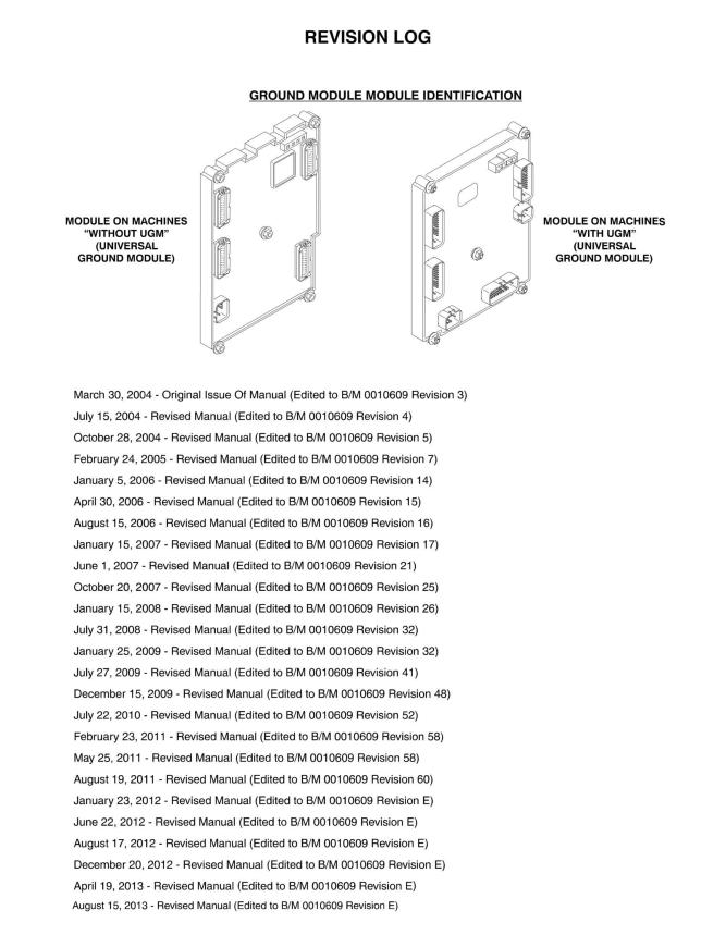
3121172 |
1250AJP |
3 |

4 |
1250AJP |
3121172 |
3121172 |
1250AJP |
5 |

6 |
1250AJP |
3121172 |
|
TABLE OF CONTENTS |
|
SECTION 1 - FRAME........................................................................................................................................................................... |
|
9 |
FIGURE 1-1. AXLE INSTALLATIONS ............................................................................................................................................ |
|
10 |
FIGURE 1-2. STEER INSTALLATION............................................................................................................................................ |
|
14 |
FIGURE 1-3. TIRE AND WHEEL DRIVE INSTALLATION ............................................................................................................. |
|
16 |
FIGURE 1-4. DRIVE HUB ASSEMBLY (Prior to SN 0300079667) ................................................................................................ |
20 |
|
FIGURE 1-5. DRIVE MOTOR ASSEMBLY (Prior to SN 0300079667)........................................................................................... |
24 |
|
FIGURE 1-6. HUB AND MOTOR ASSEMBLY (SN 0300079667 through 0300083555) ................................................................ |
26 |
|
FIGURE 1-7. HUB AND MOTOR ASSEMBLY (SN 0300083556 through 0300103906) ................................................................ |
32 |
|
FIGURE 1-8. DRIVE HUB ASSEMBLY - BONFIGLIOLI (SN 0300103907 to Present) .................................................................. |
36 |
|
FIGURE 1-9. DRIVE HUB ASSEMBLY - REGGIANA RIDUTTORI (SN 0300103907 to Present) ................................................. |
40 |
|
FIGURE 1-10. DRIVE MOTOR ASSEMBLY (SN 0300103907 to Present) .................................................................................... |
44 |
|
FIGURE 1-11. FRAME VALVES AND COVERS INSTALLATION ................................................................................................. |
46 |
|
FIGURE 1-12. TRACTION VALVE ASSEMBLY (Prior to SN 0300103907) ................................................................................... |
50 |
|
FIGURE 1-13. TRACTION VALVE ASSEMBLY (SN 0300103907 to Present) .............................................................................. |
52 |
|
SECTION 2 - TURNTABLE................................................................................................................................................................ |
|
55 |
FIGURE 2-1. VALVE, BATTERY, HORN AND AUXILIARY PUMP INSTALLATIONS ................................................................... |
56 |
|
FIGURE 2-2. MAIN VALVE ASSEMBLY ........................................................................................................................................ |
|
62 |
FIGURE 2-3. TURNTABLE SWING DRIVE AND BEARING INSTALLATION................................................................................ |
66 |
|
FIGURE 2-4. SWING MOTOR/HUB ASSEMBLY........................................................................................................................... |
|
68 |
FIGURE 2-5. CATERPILLAR DIESEL ENGINE INSTALLATION................................................................................................... |
74 |
|
FIGURE 2-6. DEUTZ BF4M2011 TIER II AND TD2011 TIER III/IVI ENGINE INSTALLATIONS ................................................... |
82 |
|
FIGURE 2-7. DEUTZ TD2011 TIER IVI FLEX AND TIER IVI-PRE ENGINE INSTALLATION ....................................................... |
92 |
|
FIGURE 2-8. DEUTZ TCD2.9L4 ENGINE INSTALLATIONS ....................................................................................................... |
|
100 |
FIGURE 2-9. PUMP ASSEMBLY (REXROTH) (CATERPILLAR ENGINE MACHINES) .............................................................. |
112 |
|
FIGURE 2-10. PUMP ASSEMBLY (REXROTH) (DEUTZ ENGINE MACHINES)......................................................................... |
118 |
|
FIGURE 2-11. PUMP ASSEMBLY (SAUER TANDEM)................................................................................................................ |
|
124 |
FIGURE 2-12. PUMP ASSEMBLY (SAUER PISTON) ................................................................................................................. |
|
128 |
FIGURE 2-13. PUMP ASSEMBLY (SAUER GEAR)..................................................................................................................... |
|
132 |
FIGURE 2-14. TANK INSTALLATION .......................................................................................................................................... |
|
134 |
FIGURE 2-15. ROTARY COUPLING AND COLLECTOR RING INSTALLATION........................................................................ |
138 |
|
FIGURE 2-16. HYDRAULIC OIL COOLER INSTALLATION - CATERPILLAR AND DEUTZ BF4M2011 AND TD2011 ENGINES |
||
(OPTIONAL) ................................................................................................................................................................................. |
|
140 |
FIGURE 2-17. HYDRAULIC OIL COOLER INSTALLATION - DEUTZ TCD2.9L4 ENGINES (OPTIONAL) ................................. |
142 |
|
FIGURE 2-18. GROUND CONTROLS INSTALLATION (WITHOUT UGM) ................................................................................. |
144 |
|
FIGURE 2-19. GROUND CONTROLS INSTALLATION (WITH UGM) ......................................................................................... |
148 |
|
FIGURE 2-20. ACCESSORIES INSTALLATION.......................................................................................................................... |
|
152 |
FIGURE 2-21. ENGINE TRAY JACK INSTALLATION ................................................................................................................. |
|
156 |
FIGURE 2-22. HOODS INSTALLATION ...................................................................................................................................... |
|
160 |
FIGURE 2-23. 2500W GENERATOR INSTALLATION - CATERPILLAR MACHINES (OPTIONAL)............................................ |
166 |
|
FIGURE 2-24. 2500W GENERATOR INSTALLATION - DEUTZ MACHINES (OPTIONAL) ........................................................ |
170 |
|
FIGURE 2-25. 4000W GENERATOR INSTALLATION - DEUTZ MACHINES.............................................................................. |
174 |
|
FIGURE 2-26. 7500W SKYPOWER GENERATOR INSTALLATION - CATERPILLAR MACHINES (OPTIONAL) ...................... |
178 |
|
FIGURE 2-27. 7500W SKYPOWER GENERATOR INSTALLATION - DEUTZ MACHINES (OPTIONAL)................................... |
184 |
|
FIGURE 2-28. CLEARSKY TELEMATICS INSTALLATION (WITHOUT UGM) (OPTIONAL) ...................................................... |
192 |
|
FIGURE 2-29. CLEARSKY TELEMATICS INSTALLATION (WITH UGM) (OPTIONAL) .............................................................. |
196 |
|
SECTION 3 - BOOM ........................................................................................................................................................................ |
|
199 |
FIGURE 3-1. BOOM INSTALLATION........................................................................................................................................... |
|
200 |
FIGURE 3-2. TOWER BOOM ASSEMBLY .................................................................................................................................. |
|
204 |
FIGURE 3-3. MAIN BOOM ASSEMBLY....................................................................................................................................... |
|
208 |
FIGURE 3-4. ACTUATOR ASSEMBLIES..................................................................................................................................... |
|
214 |
FIGURE 3-5. POWER TRACK AND BOOM CLAMPS INSTALLATION (TOWER BOOM) .......................................................... |
218 |
|
FIGURE 3-6. POWER TRACK AND BOOM CLAMPS INSTALLATION (MAIN BOOM AND JIB)................................................ |
220 |
|
FIGURE 3-7. BOOM SENSORS AND SWITCHES INSTALLATION............................................................................................ |
224 |
|
FIGURE 3-8. PLATFORM SUPPORT AND CONTROL VALVES INSTALLATIONS.................................................................... |
228 |
|
SECTION 4 - PLATFORM................................................................................................................................................................ |
|
231 |
FIGURE 4-1. PLATFORM COMPONENTS INSTALLATION ....................................................................................................... |
|
232 |
FIGURE 4-2. PLATFORM COMPONENTS INSTALLATION (FALL ARREST PLATFORM)........................................................ |
236 |
|
FIGURE 4-3. PLATFORM CONSOLE ASSEMBLY...................................................................................................................... |
|
238 |
FIGURE 4-4. CONTROLLER ASSEMBLY (LIFT AND SWING) ................................................................................................... |
242 |
|
3121172 |
1250AJP |
7 |
TABLE OF CONTENTS |
|
FIGURE 4-5. CONTROLLER ASSEMBLY (LIFT AND SWING) (SN 0300188514 to Present) ..................................................... |
246 |
FIGURE 4-6. CONTROLLER ASSEMBLY (DRIVE AND STEER) ................................................................................................ |
250 |
FIGURE 4-7. CONTROLLER ASSEMBLY (DRIVE AND STEER) (SN 0300188514 to Present).................................................. |
254 |
FIGURE 4-8. SOFT TOUCH SYSTEM INSTALLATION (OPTIONAL).......................................................................................... |
256 |
SECTION 5 - CYLINDER.................................................................................................................................................................. |
259 |
FIGURE 5-1. AXLE EXTENSION CYLINDER ASSEMBLY .......................................................................................................... |
260 |
FIGURE 5-2. AXLE LOCKOUT CYLINDER ASSEMBLY.............................................................................................................. |
262 |
FIGURE 5-3. PLATFORM LEVEL CYLINDER ASSEMBLY (Prior to SN 0300080030) ................................................................ |
264 |
FIGURE 5-4. PLATFORM LEVEL CYLINDER ASSEMBLY (SN 0300080030 to Present) ........................................................... |
266 |
FIGURE 5-5. LIFT CYLINDER ASSEMBLY (MAIN BOOM).......................................................................................................... |
268 |
FIGURE 5-6. LIFT CYLINDER ASSEMBLY (TOWER BOOM) ..................................................................................................... |
272 |
FIGURE 5-7. JIB CYLINDER ASSEMBLY .................................................................................................................................... |
274 |
FIGURE 5-8. STEER CYLINDER ASSEMBLY ............................................................................................................................. |
276 |
FIGURE 5-9. TELESCOPE CYLINDER ASSEMBLY (MAIN BOOM)............................................................................................ |
278 |
FIGURE 5-10. TELESCOPE CYLINDER ASSEMBLY (TOWER BOOM) ..................................................................................... |
282 |
SECTION 6 - HYDRAULIC ............................................................................................................................................................... |
285 |
FIGURE 6-1. HYDRAULIC DIAGRAM - BOOM ............................................................................................................................ |
286 |
FIGURE 6-2. HYDRAULIC DIAGRAM - DRIVE ............................................................................................................................ |
290 |
FIGURE 6-3. HYDRAULIC DIAGRAM - OSCILLATING AXLE ..................................................................................................... |
294 |
FIGURE 6-4. HYDRAULIC DIAGRAM - STEER ........................................................................................................................... |
296 |
FIGURE 6-5. HYDRAULIC DIAGRAM - TURNTABLE.................................................................................................................. |
298 |
FIGURE 6-6. HYDRAULIC DIAGRAM - AUXILIARY POWER MOTOR........................................................................................ |
302 |
FIGURE 6-7. HYDRAULIC DIAGRAM LIST.................................................................................................................................. |
304 |
SECTION 7 - ELECTRICAL.............................................................................................................................................................. |
307 |
FIGURE 7-1. ELECTRICAL DIAGRAM LIST ................................................................................................................................ |
308 |
FIGURE 7-2. HARNESS COMPONENTS INSTALLATION (WITHOUT UGM) (Prior to SN 0300087575) ................................... |
310 |
FIGURE 7-3. HARNESS COMPONENTS INSTALLATION (WITHOUT UGM) (SN 0300087575 to Present) .............................. |
326 |
FIGURE 7-4. HARNESS COMPONENTS INSTALLATION (WITH UGM) .................................................................................... |
348 |
FIGURE 7-5. HARNESS COMPONENTS INSTALLATION (WITH UGM) .................................................................................... |
370 |
SECTION 8 - DECALS ..................................................................................................................................................................... |
391 |
FIGURE 8-1. DECAL INSTALLATION - ANSI SPEC (Prior to SN 0300089066) .......................................................................... |
392 |
FIGURE 8-2. DECAL INSTALLATION - ANSI SPEC (SN 0300089066 to Present) ..................................................................... |
396 |
FIGURE 8-3. DECAL INSTALLATION - ANSI EXPORT SPEC (Prior to SN 0300089066)........................................................... |
400 |
FIGURE 8-4. DECAL INSTALLATION - ANSI EXPORT SPEC (SN 0300089066 to Present)...................................................... |
404 |
FIGURE 8-5. DECAL INSTALLATION - AUSTRALIAN AND CE SPEC (Prior to SN 0300089066).............................................. |
410 |
FIGURE 8-6. DECAL INSTALLATION - AUSTRALIAN AND CE SPEC (SN 0300089066 to Present) ......................................... |
414 |
SECTION 9 - RECOMMENDED SERVICE PARTS STOCK ............................................................................................................ |
417 |
FIGURE 9-1. MODEL 1250AJP STANDARD PARTS................................................................................................................... |
418 |
FIGURE 9-2. MODEL 1250AJP VARIABLE PARTS ..................................................................................................................... |
420 |
SECTION 10 - SPECIAL OPTIONS ................................................................................................................................................. |
421 |
FIGURE 10-1. SPECIAL OPTIONS .............................................................................................................................................. |
422 |
PART NUMBER INDEX.................................................................................................................................................................... |
427 |
8 |
1250AJP |
3121172 |
SECTION 1 - FRAME
SECTION 1 - FRAME
3121172 |
1250AJP |
9 |
SECTION 1 - FRAME
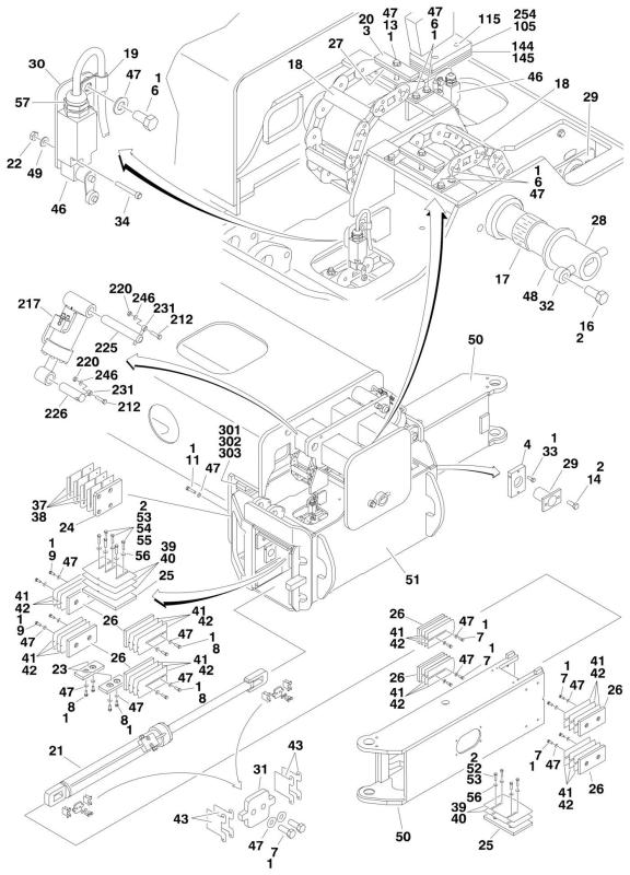
FIGURE 1-1. AXLE INSTALLATIONS
10 |
1250AJP |
3121172 |
|
|
|
|
SECTION 1 - FRAME |
||
|
|
|
FIGURE 1-1. AXLE INSTALLATIONS |
|
|
|
|
|
|
|
|
|
|
|
ITEM |
PART NUMBER |
QTY |
DESCRIPTION |
REV |
|
|
|
|
|
|
|
|
|
|
|
Ref |
AXLE INSTALLATIONS - COMMON PARTS |
|
|
|
|
0271934 |
Ref |
Fixed Axle |
K |
|
|
|
0271521 |
Ref |
Oscillating Axle |
K |
|
|
1 |
0100011 |
AR |
Compound, Locking |
|
|
|
2 |
0100019 |
AR |
Compound, Locking |
|
|
|
3 |
0100081 |
AR |
Adhesive #454 |
|
|
|
4 |
0363037 |
4 |
Bar, Stop |
|
|
|
6 |
0641606 |
40 |
Bolt 3/8in-16NC x 3/4in |
|
|
|
7 |
0641608 |
48 |
Bolt 3/8in-16NC x 1in |
|
|
|
8 |
0641609 |
32 |
Bolt 3/8in-16NC x 1-1/8in |
|
|
|
9 |
0641611 |
16 |
Bolt 3/8in-16NC x 1-3/8in |
|
|
|
11 |
0641613 |
8 |
Bolt 3/8in-16NC x 1-5/8in |
|
|
|
13 |
|
Ref |
Bolt Options: |
|
|
|
13 |
0641620 |
4 |
Fixed Axle - Bolt 3/8in-16NC x 2-1/2in |
|
|
|
13 |
0641624 |
4 |
Oscillating Axle - Bolt 3/8in-16NC x 3in |
|
|
|
14 |
0641808 |
8 |
Bolt 1/2in-13NC x 1in |
|
|
|
16 |
0642214 |
1 |
Bolt 3/4in-10NC x 1-3/4in |
|
|
|
17 |
0962033 |
2 |
Bushing |
|
|
|
18 |
1180358 |
4 |
Carrier |
|
|
|
18 |
7024365 |
AR |
24 in Section Repair Kit (Includes Inner and Outer Links, |
|
|
|
|
|
|
Joining Bars and Rollers, and Assembling Hardware) |
|
|
|
18 |
7024366 |
1 |
Mounting Bracket Kit (Includes Mounting Brackets for Both |
|
|
|
|
|
|
Ends, 1 Roller Assembly and Assembling Hardware) |
|
|
|
19 |
1320263 |
4 |
Clamp, Cable |
|
|
|
20 |
1320298 |
4 |
Clamp, Hose |
|
|
|
21 |
1684102 |
4 |
Axle Extension Cylinder Assembly (See CYLINDER SECTION |
|
|
|
|
|
|
for Breakdown) |
|
|
|
22 |
3310805 |
8 |
Locknut #8-32NC |
|
|
|
23 |
3340881 |
8 |
Pad, Wear |
|
|
|
24 |
3340907 |
2 |
Pad, Axle (Use p/n 1001161401) |
|
|
|
25 |
3340946 |
8 |
Pad, Wear (Use p/n 1001161402) |
|
|
|
26 |
3340932 |
32 |
Pad, Wear (Use p/n 1001161403) |
|
|
|
27 |
3340939 |
8 |
Pad, Rubber |
|
|
|
28 |
3422918 |
1 |
Pin |
|
|
|
29 |
3422960 |
4 |
Pin |
|
|
|
30 |
3573294 |
4 |
Plate |
|
|
|
31 |
3573335 |
8 |
Plate |
|
|
|
32 |
3841287 |
1 |
Keeper, Pin |
|
|
|
33 |
3900270 |
4 |
Bolt, Shoulder 1/2in -13NC x 1-1/2in |
|
|
|
34 |
3930820 |
8 |
Capscrew #8-32NC x 1-1/4in |
|
|
|
37 |
4071035 |
2 |
Shim #18 Gauge |
|
|
|
38 |
4071036 |
4 |
Shim #11 Gauge |
|
|
|
39 |
4071054 |
8 |
Shim #18 Gauge |
|
|
|
40 |
4071055 |
12 |
Shim #11 Gauge |
|
|
|
41 |
4071039 |
24 |
Shim #18 Gauge |
|
|
|
42 |
4071040 |
36 |
Shim #11 Gauge |
|
|
|
43 |
4071042 |
24 |
Shim #16 Gauge |
|
|
|
46 |
|
Ref |
Switch, Limit Options: |
|
|
|
46 |
4360322 |
4 |
Switch, Limit (Use p/n 4360578) (Prior to SN 0300074420) |
|
|
|
46 |
4360549 |
4 |
Switch, Limit (Use p/n 4360578) (SN 0300074420 through |
|
|
3121172 |
|
|
1250AJP |
11 |
||
SECTION 1 - FRAME
ITEM |
PART NUMBER |
QTY |
DESCRIPTION |
REV |
|
|
|
|
|
|
|
|
0300080868) |
|
46 |
4360578 |
4 |
Switch, Limit (SN 0300080869 to Present) |
|
47 |
4711600 |
140 |
Flatwasher 3/8in Thin |
|
48 |
4740461 |
1 |
Thrustwasher |
|
49 |
4750800 |
8 |
Flatwasher #8 Regular |
|
50 |
4846637 |
4 |
Extension, Axle |
|
51 |
4846383 |
1 |
Box, Axle Pivot |
|
52 |
0681813 |
12 |
Bolt 1/2in-13NC x 1-5/8in (Grade 8) |
|
53 |
0681814 |
18 |
Bolt 1/2in-13NC x 1-3/4in (Grade 8) |
|
54 |
0681815 |
12 |
Bolt 1/2in-13NC x 1-7/8in (Grade 8) |
|
55 |
0681816 |
6 |
Bolt 1/2in-13NC x 2in (Grade 8) |
|
56 |
4711800 |
48 |
Flatwasher 1/2in Thin |
|
57 |
4460968 |
4 |
Connector, Strain Relief |
|
|
|
Ref |
AXLE INSTALLATION - OPTIONAL PARTS |
|
|
0271934 |
Ref |
Fixed Axle |
K |
105 |
0363076 |
2 |
Bar, Stop |
|
115 |
0641814 |
4 |
Bolt 1/2in-13NC x 1-3/4in |
|
144 |
4071049 |
6 |
Shim 11 Gauge |
|
145 |
4071050 |
4 |
Shim 16 Gauge |
|
|
0271521 |
Ref |
Oscillating Axle |
K |
201 to 211 |
|
Ref |
(Illustration and Parts List Usage) |
|
212 |
0642020 |
4 |
Bolt 5/8in-11NC x 2-1/2in |
|
217 |
1684081 |
2 |
Oscillating Axle Cylinder Assembly (See CYLINDER SECTION |
|
|
|
|
for Breakdown) |
|
220 |
3312005 |
4 |
Locknut 5/8in-11NC |
|
225 |
3422833 |
2 |
Pin |
|
226 |
3422915 |
2 |
Pin |
|
231 |
3841258 |
4 |
Keeper, Pin |
|
246 |
4712000 |
4 |
Flatwasher 5/8in Thin |
|
254 |
3520054 |
4 |
Plug |
|
|
0274106 |
Ref |
AXLE STOP BLOCKS INSTALLATION |
A |
301 |
0100019 |
AR |
Compound, Locking |
|
302 |
3931816 |
4 |
Capscrew, Socket Head 1/2in-13NC x 1in |
|
303 |
4220235 |
2 |
Block, Stop |
|
12 |
1250AJP |
3121172 |
SECTION 1 - FRAME
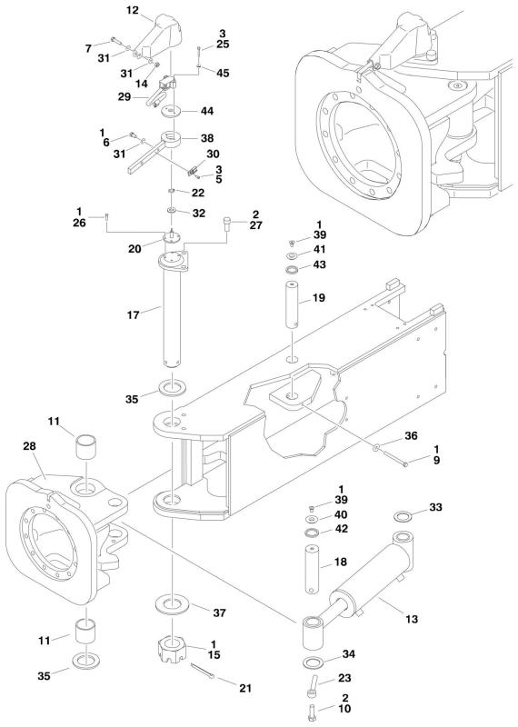
FIGURE 1-2. STEER INSTALLATION
14 |
1250AJP |
3121172 |
|
|
|
SECTION 1 - FRAME |
||
|
|
FIGURE 1-2. STEER INSTALLATION |
|
|
|
|
|
|
|
|
|
ITEM |
PART NUMBER |
QTY |
DESCRIPTION |
REV |
|
|
|
|
|
|
|
|
0271520 |
Ref |
STEER INSTALLATION |
H |
|
1 |
0100011 |
AR |
Compound, Locking |
|
|
2 |
0100019 |
AR |
Compound, Locking |
|
|
3 |
0100035 |
AR |
Compound, Locking |
|
|
5 |
0630464 |
4 |
Screw, Button Head #10-24NC x 1/2in |
|
|
6 |
0641505 |
4 |
Bolt 5/16inin-18NC x 5/8in |
|
|
7 |
0641511 |
4 |
Bolt 5/16in-18NC x 1-3/8in |
|
|
9 |
0641634 |
4 |
Bolt 3/8in-16NC x 4-1/4in |
|
|
10 |
0642016 |
4 |
Bolt 5/8in-11NC x 2in |
|
|
11 |
0962423 |
8 |
Bushing |
|
|
12 |
1671040 |
4 |
Cover, Sensor |
|
|
13 |
1684314 |
4 |
Steer Cylinder Assembly |
|
|
14 |
3311505 |
4 |
Locknut 5/16in-18NC |
|
|
15 |
3300464 |
4 |
Nut, Slotted |
|
|
17 |
3422917 |
4 |
Kingpin |
|
|
18 |
3422940 |
4 |
Pin, Steer Cylinder (Outer) |
|
|
19 |
3422941 |
4 |
Pin, Steer Cylinder (Inner) |
|
|
20 |
|
Ref |
Pin, Sensor Options: |
|
|
20 |
3422942 |
4 |
Pin, Sensor (Use p/n 3423256) (Prior to SN 0300090594) |
|
|
20 |
3423256 |
4 |
Pin, Sensor (SN 0300090594 to Present) |
|
|
21 |
3451214 |
4 |
Pin, Cotter 3/8in x 3-1/2in |
|
|
22 |
3760383 |
4 |
Ring, Retaining |
|
|
23 |
3841258 |
4 |
Keeper, Pin |
|
|
25 |
3931020 |
8 |
Capscrew #10-24NC x 1-1/4in |
|
|
26 |
3931412 |
16 |
Capscrew 1/4in-20NC x 3/4in |
|
|
27 |
3932024 |
8 |
Capscrew 5/8in-11NC x 1-1/2in |
|
|
28 |
|
Ref |
Spindle Options: |
|
|
28 |
4130387 |
4 |
Spindle (Use p/n 1001099632) (Prior to SN 0300100131) |
|
|
28 |
4130416 |
4 |
Spindle (Use p/n 1001099632) (SN 0300100131 to Present) |
|
|
29 |
4360505 |
4 |
Switch, Rotary Angle Sensor (Steer) |
|
|
30 |
4460914 |
4 |
Terminal |
|
|
31 |
4711500 |
12 |
Flatwasher 5/16in Thin |
|
|
32 |
4711800 |
4 |
Flatwasher 1/2in Thin |
|
|
33 |
4740181 |
4 |
Thrustwasher |
|
|
34 |
4740229 |
4 |
Thrustwasher |
|
|
35 |
4740505 |
8 |
Thrustwasher |
|
|
36 |
4751600 |
4 |
Flatwasher 3/8in Regular |
|
|
37 |
4755000 |
4 |
Flatwasher 2-1/2in Regular |
|
|
38 |
|
Ref |
Arm, Steer Options: |
|
|
38 |
4846494 |
4 |
Arm, Steer (Use p/n 0200833) (Prior to SN 0300090594) |
|
|
38 |
0200833 |
4 |
Arm, Steer (SN 0300090594 to Present) |
|
|
39 |
0741606 |
8 |
Screw, Countersunk 3/8in-16NC x 3/4in |
|
|
40 |
1120549 |
4 |
Cap, Seal (Outer) |
|
|
41 |
1120550 |
4 |
Cap, Seal (Inner) |
|
|
42 |
3960551 |
4 |
Seal (Outer) |
|
|
43 |
3960552 |
4 |
Seal (Inner) |
|
|
44 |
0080277 |
4 |
Adapter, Angle Sensor Pilot (SN 0300090594 to Present) |
|
|
45 |
4750800 |
8 |
Flatwasher #8 Regular |
|
|
3121172 |
1250AJP |
15 |
SECTION 1 - FRAME
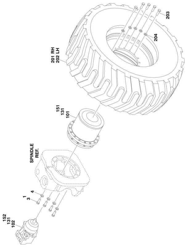
FIGURE 1-3. TIRE AND WHEEL DRIVE INSTALLATION
16 |
1250AJP |
3121172 |
SECTION 1 - FRAME
FIGURE 1-3. TIRE AND WHEEL DRIVE INSTALLATION
|
ITEM |
PART NUMBER |
QTY |
DESCRIPTION |
REV |
|
|
|
|
|
|
|
|
|
|
|
Ref |
WHEEL DRIVE INSTALLATION |
|
|
|
|
0271522 |
Ref |
With Bonfiglioli Drive Hub (Prior to SN 0300103907) |
E |
|
|
|
0275685 |
Ref |
With Bonfiglioli Drive Hub (SN 0300103907 to Present) |
B |
|
|
|
1001104324 |
Ref |
With Reggiana Riduttori Drive Hub |
A |
|
|
1 |
0100019 |
AR |
Compound, Locking |
|
|
|
3 |
0701617 |
48 |
Bolt M16 x 45mm (12 Per Wheel) |
|
|
|
4 |
4892000 |
48 |
Flatwasher 5/8in Hardened (12 Per Wheel) |
|
|
|
|
0272258 |
Ref |
HUB AND MOTOR ASSEMBLY (Prior to SN 0300079667) |
B |
|
|
|
|
Ref |
Note: Original Equipment hub may have been replaced with |
|
|
|
|
|
|
Service Replacement. Refer to tag on hub for identification |
|
|
|
|
|
|
before ordering parts. |
|
|
|
101 |
2780248 |
4 |
Drive Hub Assembly (Use p/n 2780283 - See DRIVE HUB |
|
|
|
|
|
|
ASSEMBLY for Breakdown. See HUB AND MOTOR ASSEMBLY |
|
|
|
|
|
|
for replacement components for Service Replacement p/n |
|
|
|
|
|
|
2780283.) |
|
|
|
102 |
3160291 |
4 |
Drive Motor Assembly (See DRIVE MOTOR ASSEMBLY for |
|
|
|
|
|
|
Breakdown) |
|
|
|
131 |
|
Ref |
HUB AND MOTOR ASSEMBLY (SN 0300079667 through |
|
|
|
|
|
|
0300103906) |
|
|
|
|
|
Ref |
Note: For Machines Built S/N 0300079596 to S/N 0300083552, |
|
|
|
|
|
|
Original Equipment may have been replaced with Service |
|
|
|
|
|
|
Replacement. Refer to tag on hub for identification before |
|
|
|
|
|
|
ordering parts. |
|
|
|
131 |
2780279 |
4 |
Hub and Motor Assembly (Use p/n 2780284 - See HUB AND |
|
|
|
|
|
|
MOTOR ASSEMBLY for Breakdown. See HUB AND MOTOR |
|
|
|
|
|
|
ASSEMBLY for replacement components for Service |
|
|
|
|
|
|
Replacement p/n 2780284.) (SN 0300079667 through |
|
|
|
|
|
|
0300083555) |
|
|
|
131 |
2780284 |
4 |
Hub and Motor Assembly (See HUB AND MOTOR ASSEMBLY |
|
|
|
|
|
|
for Breakdown) (SN 0300083556 through 0300103906) |
|
|
|
|
|
Ref |
HUB AND MOTOR ASSEMBLY (SN 0300103907 to Present) |
|
|
|
|
2780286 |
Ref |
With Bonfiglioli Drive Hub |
|
|
|
|
1001104315 |
Ref |
With Reggiana Riduttori Drive Hub |
|
|
|
151 |
|
Ref |
Drive Hub Assembly Options: |
|
|
|
|
|
Ref |
Note: Various brands used on Machines Built S/N 0300103907 |
|
|
|
|
|
|
to Present. When replacing complete hub, note that all 4 hubs |
|
|
|
|
|
|
must be the same brand. |
|
|
|
|
|
Ref |
Note: Various brands used on Machines Built S/N 0300103907 |
|
|
|
|
|
|
to Present. Identify brand before ordering replacement parts. |
|
|
|
151 |
2780290 |
4 |
Bonfiglioli Hub (Use p/n 1001093243) (See DRIVE HUB |
|
|
|
|
|
|
ASSEMBLY - BONFIGLIOLI for Breakdown) (SN 0300103907 |
|
|
|
|
|
|
to Present) |
|
|
|
151 |
1001104325 |
4 |
Reggiana Riduttori Hub (See DRIVE HUB ASSEMBLY - |
|
|
|
|
|
|
REGGIANA RIDUTTORI for Breakdown) (Prior to SN |
|
|
|
|
|
|
0300079667) |
|
|
|
152 |
3160339 |
4 |
Drive Motor Assembly (See DRIVE MOTOR ASSEMBLY for |
|
|
|
|
|
|
Breakdown) |
|
|
|
|
|
Ref |
TIRE AND WHEEL INSTALLATIONS |
|
|
|
|
0271852 |
Ref |
Foam-Filled Tires |
B |
|
|
|
1001115961 |
Ref |
Solid Tires |
A |
|
|
|
|
Ref |
Note: Assemblies may require ballast/foam filling to |
|
|
|
|
|
|
manufacturer's specifications prior to installing on a machine. |
|
|
|
|
|
|
Refer to Operation and Safety or Service and Maintenance |
|
|
|
|
|
|
Manuals. Purchase individual tire and/or rim only if able to |
|
|
|
|
|
|
foam fill tire and wheel assembly, otherwise, purchase |
|
|
|
|
|
|
complete assembly. |
|
|
3121172 |
|
|
1250AJP |
17 |
||
SECTION 1 - FRAME
ITEM |
PART NUMBER |
QTY |
DESCRIPTION |
REV |
|
|
|
|
|
201 |
|
Ref |
Right Side Tire and Wheel Assembly Options: |
|
201 |
0272055 |
2 |
Foam-Filled Tire and Wheel Assembly |
|
201 |
1001112716 |
2 |
Solid Tire and Wheel Assembly |
|
202 |
|
Ref |
Left Side Tire and Wheel Assembly Options: |
|
202 |
0272056 |
2 |
Foam-Filled Tire and Wheel Assembly |
|
202 |
1001112669 |
2 |
Solid Tire and Wheel Assembly |
|
203 |
0701619 |
64 |
Bolt M16 x 55mm (16 Per Wheel) |
|
204 |
4892000 |
64 |
Flatwasher 5/8in Hardened (16 Per Wheel) |
|
18 |
1250AJP |
3121172 |
SECTION 1 - FRAME
FIGURE 1-4. DRIVE HUB ASSEMBLY (Prior to SN 0300079667)
20 |
1250AJP |
3121172 |
|
|
|
|
SECTION 1 - FRAME |
||
|
|
FIGURE 1-4. DRIVE HUB ASSEMBLY (Prior to SN 0300079667) |
|
|
||
|
|
|
|
|
|
|
|
ITEM |
PART NUMBER |
QTY |
DESCRIPTION |
REV |
|
|
|
|
|
|
|
|
|
|
2780248 |
Ref |
DRIVE HUB ASSEMBLY |
C |
|
|
|
|
Ref |
Note: Unless there is capability to torque shaft (item 4) to 626 |
|
|
|
|
|
|
ft/lbs. (850Nm) Repair beyond this level is NOT advised. |
|
|
|
|
|
Ref |
Note: Original Equipment p/n 2780248 hub may have been |
|
|
|
|
|
|
replaced with Service Replacement p/n 2780283. - See HUB |
|
|
|
|
|
|
AND MOTOR ASSEMBLY for Breakdown. Refer to tag on hub |
|
|
|
|
|
|
for identification before ordering parts. |
|
|
|
1 |
7024028 |
4 |
Gear, Planet |
|
|
|
2 |
7024029 |
3 |
Gear, Planet |
|
|
|
3 |
7022535 |
1 |
Gear, Sun |
|
|
|
4 |
7022536 |
1 |
Nut, Shaft |
|
|
|
5 |
7021388 |
3 |
Pin, Planet |
|
|
|
7 |
7022537 |
1 |
Carrier, Planet |
|
|
|
8 |
7022538 |
1 |
Cover |
|
|
|
9 |
7024967 |
1 |
Button, Thrust |
|
|
|
10 |
7024029 |
3 |
Bearing, Roller |
|
|
|
11 |
7024028 |
4 |
Bearing, Roller |
|
|
|
12 |
7022536 |
1 |
Bearing, Ball |
|
|
|
13 |
7022540 |
2 |
Bolt, Hex |
|
|
|
14 |
7024029 |
3 |
Ring, Retaining |
|
|
|
15 |
7024028 |
4 |
Ring, Retaining |
|
|
|
16 |
7022546 |
1 |
Ring, Retaining |
|
|
|
17 |
7024029 |
3 |
Ring, Stay |
|
|
|
19 |
7024966 |
1 |
O-Ring |
|
|
|
20 |
7024968 |
1 |
Seal, Face |
|
|
|
21 |
7022550 |
2 |
Plug |
|
|
|
22 |
7022540 |
2 |
Seal, Ring |
|
|
|
23 |
7022536 |
2 |
Bolt |
|
|
|
24 |
See Note |
2 |
Ball (Note: Not Available for Purchase) |
|
|
|
27 |
See Note |
2 |
Bolt (Note: Not Available for Purchase) |
|
|
|
28 |
See Note |
2 |
Washer (Note: Not Available for Purchase) |
|
|
|
30 |
7022556 |
1 |
Gear, Ring |
|
|
|
33 |
7022540 |
1 |
O-Ring |
|
|
|
40 |
7024030 |
3 |
Gear, Planet |
|
|
|
41 |
7022559 |
1 |
Carrier, Planet |
|
|
|
42 |
7022560 |
1 |
Gear, Sun |
|
|
|
43 |
7022540 |
1 |
Gear, Sun |
|
|
|
44 |
7022540 |
1 |
Shaft, Input |
|
|
|
45 |
7011326 |
3 |
Pin, Planet |
|
|
|
46 |
7024030 |
3 |
Bearing, Roller |
|
|
|
47 |
7022564 |
1 |
Ring, Retaining |
|
|
|
48 |
7024030 |
3 |
Ring, Retaining |
|
|
|
50 |
7024030 |
3 |
Ring, Stay |
|
|
|
51 |
7022567 |
1 |
Cover |
|
|
|
52 |
7022568 |
1 |
Thrustwasher |
|
|
|
53 |
7022536 |
2 |
Bolt |
|
|
|
54 |
7022540 |
1 |
O-Ring |
|
|
|
55 |
7022540 |
1 |
Spring, Pressure |
|
|
|
60 |
7022572 |
1 |
Spindle |
|
|
|
61 |
7022573 |
1 |
Piston |
|
|
3121172 |
|
|
1250AJP |
21 |
||
SECTION 1 - FRAME
ITEM |
PART NUMBER |
QTY |
DESCRIPTION |
REV |
|
|
|
|
|
62 |
7022574 |
1 |
Coupler |
|
63 |
7022575 |
1 |
Ring, Locator |
|
64 |
7021354 |
1 |
Plate, Back-up |
|
65 |
7022576 |
1 |
Plate, Back-up |
|
66 |
7022577 |
1 |
Ring, Retaining |
|
67 |
7022578 |
1 |
Ring, Retaining |
|
68 |
7022509 |
1 |
Ring, Retaining |
|
69 |
7022579 |
2 |
Bolt |
|
72 |
7022580 |
4 |
Disc, Brake |
|
73 |
7022580 |
5 |
Disc, Brake |
|
74 |
7022580 |
16 |
Spring |
|
75 |
7022581 |
2 |
Ring, Back-up |
|
76 |
7022581 |
1 |
Seal |
|
77 |
7022581 |
2 |
Ring, Back-up |
|
78 |
7022581 |
1 |
Seal |
|
87 |
7024032 |
1 |
O-Ring |
|
120 |
See Note |
1 |
Motor Assembly (Note: See Separate Parts List) |
|
121 |
7024031 |
1 |
O-Ring (Not Shown) |
|
224 |
7024969 |
2 |
Pin, Slotted (Not Shown) |
|
251 |
7022581 |
1 |
Kit 1 - Brake Seal Kit (Includes Items 75-78) |
|
252 |
7022580 |
1 |
Kit 2 - Brake Disc Kit (Includes Items 72-74) |
|
252 |
7022536 |
1 |
Kit 3 - Bearing Kit (Includes Items 4, 12, 23 & 53) |
|
252 |
7024030 |
1 |
Kit 4 - Planet Gear and Bearing Kit (Includes Items 40, 46, 48 & |
|
|
|
|
50) |
|
252 |
7024029 |
1 |
Kit 5 - Planet Gear and Bearing Kit (Includes Items 2, 10, 14 & |
|
|
|
|
17) |
|
252 |
7024028 |
1 |
Kit 6 - Planet Gear and Bearing Kit (Includes Items 1, 11 & 15) |
|
252 |
7022540 |
1 |
Kit 7 - Mechanical Disconnect Kit (Includes Items 13, 22, 33, 43, |
|
|
|
|
44, 54 & 55) |
|
22 |
1250AJP |
3121172 |
SECTION 1 - FRAME
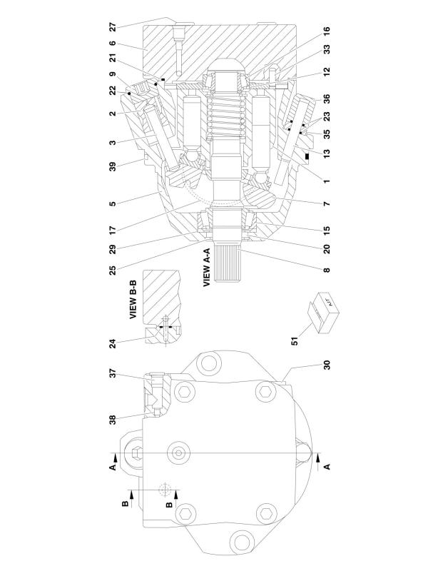
FIGURE 1-5. DRIVE MOTOR ASSEMBLY (Prior to SN 0300079667)
24 |
1250AJP |
3121172 |
|
|
|
SECTION 1 - FRAME |
||
|
FIGURE 1-5. DRIVE MOTOR ASSEMBLY (Prior to SN 0300079667) |
|
|
||
|
|
|
|
|
|
ITEM |
PART NUMBER |
QTY |
DESCRIPTION |
REV |
|
|
|
|
|
|
|
|
3160291 |
Ref |
DRIVE MOTOR ASSEMBLY |
C |
|
1 |
7012716 |
1 |
Rotary Group Assembly |
|
|
2 |
See Note |
1 |
Piston, Control (Note: Not Available - Purchase Complete |
|
|
3 |
See Note |
1 |
Rod, Piston (Note: Not Available - Purchase Complete Motor) |
|
|
5 |
See Note |
1 |
Housing (Note: Not Available - Purchase Complete Motor) |
|
|
6 |
See Note |
1 |
Plate, Port (Note: Not Available - Purchase Complete Motor) |
|
|
7 |
7024036 |
1 |
Plate, Swash |
|
|
8 |
7024037 |
1 |
Driveshaft |
|
|
9 |
See Note |
1 |
Plug, Screw (Note: Not Available for Purchase) |
|
|
12 |
7012704 |
1 |
Shim |
|
|
13 |
See Note |
1 |
Stop Screw (Note: Not Available for Purchase) |
|
|
15 |
7024038 |
1 |
Bearing |
|
|
16 |
7012706 |
1 |
Bearing |
|
|
17 |
7024039 |
2 |
Shell, Cradle |
|
|
20 |
7024034 |
1 |
Seal, Shaft |
|
|
21 |
7024034 |
1 |
O-Ring |
|
|
22 |
7024034 |
1 |
O-Ring |
|
|
23 |
7024034 |
2 |
O-Ring |
|
|
24 |
7024034 |
1 |
Seal |
|
|
25 |
7012715 |
1 |
V-Ring |
|
|
27 |
7024040 |
4 |
Screw, Sockethead M12 x 60mm |
|
|
29 |
See Note |
1 |
Ring, Stop (Note: Not Available for Purchase) |
|
|
30 |
See Note |
1 |
Plug (Note: Not Available for Purchase) |
|
|
33 |
See Note |
1 |
Pin, Dowel (Note: Not Available for Purchase) |
|
|
35 |
See Note |
1 |
Nut M10 (Note: Not Available for Purchase) |
|
|
36 |
See Note |
1 |
Nut, Cap M10 (Note: Not Available for Purchase) |
|
|
37 |
7024034 |
1 |
Plug |
|
|
38 |
7024041 |
1 |
Orifice |
|
|
39 |
7024034 |
1 |
O-Ring |
|
|
51 |
7024034 |
1 |
Seal Kit (Includes Items 20-24, 37 & 39) |
|
|
3121172 |
1250AJP |
25 |
SECTION 1 - FRAME
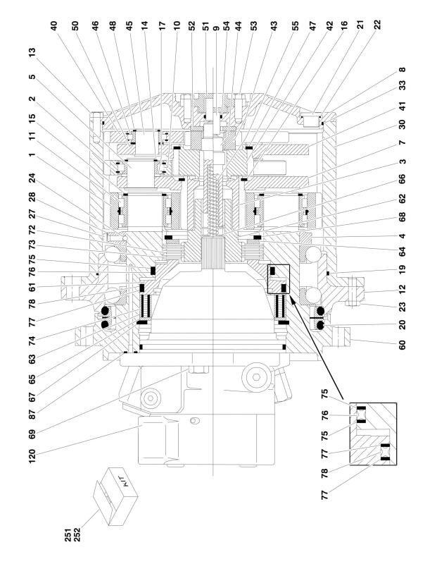
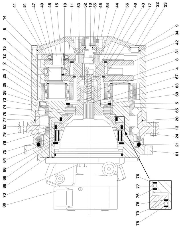
FIGURE 1-6. HUB AND MOTOR ASSEMBLY (SN 0300079667 through 0300083555)
26 |
1250AJP |
3121172 |
SECTION 1 - FRAME
3121172 |
1250AJP |
27 |
SECTION 1 - FRAME
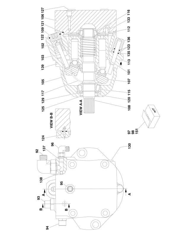
FIGURE 1-6. HUB AND MOTOR ASSEMBLY (SN 0300079667 through 0300083555)
|
ITEM |
PART NUMBER |
QTY |
DESCRIPTION |
REV |
|
|
|
|
|
|
|
|
|
|
2780279 |
Ref |
DRIVE HUB AND MOTOR ASSEMBLY |
B |
|
|
|
|
Ref |
Note: For Machines Buil S/N 0300079667 to S/N 0300083556, |
|
|
|
|
|
|
Original Equipment p/n 2780279 may have been replaced with |
|
|
|
|
|
|
Service Replacement p/n 2780284 - See HUB AND MOTOR |
|
|
|
|
|
|
ASSEMBLY for Breakdown. Refer to tag on hub for |
|
|
|
|
|
|
identification before ordering parts. |
|
|
|
|
|
Ref |
Note: Unless there is capability to torque shaft (item 5) to 626 |
|
|
|
|
|
|
ft/lbs. (850Nm) Repair beyond this level is NOT advised. |
|
|
|
1 |
2780248 |
1 |
Hub, Torque |
|
|
|
2 |
7024028 |
4 |
Gear, Planet |
|
|
|
3 |
7024029 |
3 |
Gear, Planet |
|
|
|
4 |
7022535 |
1 |
Gear, Sun |
|
|
|
5 |
7022536 |
1 |
Nut, Shaft |
|
|
|
6 |
7021388 |
3 |
Pin, Planet |
|
|
|
8 |
7022537 |
1 |
Carrier, Planet |
|
|
|
9 |
7022538 |
1 |
Cover |
|
|
|
10 |
7024967 |
1 |
Button, Thrust |
|
|
|
11 |
7024029 |
3 |
Bearing, Roller |
|
|
|
12 |
7024028 |
4 |
Bearing, Roller |
|
|
|
13 |
7022536 |
1 |
Bearing, Ball |
|
|
|
14 |
7022540 |
2 |
Bolt, Hex |
|
|
|
15 |
7024029 |
3 |
Ring, Retaining |
|
|
|
16 |
7024028 |
4 |
Ring, Retaining |
|
|
|
17 |
7022546 |
1 |
Ring, Retaining |
|
|
|
18 |
7024029 |
3 |
Ring, Stay |
|
|
|
20 |
7024966 |
1 |
O-Ring |
|
|
|
21 |
7024968 |
1 |
Seal, Face |
|
|
|
22 |
7022550 |
2 |
Plug |
|
|
|
23 |
7022540 |
2 |
Seal, Ring |
|
|
|
24 |
7022536 |
2 |
Bolt |
|
|
|
25 |
See Note |
2 |
Ball (Note: Not available for purchase) |
|
|
|
28 |
See Note |
2 |
Bolt (Note: Not Available for Purchase) |
|
|
|
29 |
See Note |
2 |
Washer (Note: Not Available for Purchase) |
|
|
|
31 |
7022556 |
1 |
Gear, Ring |
|
|
|
34 |
7022540 |
1 |
O-Ring |
|
|
|
41 |
7024030 |
3 |
Gear, Planet |
|
|
|
42 |
7022559 |
1 |
Carrier, Planet |
|
|
|
43 |
7022560 |
1 |
Gear, Sun |
|
|
|
44 |
7022540 |
1 |
Gear, Sun |
|
|
|
45 |
7022540 |
1 |
Shaft, Input |
|
|
|
46 |
7011326 |
3 |
Pin, Planet |
|
|
|
47 |
7024030 |
3 |
Bearing, Roller |
|
|
|
48 |
7022564 |
1 |
Ring, Retaining |
|
|
|
49 |
7024030 |
3 |
Ring, Retaining |
|
|
|
51 |
7024030 |
3 |
Ring, Stay |
|
|
|
52 |
7022567 |
1 |
Cover |
|
|
|
53 |
7022568 |
1 |
Thrustwasher |
|
|
|
54 |
7022536 |
2 |
Bolt |
|
|
|
55 |
7022540 |
1 |
O-Ring |
|
|
|
56 |
7022540 |
1 |
Spring, Pressure |
|
|
|
61 |
7022572 |
1 |
Spindle |
|
|
28 |
|
|
|
1250AJP |
3121172 |
|
|
|
|
|
SECTION 1 - FRAME |
||
|
|
|
|
|
|
|
|
ITEM |
PART NUMBER |
QTY |
DESCRIPTION |
REV |
|
|
|
|
|
|
|
|
|
62 |
7022573 |
1 |
Piston |
|
|
|
63 |
7022574 |
1 |
Coupler |
|
|
|
64 |
7022575 |
1 |
Ring, Locator |
|
|
|
65 |
7021354 |
1 |
Plate, Back-up |
|
|
|
66 |
7022576 |
1 |
Plate, Back-up |
|
|
|
67 |
7022577 |
1 |
Ring, Retaining |
|
|
|
68 |
7022578 |
1 |
Ring, Retaining |
|
|
|
69 |
7022509 |
1 |
Ring, Retaining |
|
|
|
70 |
7022579 |
2 |
Bolt |
|
|
|
73 |
7022580 |
4 |
Disc, Brake |
|
|
|
74 |
7022580 |
5 |
Disc, Brake |
|
|
|
75 |
7022580 |
16 |
Spring |
|
|
|
76 |
7022581 |
2 |
Ring, Back-up |
|
|
|
77 |
7022581 |
1 |
Seal |
|
|
|
78 |
7022581 |
2 |
Ring, Back-up |
|
|
|
79 |
7022581 |
1 |
Seal |
|
|
|
88 |
7024032 |
1 |
O-Ring |
|
|
|
89 |
3160291 |
1 |
Motor Assembly (Note: See Items 101 to 139 for Breakdown) |
|
|
|
90 |
7024031 |
1 |
O-Ring (Not Shown) |
|
|
|
91 |
7024969 |
2 |
Pin, Slotted (Not Shown) |
|
|
|
92 |
2130812 |
1 |
Fitting 90 Degree |
|
|
|
93 |
2110812 |
1 |
Fitting, Straight |
|
|
|
94 |
2110808 |
1 |
Fitting, Straight |
|
|
|
95 |
2110404 |
1 |
Fitting, Straight |
|
|
|
96 |
2130404 |
1 |
Fitting 90 Degree |
|
|
|
97 |
7022581 |
1 |
Kit 1 - Brake Seal Kit (Includes Items 76-79) |
|
|
|
98 |
7022580 |
1 |
Kit 2 - Brake Disc Kit (Includes Items 73-75) |
|
|
|
98 |
7022536 |
1 |
Kit 3 - Bearing Kit (Includes Items 5, 13, 24 & 54) |
|
|
|
98 |
7024030 |
1 |
Kit 4 - Planet Gear and Bearing Kit (Includes Items 41, 47, 49 & |
|
|
|
|
|
|
51) |
|
|
|
98 |
7024029 |
1 |
Kit 5 - Planet Gear and Bearing Kit (Includes Items 3, 11, 15 & |
|
|
|
|
|
|
18) |
|
|
|
98 |
7024028 |
1 |
Kit 6 - Planet Gear and Bearing Kit (Includes Items 2, 12 & 16) |
|
|
|
98 |
7022540 |
1 |
Kit 7 - Mechanical Disconnect Kit (Includes Items 14, 23, 34, 44, |
|
|
|
|
|
|
45, 55 & 56) |
|
|
|
|
3160291 |
Ref |
DRIVE MOTOR ASSEMBLY |
A |
|
|
101 |
7012716 |
1 |
Rotary Group Assembly |
|
|
|
102 |
See Note |
1 |
Piston, Control (Note: Not Available - Purchase Complete) |
|
|
|
103 |
See Note |
1 |
Rod, Piston (Note: Not Available - Purchase Complete) |
|
|
|
105 |
See Note |
1 |
Housing (Note: Not Available - Purchase Complete Motor) |
|
|
|
106 |
See Note |
1 |
Plate, Port (Note: Not Available - Purchase Complete Motor) |
|
|
|
107 |
7024036 |
1 |
Plate, Swash |
|
|
|
108 |
7024037 |
1 |
Driveshaft |
|
|
|
109 |
See Note |
1 |
Plug, Screw (Note: Not Available For Purchase) |
|
|
|
112 |
7012704 |
1 |
Shim |
|
|
|
113 |
See Note |
1 |
Stop Screw (Note: Not Available For Purchase) |
|
|
|
115 |
7024038 |
1 |
Bearing |
|
|
|
116 |
7012706 |
1 |
Bearing |
|
|
|
117 |
7024039 |
2 |
Shell, Cradle |
|
|
|
120 |
7024034 |
1 |
Seal, Shaft |
|
|
|
121 |
7024034 |
1 |
O-Ring |
|
|
|
122 |
7024034 |
1 |
O-Ring |
|
|
3121172 |
|
|
1250AJP |
29 |
||
SECTION 1 - FRAME
ITEM |
PART NUMBER |
QTY |
DESCRIPTION |
REV |
|
|
|
|
|
123 |
7024034 |
2 |
O-Ring |
|
124 |
7024034 |
1 |
Seal |
|
125 |
7012715 |
1 |
V-Ring |
|
127 |
7024040 |
4 |
Screw, Socket Head M12 x 60mm |
|
129 |
See Note |
1 |
Ring, Stop (Note: Not Available For Purchase) |
|
130 |
See Note |
1 |
Plug (Note: Not Available For Purchase) |
|
133 |
See Note |
1 |
Pin, Dowel (Note: Not Available For Purchase) |
|
135 |
See Note |
1 |
Nut M10 (Note: Not Available For Purchase) |
|
136 |
See Note |
1 |
Nut, Cap M10 (Note: Not Available For Purchase) |
|
137 |
7024034 |
1 |
Plug |
|
138 |
7024041 |
1 |
Orifice |
|
139 |
7024034 |
1 |
O-Ring |
|
151 |
7024034 |
1 |
Seal Kit (Includes Items 120-124, 137 & 139) |
|
30 |
1250AJP |
3121172 |
Loading...