


HP PS1810-8G Switch Quick Setup Guide,
and Safety/Regulatory Information
For more detailed instructions and information to set up your switch, view or download the Installation and Getting Started Guide for your switch at www.hp.com/networking/support.
1. Unpack and check included parts. |
■ Documentation kit |
■Switch
■Accessory kit (installation hardware)
■Wall mount AC/DC adapter, or in-line AC/DC adapter and power cord
2.Prepare for installation. To avoid personal injury or product damage, follow the “Safety and Regulatory Information for HP PS1810-8G Switch” on page 6.
3.Mount the switch. Stack the switch with HP ProLiant MicroServers, or mount it on a wall, or on top of or under a horizontal surface. Before stacking it with HP servers or positioning the switch on a horizontal surface, attach the rubber feet that are supplied in the accessory kit.
If you are mounting the switch on a wall or under a surface, do not attach the rubber feet.
Stack with the HP ProLiant MicroServer Gen8: Stack the switch under , or on top of the server.
Caution: The switch has a limitation on how much weight can be placed on top of it. To reduce the risk of personal injury or damage to the equipment, stack no more than two servers on top of the switch.


1
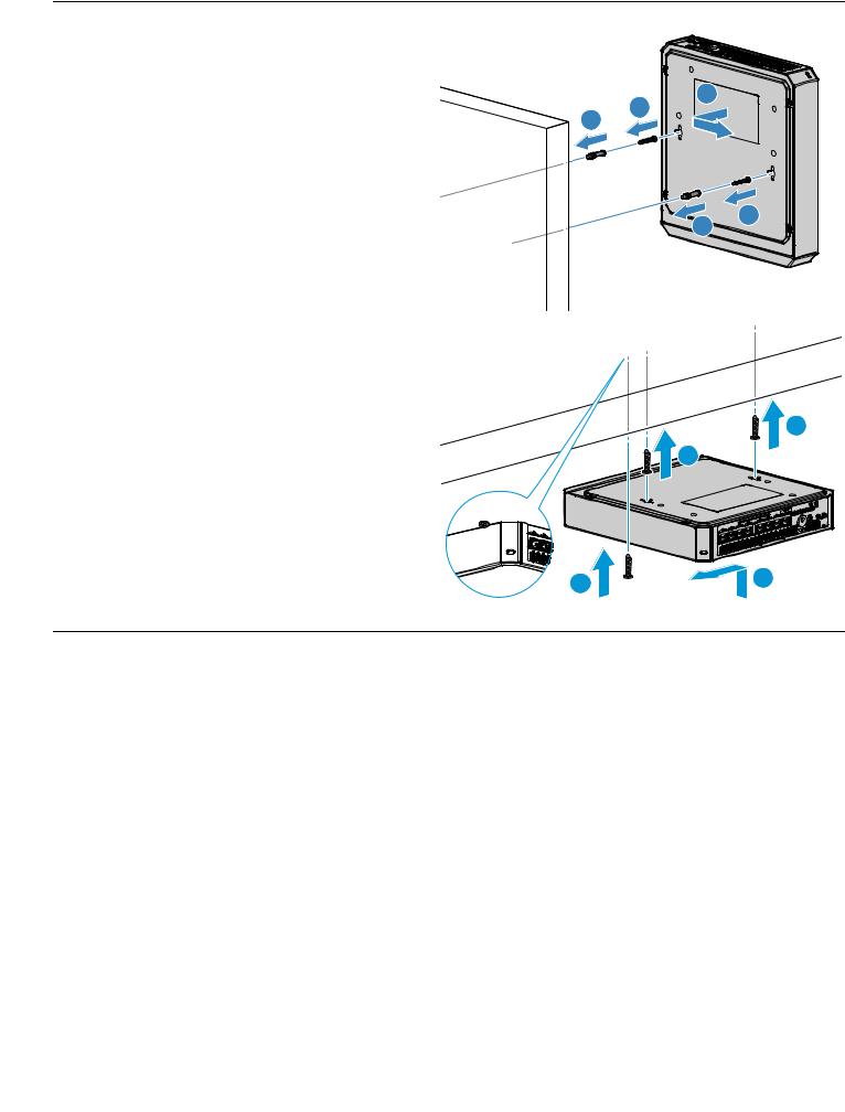
Wall Mounting: Install two 5/8-inch (15.875 mm) Number |
|
12 wood screws, (included) into the mounting surface, |
|
positioned 6.3 inches (160 mm) apart. Use the wall anchors |
|
if necessary. Then, position the switch over the screws and |
|
slide to lock in place. |
3 |
|
|
Important: For wall-mounting, the network ports must be |
2 |
1 |
|
facing up or down. (See “Installation Precautions” on |
|
page 6.) |
|
2
1
Under-Surface Mounting: Install the two screws on the |
|
surface bottom similarly to the procedures for wall |
|
mounting. Then, position the switch over the screws and |
|
slide to lock in place. Install the third screw at the side of |
|
the switch to prevent it from sliding out of the locked |
|
position, if necessary. |
1 |
|
1 |
2
2
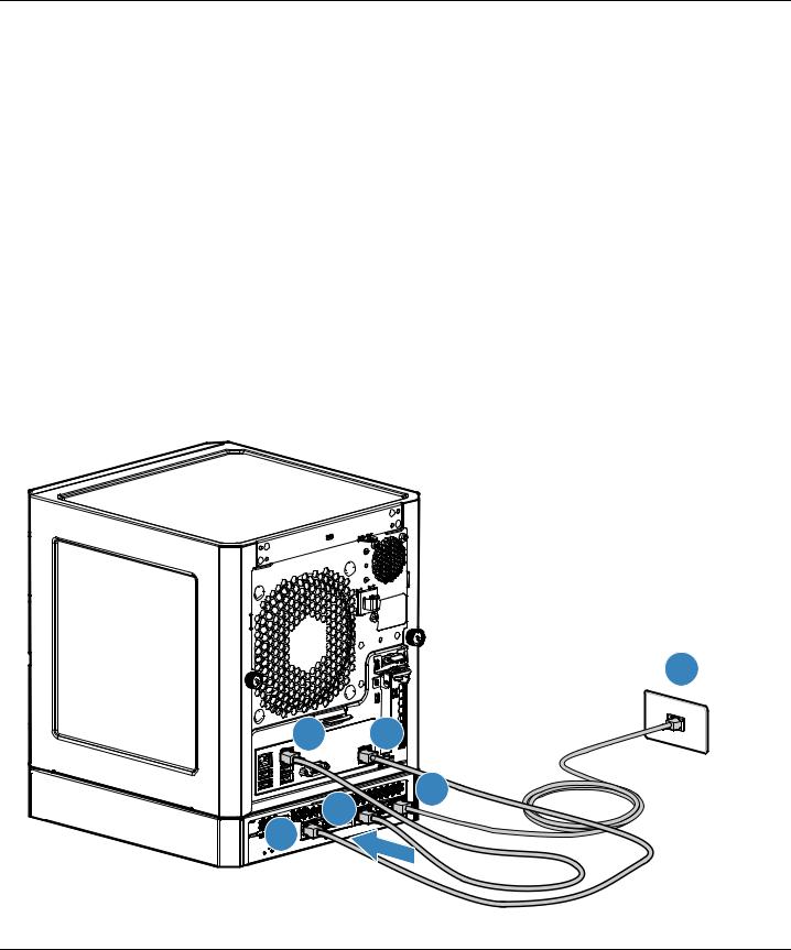
4. Connect the network cables.
Connect network devices, such as an HP ProLiant MicroServer Gen8, to any of the switch’s RJ-45 ports using Class 5E or better Ethernet cables.
Note: Any of the switch’s network ports can be used for the following connections. You do not have to use the specific ports shown in the illustrations.
As shown in the following illustration, for connection to a HP ProLiant MicroServer Gen8, it is recommended that you make the following connections:
■ to – to provide internet access for the switch and server, connect any of the switch ports(1 - 8) to your ISP connection, or to a router that is connected to the internet.
■ to – for data communication between the switch and the server, connect a network cable between any of the available switch ports and either one of the server’s Ethernet ports. Connection to Ethernet port 2 is shown.
■ to – to be able to discover and monitor the health status of HP servers from the switch, connect a network cable between any of the available switch ports and the server’s iLO port.
Note: It is also possible to use a single cable between the switch and server for data and iLO communications, but this requires that you connect to server Ethernet port 1, and requires changes to the server configuration to cause the server Ethernet 1 port to be “shared” for data and iLO communications. See the server documentation on shared iLO mode for more information.
■ You can also connect other devices to the switch, such as printers and PCs, to form your local network.
2
4 |
6 |
|
1 |
5 |
3 |
|
3
 Loading...