


 Loading...
HP R1500 G3 UPS
User Guide
Abstract
This document includes installation, configuration, and operation information for the HP R1500 G3 UPS. This document is for the person who installs and maintains power products. HP assumes you are qualified in the servicing of high-voltage equipment and trained in recognizing hazards in products with hazardous energy levels.
Part Number: 651175-002
August 2012
Edition: 2
© Copyright 2011, 2012 Hewlett-Packard Development Company, L.P.
The information contained herein is subject to change without notice. The only warranties for HP products and services are set forth in the express warranty statements accompanying such products and services. Nothing herein should be construed as constituting an additional warranty. HP shall not be liable for technical or editorial errors or omissions contained herein.
Microsoft®, Windows®, Windows Server®, and Windows Vista® are U.S. registered trademarks of Microsoft Corporation. Bluetooth® is a trademark owned by its proprietor and used by Hewlett-Packard Company under license.

Contents |
|
Component identification............................................................................................................... |
6 |
UPS R1500 G3 overview ........................................................................................................................... |
6 |
UPS front panel......................................................................................................................................... |
6 |
UPS front panel controls ............................................................................................................................. |
7 |
UPS front panel LED indicators .................................................................................................................... |
7 |
UPS R1500 G3 NA/JPN/TWN rear panel .................................................................................................. |
8 |
UPS R1500 G3 INTL rear panel.................................................................................................................. |
9 |
Installation ................................................................................................................................. |
10 |
Precautions............................................................................................................................................. |
10 |
Preparing to install the hardware............................................................................................................... |
10 |
Tools required............................................................................................................................... |
10 |
Selecting a site.............................................................................................................................. |
10 |
Readying the equipment ................................................................................................................. |
11 |
Installing the UPS .................................................................................................................................... |
11 |
Connecting the batteries................................................................................................................. |
12 |
Attaching the UPS front bezel.......................................................................................................... |
13 |
Selecting the UPS voltage configuration............................................................................................ |
14 |
Connecting the host computer ......................................................................................................... |
14 |
Connecting the Network Transient Protectors..................................................................................... |
15 |
Connecting the UPS to utility power ................................................................................................. |
16 |
Connecting devices to the UPS ........................................................................................................ |
16 |
Charging the UPS batteries ............................................................................................................. |
17 |
Powering up the UPS ..................................................................................................................... |
17 |
Installing the optional UPS Network Module ............................................................................................... |
17 |
Connecting the UPS Network Module .............................................................................................. |
19 |
UPS operations........................................................................................................................... |
20 |
Modes of operation ................................................................................................................................. |
20 |
Operate mode .............................................................................................................................. |
20 |
Battery mode ................................................................................................................................ |
20 |
Initiating a self-test ................................................................................................................................... |
20 |
Silencing an audible alarm....................................................................................................................... |
20 |
Powering down the UPS........................................................................................................................... |
21 |
Maintenance .............................................................................................................................. |
22 |
Removing the UPS front bezel ................................................................................................................... |
22 |
Replacing the batteries............................................................................................................................. |
22 |
Important battery safety information ................................................................................................. |
22 |
Battery care and storage guidelines ................................................................................................. |
23 |
UPS battery replacement procedure ................................................................................................. |
23 |
Testing the new battery module ....................................................................................................... |
25 |
Replacing the UPS ................................................................................................................................... |
25 |
Replacing the UPS option card.................................................................................................................. |
25 |
Updating the UPS firmware ...................................................................................................................... |
26 |
Configuring a USB to serial converter............................................................................................... |
26 |
Reassigning the USB COM ports ..................................................................................................... |
27 |
Contents |
3 |
Power management .................................................................................................................... |
29 |
Power Protector software .......................................................................................................................... |
29 |
Troubleshooting .......................................................................................................................... |
31 |
LED and audible alarm troubleshooting ...................................................................................................... |
31 |
UPS does not start ................................................................................................................................... |
32 |
UPS operates on battery only.................................................................................................................... |
32 |
UPS frequently switches between utility and battery power............................................................................ |
32 |
UPS does not provide the expected backup time ......................................................................................... |
32 |
UPS cannot communicate with the host computer......................................................................................... |
33 |
UPS emits a slight clicking noise ................................................................................................................ |
33 |
Site wiring condition................................................................................................................................ |
33 |
Specifications............................................................................................................................. |
34 |
UPS physical specifications....................................................................................................................... |
34 |
UPS input specifications ........................................................................................................................... |
34 |
UPS output specifications.......................................................................................................................... |
34 |
Power protection specifications ....................................................................................................... |
34 |
Voltage specifications .................................................................................................................... |
35 |
Output tolerance specifications........................................................................................................ |
35 |
Output feature specifications ........................................................................................................... |
35 |
Battery specifications ............................................................................................................................... |
35 |
Battery runtime........................................................................................................................................ |
36 |
Environmental specifications ..................................................................................................................... |
36 |
Serial communications port pin assignment................................................................................................. |
36 |
Spares....................................................................................................................................... |
38 |
Ordering spares...................................................................................................................................... |
38 |
UPS spare parts list.................................................................................................................................. |
38 |
Hardware options ................................................................................................................................... |
38 |
Support and other resources ........................................................................................................ |
39 |
Before you contact HP.............................................................................................................................. |
39 |
HP contact information............................................................................................................................. |
39 |
Warranty information.................................................................................................................. |
40 |
Limited warranty ..................................................................................................................................... |
40 |
$250,000 Computer Load Protection Guarantee......................................................................................... |
40 |
Pre-Failure Battery Warranty ..................................................................................................................... |
40 |
Recommended duration of use .................................................................................................................. |
41 |
Regulatory compliance notices ..................................................................................................... |
42 |
Regulatory compliance identification numbers ............................................................................................. |
42 |
Federal Communications Commission notice............................................................................................... |
42 |
FCC rating label............................................................................................................................ |
42 |
FCC Notice, Class A Equipment ...................................................................................................... |
42 |
FCC Notice, Class B Equipment ...................................................................................................... |
42 |
Declaration of conformity for products marked with the FCC logo, United States only....................................... |
43 |
Modifications.......................................................................................................................................... |
43 |
Cables................................................................................................................................................... |
43 |
Canadian notice (Avis Canadien).............................................................................................................. |
43 |
European Union regulatory notice ............................................................................................................. |
44 |
Disposal of waste equipment by users in private households in the European Union ......................................... |
44 |
Japanese notice ...................................................................................................................................... |
45 |
BSMI notice ............................................................................................................................................ |
45 |
Contents |
4 |
Korean notice ......................................................................................................................................... |
45 |
Battery replacement notice........................................................................................................................ |
46 |
Power cord statement for Japan................................................................................................................. |
46 |
Electrostatic discharge................................................................................................................. |
47 |
Preventing electrostatic discharge .............................................................................................................. |
47 |
Grounding methods to prevent electrostatic discharge.................................................................................. |
47 |
Acronyms and abbreviations........................................................................................................ |
48 |
Documentation feedback ............................................................................................................. |
49 |
Index......................................................................................................................................... |
50 |
Contents 5
Component identification
UPS R1500 G3 overview
The HP UPS R1500 G3 features a 1U rack-mount design and offers power protection for loads up to 1440 VA/1000 W (NA), 1200 VA/900 W (JPN/TWN) or 1500 VA/1000 W (INTL).
To benefit from the latest product enhancements, update to the latest versions of UPS firmware and software.
NOTE: To download the latest versions of UPS firmware and software, see the HP website (http://www.hp.com/go/rackandpower).
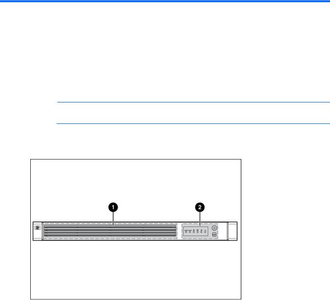
UPS front panel
Item |
Description |
|
|
1 |
Battery compartment |
2 |
Control buttons and LED display |
Component identification 6
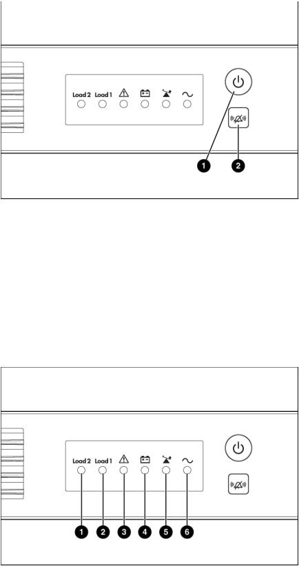
UPS front panel controls
Item |
Description |
Function |
|
|
|
1 |
Power On/Standby button |
Powers up the UPS ("Powering up the UPS" on page 17). |
|
|
|
|
|
Powers down the UPS ("Powering down the UPS" on page |
|
|
21). |
|
|
|
2 |
Test/Alarm Reset button |
Initiates a self-test ("Initiating a self-test" on page 20). |
|
|
|
|
|
Silences UPS alarms ("Silencing an audible alarm" on page |
|
|
20). |
|
|
|
UPS front panel LED indicators
Component identification 7
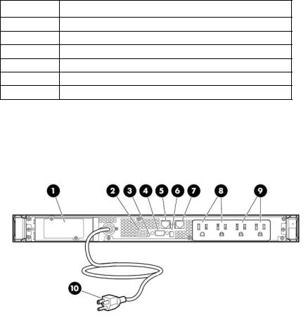
Item |
LED description |
1Load Segment 2
2Load Segment 1
3General Alarm
4On Battery
5Overload
6Power On
For more information, see "LED and audible alarm troubleshooting (on page 31)."
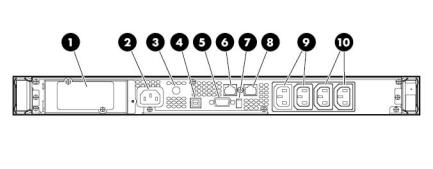
UPS R1500 G3 NA/JPN/TWN rear panel
Item |
Description |
|
|
1 |
UPS option card slot |
2 |
USB communications port |
3 |
Site Wiring Fault LED |
4 |
Serial communications port |
|
|
5 |
Network Transient Protector IN jack |
6 |
Voltage configuration DIP switches |
7 |
Network Transient Protector OUT jack |
8 |
Load segment 1 (two NEMA 5-15 output receptacles for surge |
|
and battery backup protection) |
9 |
Load segment 2 (two NEMA 5-15 output receptacles for surge |
|
and battery backup protection) |
10 |
Input power cord with NEMA 5-15 plug (BSMI approved for |
|
TWN) |
|
|
Component identification 8
UPS R1500 G3 INTL rear panel
Item |
Description |
|
|
1 |
UPS option card slot |
2 |
Input power connector (IEC-320-C14 power inlet) |
3 |
Input circuit breaker |
4 |
USB communications port |
5 |
Serial communications port |
6 |
Network Transient Protector IN jack |
7 |
Voltage configuration DIP switches |
|
|
8 |
Network Transient Protector OUT jack |
|
|
9 |
Load segment 1 (two IEC-320-C13 output receptacles for |
|
surge and battery backup protection) |
|
|
10 |
Load segment 2 (two IEC-320-C13 output receptacles for |
|
surge and battery backup protection) |
Component identification 9

Installation
Precautions
Save these instructions. This document contains important safety instructions that should be followed during installation, operation, and maintenance of the UPS and batteries.
WARNING: A risk of personal injury from electric shock and hazardous energy levels exists. The installation of options and routine maintenance and service of this product must be performed by individuals who are knowledgeable about the procedures, precautions, and hazards associated with AC power products.
WARNING: To prevent personal injury from earth conductor leakage current:
•Do not operate the UPS while disconnected from the utility power source.
•Disconnect load devices before disconnecting the UPS from the utility power source.
WARNING: To prevent personal injury, prepare the area and observe all materials handling procedures when transporting the UPS. When fully assembled, the UPS weighs 23 kg (50.5 lb).
Preparing to install the hardware
Before installing the hardware:
1.Be sure the necessary tools and materials ("Tools required" on page 10) are available.
2.Select an installation site ("Selecting a site" on page 10).
3.Prepare the equipment ("Readying the equipment" on page 11) for installation in the rack.
Tools required
A Philips screwdriver is required.
Selecting a site
WARNING: To prevent fire or electric shock, install the unit in a temperatureand humidity-controlled indoor environment, free of conductive contaminants.
When selecting a site, consider the following factors:
•Elevated operating ambient temperature—If the equipment is installed in a closed or multi-unit rack assembly, the operating ambient temperature of the rack environment might be greater than room ambient temperature. Install the equipment in an environment compatible with the operating temperature ("Environmental specifications" on page 36).
•Reduced air flow—In the rack, the rate of air flow required for safe operation of the equipment must not be compromised.
Installation 10
•Circuit overloading—Consideration should be given to the connection of the equipment to the supply circuit and the effect that overloading of the circuits might have on overcurrent protection and supply wiring. Appropriate consideration of equipment nameplate ratings should be used when addressing this concern.
•Reliable earthing—Reliable earthing of rack-mounted equipment should be maintained. Particular attention should be given to supply connections other than direct connections to the branch circuit, such as the use of power strips.
•Electrical requirements—All models require a dedicated (unshared) branch circuit, suitably rated for the specific UPS as stated in "Input specifications ("UPS input specifications" on page 34)" .
Readying the equipment
1.Check the battery recharge date specified on the label that is affixed to the shipping carton.
IMPORTANT: Do not use the battery if the recharge date has passed. If the date on the battery recharge date label has passed without the battery being recharged, contact an HP authorized service representative for directions.
2.Transport the packaged unit to its installation location.
3.Unpack the equipment near the rack where the unit will be assembled.
CAUTION: Always plan the rack installation so that the heaviest item is on the bottom of the rack. Install the heaviest item first, and continue to populate the rack from the bottom to the top.
Installing the UPS
Before installing the unit, review and adhere to all warnings provided in "Precautions (on page 10)."
WARNING: A risk of personal injury or damage to the equipment exists. Uneven loading of equipment in the rack might cause the rack to become unstable. Install the heavier components first, and then continue to populate the rack from the bottom to the top.
1.Install the mounting rails.
Installation 11
 R1500 G3 UPS User Manual")
2.Attach the chassis to the rack using the supplied screws.
3.(optional) Insert the rear stabilization brackets into the mounting rails and then attach the brackets to the UPS.
Connecting the batteries
WARNING: The unit contains sealed lead-acid battery modules. To prevent fire or chemical burns:
•Do not attempt to recharge batteries after removal from the unit.
•Do not disassemble, crush, or puncture the batteries.
•Do not short the external contacts of the batteries.
•Do not immerse the batteries in water.
•Do not expose to temperatures higher than 40°C (104°F).
Installation 12
WARNING: To prevent personal injury from hazardous energy:
•Remove watches, rings, or other metal objects.
•Use tools with insulated handles.
•Do not place tools or metal parts on top of batteries.
IMPORTANT: Before performing the following tasks, be sure that the unit is powered down and disconnected from the utility power source.
NOTE: A small amount of arcing may occur when connecting the batteries. This is normal and does not damage the unit or present any safety concern.
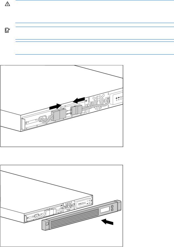
Connect the battery lead to the battery terminal.
Attaching the UPS front bezel
Installation 13
Selecting the UPS voltage configuration
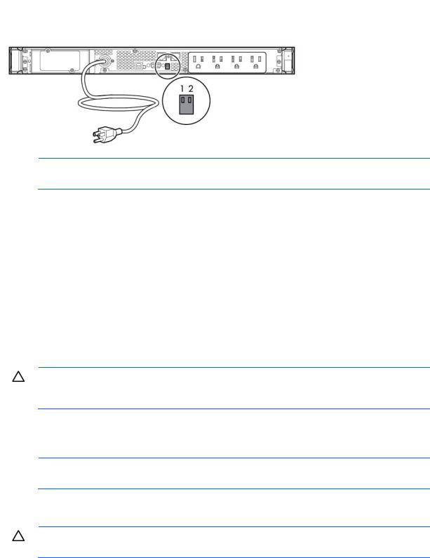
Using a small tool, position the DIP switches according to the desired voltage configuration.
NOTE: An asterisk (*) indicates the default setting.
|
Output voltage |
Input voltage range |
DIP switch 1 |
DIP switch 2 |
|
|
|
|
|
R1500 G3 JPN/TWN |
100 V* |
90–106 V |
Down |
Down |
|
110 V |
99–116 V |
Down |
Up |
|
|
|
|
|
R1500 G3 NA |
110 V |
99–116 V |
Down |
Up |
|
120 V* |
108–127 V |
Up |
N/A |
|
|
|
|
|
R1500 G3 INTL |
220 V |
198–233 V |
Down |
Up |
|
230 V* |
207–243 V |
Up |
N/A |
|
|
|
|
|
|
240 V |
216–254 V |
Down |
Down |
|
|
|
|
|
Connecting the host computer
CAUTION: Only one communications port can be connected to the host computer. Connecting more than one will result in unexpected UPS behavior. If an option card is installed, the serial and USB communications ports are automatically disabled.
Connect the UPS to a host computer using either the USB cable or the DB9 serial cable included with the UPS. Install HP Power Protector on the host computer. See the HP website (http://www.hp.com/go/rackandpower) to download the latest version of HP Power Protector.
NOTE: To install and configure the software, see the software user guide. The software user guide is available for download from the HP website (http://www.hp.com/go/rackandpower).
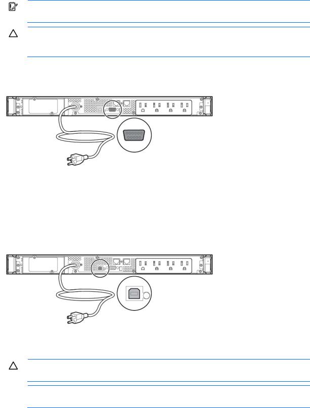
Connecting the serial communications port
CAUTION: Use only the computer interface cable supplied with the UPS to connect the communications port to the host computer.
Installation 14
IMPORTANT: Power protector software requires the communications port to be appropriately cabled to the host computer.
CAUTION: Only one communications port can be connected to the host computer. Connecting more than one will result in unexpected UPS behavior. If an option card is installed, the serial and USB communications ports are automatically disabled.
For information about serial port pin assignment, see "Serial communications port pin assignment (on page 36)" .
Connecting the USB communications port
Connecting the Network Transient Protectors
CAUTION: To avoid damaging the equipment, use the Network Transient Protector with a standard telephone line only, not with a digital PBX.
NOTE: Do not connect any telephone or fax/modem equipment (RJ-11) to the 230V models; only connect network cable (RJ-45) to the 230V models.
To protect equipment against surges over a network data line:
1.Connect the network wall jack to the UPS Network Transient Protector IN jack.
Installation 15
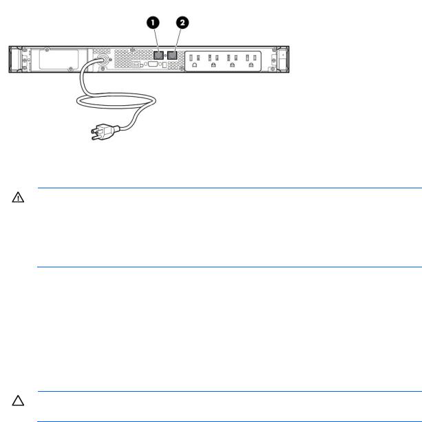
2.Connect the equipment to the UPS Network Transient Protector OUT jack.
Connecting the UPS to utility power
WARNING: To prevent injury from electric shock or damage to the equipment:
•Plug the input line cord into a grounded (earthed) electrical outlet that is installed near the equipment and is easily accessible.
•Do not disable the grounding plug on the input line cord. The grounding plug is an important safety feature.
•Do not use extension cords.
1.Connect the input power cord to the IEC-320-C14 input power connector on the UPS rear panel (INTL model only).
2.Connect the UPS power cord to a grounded utility power outlet. When the UPS is connected, the batteries begin to charge. Power to the output receptacles designated for surge and battery backup is not available until the unit is powered up.
For more information about receptacle control, see "Power protector software (on page 29)" .
Connecting devices to the UPS
CAUTION: Do not plug laser printers into the UPS output receptacles. The instantaneous current drawn by this type of printer can overload the UPS.
Before connecting devices, verify that the UPS will not overload by checking that the ratings of the devices do not exceed the UPS capacity. If the equipment rating is listed in amps, multiply the number of amps by the selected output voltage to determine the VA.
After verifying that the UPS will not overload:
•Connect the device power cords to the output receptacles on the rear panel of the UPS (NA/JPN/TWN model).
-or-
•Connect devices to the output receptacles on the rear panel of the UPS using the jumper cords included with the UPS (INTL model).
Installation 16
Loading...