


 Loading...
HP ProLiant DL180 Generation 5 Server
Software Configuration Guide
Part number: 458197-001
First edition: January 2008
Legal notices
© Copyright 2008 Hewlett-Packard Development Company, L.P.
The information contained herein is subject to change without notice. The only warranties for HP products and services are set forth in the express warranty statements accompanying such products and services. Nothing herein should be construed as constituting an additional warranty. HP shall not be liable for technical or editorial errors or omissions contained herein.
Microsoft, Windows, and Windows NT are U.S. registered trademarks of Microsoft Corporation. Windows Server 2003 is a trademark of Microsoft Corporation. Intel, Pentium, and Itanium are trademarks or registered trademarks of Intel Corporation or its subsidiaries in the United States and other countries. UNIX is a registered trademark of The Open Group.

Contents
System BIOS configuration |
|
System BIOS overview ............................................................................................................................ |
5 |
AMIBIOS software ................................................................................................................................. |
5 |
AMIBIOS Setup Utility............................................................................................................................. |
5 |
Accessing the Setup Utility.................................................................................................................. |
6 |
Navigating through the Setup Utility .................................................................................................... |
6 |
Setup Utility menus ............................................................................................................................ |
8 |
Main Menu ................................................................................................................................. |
8 |
Advanced menu ........................................................................................................................ |
10 |
Boot Menu ................................................................................................................................ |
18 |
Security menu............................................................................................................................ |
18 |
Exit menu.................................................................................................................................. |
21 |
Recording custom Setup values ......................................................................................................... |
21 |
Loading system defaults ................................................................................................................... |
21 |
Clearing CMOS ............................................................................................................................. |
22 |
Power-On Self Test (POST)..................................................................................................................... |
22 |
POST error indicators ...................................................................................................................... |
22 |
Recoverable POST Errors ............................................................................................................ |
23 |
POST-related troubleshooting ............................................................................................................ |
23 |
Reprogramming the BIOS with the crisis recovery jumper .......................................................................... |
24 |
NOS installation |
|
Supported NOS................................................................................................................................... |
25 |
NOS pre-installation procedure.............................................................................................................. |
25 |
Hardware setup .............................................................................................................................. |
25 |
BIOS update .................................................................................................................................. |
26 |
Installing Microsoft Windows NOS ........................................................................................................ |
26 |
Pre-installation instructions ................................................................................................................ |
26 |
Installation flow............................................................................................................................... |
26 |
Section 1. Creating the driver diskettes .............................................................................................. |
26 |
Section 2. Installing Windows NOS .................................................................................................. |
27 |
Section 3. Completing the installation ................................................................................................ |
28 |
Phase 1 - Installing the chipset driver ............................................................................................ |
28 |
Phase 2 - Installing the HP network driver ...................................................................................... |
28 |
Phase 3 - Installing the embedded video driver .............................................................................. |
29 |
Section 4. Configuring the system ..................................................................................................... |
29 |
Phase 1 - Performing a hardware status check ............................................................................... |
29 |
Phase 2 - Initializing the hard drive .............................................................................................. |
30 |
Phase 3 - Adding Windows Terminal Services ............................................................................... |
30 |
Section 5. Configuring the network ................................................................................................... |
31 |
Phase 1 - Configuring the server’s IP address................................................................................. |
31 |
Phase 2 - Attaching clients to the network and testing the network link .............................................. |
31 |
Phase 3 - Configuring the domain controller setup.......................................................................... |
32 |
Section 6. Installing additional HP accessories .................................................................................... |
33 |
Installing Red Hat Enterprise Linux NOS.................................................................................................. |
33 |
Installation flow............................................................................................................................... |
33 |
Pre-installation instructions ................................................................................................................ |
33 |
|
3 |
Contents |
|
Red Hat Enterprise Linux 4 and 5 installation ...................................................................................... |
34 |
Section 1. Launching the Red Hat Enterprise Linux installer .............................................................. |
34 |
Section 2. Customizing the installation.......................................................................................... |
34 |
Section 3. Installing Red Hat Enterprise Linux 4 and 5 .................................................................... |
35 |
Section 4. Configuring the initial setup settings .............................................................................. |
35 |
Installing SUSE Linux Enterprise Server NOS............................................................................................ |
36 |
Installation flow............................................................................................................................... |
36 |
Pre-installation instructions ................................................................................................................ |
36 |
SUSE Linux Enterprise Server 9 installation ......................................................................................... |
37 |
Section 1. Installing SUSE Linux Enterprise Server 9........................................................................ |
37 |
Section 2. Customizing the installation.......................................................................................... |
37 |
Section 3. Completing the installation ........................................................................................... |
37 |
SUSE Linux Enterprise Server 10 Installation ....................................................................................... |
38 |
Section 1. Installing SUSE Linux Enterprise Server 10...................................................................... |
38 |
Section 2. Customizing the Installation.......................................................................................... |
38 |
Section 3. Completing the installation ........................................................................................... |
39 |
Installing Sun Solaris 10 ....................................................................................................................... |
39 |
Pre-installation instructions ................................................................................................................ |
39 |
Installation flow............................................................................................................................... |
40 |
Sun Solaris 10 installation................................................................................................................ |
40 |
Section 1. Launching the Sun Solaris10 installer............................................................................. |
40 |
Section 2. Customizing the installation.......................................................................................... |
40 |
Section 3. Completing the installation ........................................................................................... |
41 |
Server management |
|
Preand post-installation procedures ....................................................................................................... |
43 |
Pre-installation procedures................................................................................................................ |
43 |
Post-installation procedures............................................................................................................... |
43 |
Configuring the BMC ........................................................................................................................... |
43 |
Index |
|
4

System BIOS configuration
This chapter describes the basic functions of the AMIBIOS software.
System BIOS overview
A Basic Input/Output System, or BIOS, is a set of programs permanently stored in an EEPROM chipset located on the system board. These programs serve as an interface between the server’s hardware components and its operating system. This ProLiant server features the AMIBIOS software—a ROM BIOSbased diagnostic tool that monitors system activity and performs constant hardware testing to ensure proper system operation.
AMIBIOS software
The AMIBIOS software serves three functions:
•Configure the system settings via the AMIBIOS Setup Utility
Using the Setup Utility, you can install, configure, and optimize the hardware devices on your system (such as clock, memory, and hard drives).
•Initialize hardware at boot via POST routines
At power-on or reset, the software performs Power-On Self Test (POST) routines to test system resources and run the operating system.
•Perform run-time routines
Using the software, perform basic hardware routines that can be called from OS-based applications.
AMIBIOS Setup Utility
NOTE: For ease of reading, the AMIBIOS Setup Utility will be referred to as “Setup” or “Setup Utility” in this guide. Also, the screenshots used in this guide display default system values. These values may not be the same as those in your server.
The AMIBIOS Setup Utility is a hardware configuration program built into the server BIOS. Because most systems are already properly configured and optimized, there is normally no need to run this utility.
You need to run this utility under the following conditions:
•When changing the system configuration, including:
○Setting the system time and date
○Configuring the hard drives
○Specifying the boot device sequence
○Configuring the power management modes
○Setting up system passwords or making other changes to the security setup
5

System BIOS configuration
•When a configuration error is detected by the system and you are prompted by a "Run Setup" message to make changes to the BIOS settings.
NOTE: If you repeatedly receive “Run Setup” messages, the battery located on the system board may be defective. In this case, the system cannot retain configuration values in CMOS. Ask a qualified technician for assistance.
The Setup Utility loads the configuration values in a battery-backed nonvolatile memory called CMOS RAM. This memory area is not part of the system RAM, which allows configuration data to be retained when power is turned off. The values take effect when the system is booted. POST uses these values to configure the hardware. If the values and the actual hardware do not agree, POST generates an error message. You must run the Setup Utility to change the BIOS settings from the default or current configuration.
Accessing the Setup Utility
1.Turn on the monitor and the server.
If the server is already turned on, save your data and exit all open applications, then restart the server.
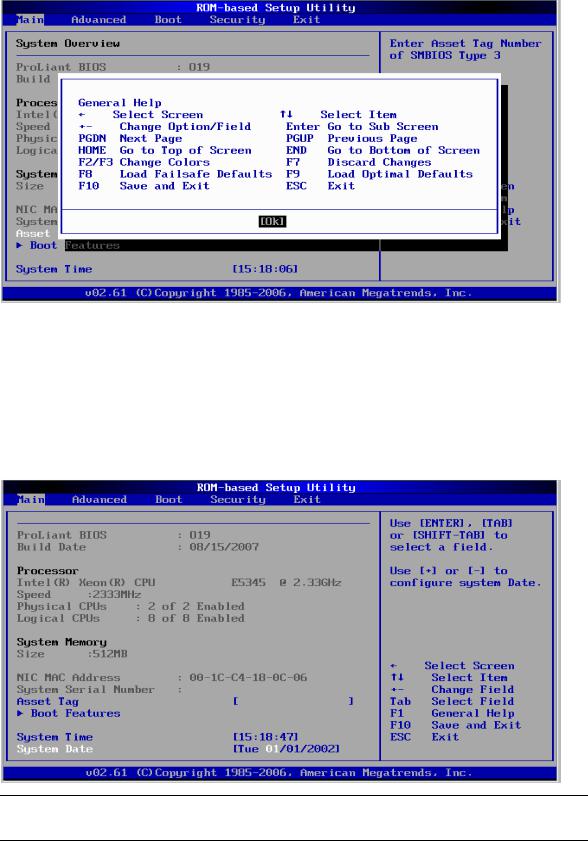
During POST, press F10. If you fail to press F10 before POST is completed, you need to restart the server and repeat this step. The first page displayed is the Main menu. Use the left (←) and right (→) arrow keys to move between selections on the menu bar.
Figure 1 Main menu
NOTE: System Serial Number and Asset Tag are not updated even when CMOS defaults are loaded or CMOS is cleared.
Navigating through the Setup Utility
Use the keys listed in the legend bar on the bottom of the Setup screen to access the various menu and submenu screens of the Setup Utility. Figure 1 in the previous section shows the legend bar at the bottom
6

System BIOS configuration
of the Main menu. Table 1 Setup Utility navigation keys lists these legend keys and their respective functions.
Table 1 Setup Utility navigation keys
Key Function
← and →
↑ and ↓
Move between selections on the menu bar.
Move the cursor to the field you want.
The currently selected field is highlighted. The right side of each menu screen displays the Item Specific Help panel. This panel displays the help text for the selected field. It updates as you move the cursor to each field.
<+>, <–> |
Select a value for the currently selected field if it is user-configurable. |
|
Press the (+) or (-) keys repeatedly to scroll through each value one at a time, or press the Enter key to |
|
choose from a pop-up menu that displays all possible values at once. |
|
A parameter that is enclosed in square brackets [ ] is user-configurable. |
|
Grayed-out parameters are not user-configurable for one of the following reasons: |
|
• The field value is auto-configured or auto-detected. |
|
• The field value is informational only. |
|
• The field is password-protected. |
|
|
Enter |
Select a field value or display a submenu screen. |
►Indicates a submenu field.
To view a submenu screen, use the ↑ and ↓ keys to move the cursor to the submenu you want, then press Enter.
Esc |
|
When you press this key: |
|
|
• On a primary menu screen, the Exit menu displays. |
|
|
• On a submenu screen, the previous screen displays. |
|
|
• On a pop-up menu, closes the pop-up without making a selection. |
|
|
|
F1 |
|
Displays the General Help window. See Figure 2. The General Help window describes other Setup |
|
|
navigation keys that are not displayed on the legend bar. |
|
|
|
F9 |
|
Loads the default system values. |
|
|
|
F10 |
|
Saves all changes to settings and closes the Setup Utility. |
|
|
|
7
System BIOS configuration
Figure 2 General Help Screen
Setup Utility menus
The Setup Utility menu bar displays the five primary menu selections. For detailed information and screenshots of these Setup menus and their related submenus, refer to the following sections.
Main Menu
Figure 3 Main Menu
NOTE: The time is in 24-hour format. For example, 5:30 A.M. appears as 05:30:00, and 5:30 P.M. as 17:30:00. If you clear CMOS, setup time and date values will be BIOS release date.
8

System BIOS configuration
Table 2 Main menu fields
Field |
|
Description |
|
|
|
System Overview |
|
Displays the system ROM version, the date when the Setup utility was created and |
|
|
identification number. |
|
|
|
Processor |
|
Displays the CPU type, speed and count. |
|
|
|
System Memory |
|
Displays the amount of conventional memory detected. |
|
|
|
Asset Tag |
|
Enter the server asset tag. |
|
|
|
System Serial |
|
Enter the server serial number. The serial number is indicated on the serial number label pull |
Number |
|
tab on the front panel. |
|
|
|
System Time |
|
Adjusts the system time. |
|
|
|
System Date |
|
Adjusts the system date. |
|
|
|
Boot Features |
|
Sets which options to run during system boot up. Press Enter to access the related submenu. |
|
|
For details on the submenu options, see the “Boot Features submenu” section. |
|
|
|
Boot Settings Configuration submenu
Figure 4 Boot Features submenu
Table 3 Boot Features fields
Field |
Description |
Options |
|
|
|
Quick Boot |
Set this value to allow BIOS to skip certain tests while booting. This will decrease |
Enabled |
|
the time needed to boot the system. |
|
|
|
|
9
System BIOS configuration
Table 3 Boot Features fields
Field |
Description |
Options |
|
|
|
Resume On LAN |
Set this value to allow system wake up on LAN from Hibernation. |
Enabled |
|
|
|
|
Cannot wake up the system from Hibernation if set to Disabled |
Disabled |
|
|
|
Bootup Num- |
Set this value to allow Num Lock on the keyboard to be enabled automatically |
Enabled |
Lock |
when the computer system boots up. This allows the immediate use of the numeric |
|
|
keypad located on the right side of the keyboard. To confirm this, the Num Lock |
|
|
LED on the keyboard will be on. This is the default setting. |
|
|
|
|
|
This option does not enable the keyboard Num Lock automatically. To use the |
Disabled |
|
numeric keypad, need press the “Num Lock” key located on the upper left-hand |
|
|
corner of the numeric keypad. The Num Lock LED on the keyboard will be on |
|
|
when Num lock is engaged. |
|
|
|
|
Restore on AC |
Set this value to restores previous power state before loss occurred. |
Last State |
Power Loss |
|
|
|
|
|
|
Set this value to let system always boot up automatically when AC power is |
Power on |
|
restored. |
|
|
|
|
|
Set this value not to boot up the system until the power button is pressed. |
Stay Off |
|
|
|
POST F1 Prompt |
Set this value to let system wait up to 15 seconds to continue in case POST errors |
Delayed |
|
detected, or press F1to skip it. |
|
|
|
|
|
Set this value to wait indefinitely for an F1 press. |
Enabled |
|
|
|
|
Set this value to boot without waiting for an F1 press. |
Disabled |
|
|
|
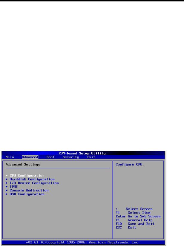
Advanced menu
Figure 5 Advanced menu
10
System BIOS configuration
NOTE: The CPU Configuration setup screen varies depending on the installed processor.
Table 4 Advanced menu fields
Field |
Description |
||
|
|
|
|
CPU Configuration |
Use this screen to select options for the CPU Configuration Settings. |
||
|
|
|
|
Harddisk |
Use this screen to select options for the Harddisk Configuration Settings. |
||
Configuration |
|
||
|
|
|
|
I/O Device |
Use this screen to select options for the I/O device configuration settings. Use the up and down |
||
Configuration |
<Arrow> keys to select an item. Use the <Plus> and <Minus> keys to change the value of the |
||
|
|
selected option. The settings are described on the following pages. |
|
|
|
|
|
IPMI |
Select this option to view the contents of IPMI. A delay may be noticed when selecting IPMI, |
||
|
|
||
|
|
due to the time required for retrieval of sensor data. |
|
|
|
|
|
Console |
Configuration options for Console redirection. |
||
Redirection |
|||
|
|||
|
|
|
|
USB Configuration |
Configuration options for the system USB controller. |
||
|
|
|
|
CPU Configuration submenu
Figure 6 CPU Configuration submenu
11
System BIOS configuration
Table 5 CPU Configuration submenu fields
Field |
Description |
Options |
|
|
|
Core Multi-processing |
Set this value to support multi-core processor. The optimal and setup |
Enabled |
|
default setting is Enabled. |
|
|
|
|
|
This setting configures single logical option processor mode; Only core 0, |
Disabled |
|
logical processor 0 remains active. |
|
|
|
|
Intel(R) SpeedStep (tm |
This setting is available if the processor supports SpeedStep. Enabling this |
Enabled |
Tech) |
value will let CPU run at appropriate speed and voltage as determined |
|
|
by the OS per system requirements. |
|
|
|
|
|
Disabling SpeedStep ensures that the CPU will run at maximum speed. |
Disabled |
|
|
|
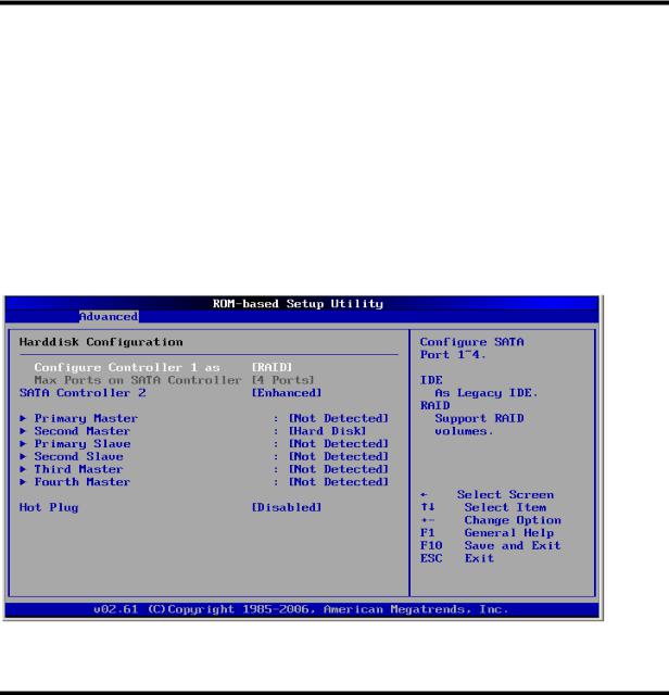
Harddisk Configuration submenu
Figure 7 Harddisk Configuration submenu
Table 6 Harddisk Configuration submenu fields
Field |
Description |
Options |
|
|
|
Configure SATA #1 as |
Set this option to support RAID (Redundant Array of Independent |
RAID |
|
|
|
|
Disks) technology, the optimal and default setting is disabled. |
|
|
|
|
|
Enhanced (non-AHCI and non-RAID) mode, SATA drives are auto- |
IDE |
|
detected and placed in Native IDE mode. |
|
|
|
|
Hot Plug |
Set this value to allow the hard disk drive to be used normally. Read, |
Disabled |
|
write, and erase functions can be performed to the hard disk drive. This |
|
|
is the default setting. |
|
|
|
|
12

System BIOS configuration
Table 6 Harddisk Configuration submenu fields
Field |
Description |
Options |
|
|
|
|
Set this value to prevent the hard disk drive from being erased. |
Enabled |
|
|
|
I/O Device Configuration submenu
Figure 8 I/O Device Configuration submenu
Table 7 I/O Device Configuration submenu fields
Option |
|
Description |
|
|
|
|
|
Disabled |
|
Set this value to prevent the serial port from accessing any system resources. When this option is |
|
|
|
|
set to Disabled, the serial port physically becomes unavailable |
|
|
|
|
3F8/IRQ4 |
|
Set this value to allow the serial port to use 3F8 as its I/O port address and IRQ 4 for the interrupt |
|
|
|
|
address. This is the default setting. The majority of serial port 1 or COM1 ports on computer |
|
|
|
systems use IRQ4 and I/O Port 3F8 as the standard setting. The most common serial device |
|
|
|
connected to this port is a mouse. If the system will not use a serial device, it is best to set this port |
|
|
|
to Disabled. |
|
|
|
|
3E8/IRQ4 |
|
Set this value to allow the serial port to use 3E8 as its I/O port address and IRQ 4 for the interrupt |
|
|
|
|
address. If the system will not use a serial device, it is best to set this port to Disabled. |
|
|
|
|
2E8/IRQ3 |
|
Set this value to allow the serial port to use 2E8 as its I/O port address and IRQ 3 for the interrupt |
|
|
|
|
address. If the system will not use a serial device, it is best to set this port to Disabled. |
|
|
|
|
2F8/IRQ3 |
|
Set this value to allow the serial port to use 2F8 as its I/O port address and IRQ 3 for the interrupt |
|
|
|
|
address. If the system will not use a serial device, it is best to set this port to Disabled |
|
|
|
|
13

System BIOS configuration
IPMI Configuration submenu
Figure 9 IPMI Configuration submenu
Table 8 IPMI Device Configuration submenu fields
Field |
Description |
|
|
System Event Logging |
Select to enable/disable IPMI event logging. Disabling will still log events received via the |
|
system interface. |
|
|
Event Log Control |
Select to control event log configuration, from this configuration screen. |
|
|
BIOS Post Watchdog |
Select to enable POST watchdog. |
|
|
OS Boot Watchdog |
Select to enable OS boot watchdog. |
|
14 |
|
Loading...