


HP Rack and Power Manager
User Guide
January 2004 (Second Edition)
Part Number 311371-002
©Copyright 2003, 2004 Hewlett-Packard Development Company, L.P.
©1999, 2000 GoAhead Software, Inc. All rights reserved.
©1995-1998 Eric Young (eay@cryptsoft.com). All rights reserved
©1998-2003 The OpenSSL Project
Confidential computer software. Valid license from HP required for possession, use or copying. Consistent with FAR 12.211 and 12.212, Commercial Computer Software, Computer Software Documentation, and Technical Data for Commercial Items are licensed to the U.S. Government under vendor’s standard commercial license.
The information contained herein is subject to change without notice. The only warranties for HP products and services are set forth in the express warranty statements accompanying such products and services. Nothing herein should be construed as constituting an additional warranty. HP shall not be liable for technical or editorial errors or omissions contained herein.
Microsoft, Windows, and Windows NT are U.S. registered trademarks of Microsoft Corporation. Linux is a U.S. registered trademark of Linus Torvalds.
Intel and Pentium are trademarks or registered trademarks of Intel Corporation or its subsidiaries in the United States and other countries.
JavaTM is a U.S. trademark of Sun Microsystems, Inc.
This product includes software developed by the OpenSSL Project for use in the OpenSSL Toolkit (http://www.openssl.org/).
Printed in the U.S.A.
HP Rack and Power Manager User Guide
January 2004 (Second Edition)
Part Number 311371-002

Contents
About This Guide
Audience Assumptions............................................................................................................................... |
vii |
Symbols in Text.......................................................................................................................................... |
vii |
Text Conventions ....................................................................................................................................... |
vii |
Related Documents.................................................................................................................................... |
viii |
Getting Help .............................................................................................................................................. |
viii |
Technical Support ............................................................................................................................... |
viii |
HP Website ......................................................................................................................................... |
viii |
Authorized Reseller ............................................................................................................................... |
ix |
Reader’s Comments ..................................................................................................................................... |
ix |
Chapter 1
Overview
Introduction ............................................................................................................................................... |
1-1 |
HP Rack and Power Manager Overview................................................................................................... |
1-3 |
HP Rack and Power Manager Architecture ........................................................................................ |
1-4 |
Supported Hardware Configurations .................................................................................................. |
1-8 |
Power Protection for the Rack and Power Management Server ....................................................... |
1-18 |
Chapter 2
Installation
System Requirements ................................................................................................................................ |
2-1 |
Browser Requirements........................................................................................................................ |
2-4 |
Installation Overview ................................................................................................................................ |
2-4 |
Installing Components on Windows Operating Systems .......................................................................... |
2-5 |
Installing the Components Using the GUI Installation Method.......................................................... |
2-5 |
Installing the System Agent and Serial Relay Agent Using the Silent Installation Method............. |
2-17 |
Installing Components on Linux Operating Systems .............................................................................. |
2-19 |
Installing the Components Using the GUI Installation Method........................................................ |
2-19 |
Installing the System Agent and Serial Relay Agent Using the Silent Installation Method............. |
2-32 |
Installing Components on NetWare Operating Systems ......................................................................... |
2-34 |
Installing the Components Using the GUI Installation Method........................................................ |
2-34 |
Installing the System Agent and Serial Relay Agent Using the Silent Installation Method............. |
2-45 |
Upgrading From HP Rack and Power Manager 1.0................................................................................ |
2-46 |
Upgrading Components on Windows Systems Using the GUI Method........................................... |
2-47 |
Upgrading Components on Windows Systems Using the Silent Method......................................... |
2-48 |
Upgrading Components on Linux Systems Using the GUI Method................................................. |
2-49 |
Upgrading Components on Linux Systems Using the Silent Method .............................................. |
2-50 |
HP Rack and Power Manager User Guide |
iii |

Contents
Upgrading Components on NetWare Systems |
Using the GUI Method ............................................ |
2-51 |
Upgrading Components on NetWare Systems Using the Silent Method .......................................... |
2-52 |
|
Uninstalling Components from Windows Systems |
................................................................................. |
2-54 |
Uninstalling Components from Linux Systems ....................................................................................... |
|
2-54 |
Uninstalling Components from NetWare Systems .................................................................................. |
|
2-55 |
Chapter 3
Access and Navigation
Browsing to HP Rack and Power Manager ............................................................................................... |
3-1 |
Browsing Remotely............................................................................................................................. |
3-1 |
Browsing Locally ................................................................................................................................ |
3-2 |
Regarding the Browser Security Alert ....................................................................................................... |
3-3 |
Establishing a Secure Session for Internet Explorer ........................................................................... |
3-3 |
Establishing a Secure Session for Mozilla .......................................................................................... |
3-4 |
Logging Into HP Rack and Power Manager .............................................................................................. |
3-5 |
Navigating HP Rack and Power Manager ................................................................................................. |
3-5 |
Chapter 4
Configuration
Settings Tab ............................................................................................................................................... |
4-1 |
Automatic Discovery Screen............................................................................................................... |
4-2 |
Manual Discovery Screen.................................................................................................................... |
4-4 |
Discovery Results Screen .................................................................................................................... |
4-7 |
Device Management Screen ................................................................................................................ |
4-8 |
Agent Management Screen................................................................................................................ |
4-10 |
User Administration Screen .............................................................................................................. |
4-13 |
My Account Screen ........................................................................................................................... |
4-15 |
Notification Recipients Screen .......................................................................................................... |
4-16 |
Session Management Screen ............................................................................................................. |
4-20 |
System Logs Screen .......................................................................................................................... |
4-21 |
Database Screen ................................................................................................................................ |
4-22 |
Email Server Setup Screen ................................................................................................................ |
4-23 |
Configuration Screen......................................................................................................................... |
4-24 |
About RPM Screen............................................................................................................................ |
4-25 |
Chapter 5
Operation
Devices Tab ............................................................................................................................................... |
5-1 |
Devices Home Screen ................................................................................................................................ |
5-2 |
CMC Devices............................................................................................................................................. |
5-2 |
Device Overview Screen ..................................................................................................................... |
5-3 |
Logs and Reports Screen ..................................................................................................................... |
5-5 |
Sensor Setup Screen ............................................................................................................................ |
5-7 |
Accessory Setup Screen ...................................................................................................................... |
5-9 |
Event Response Overview Screen..................................................................................................... |
5-12 |
Properties Screen............................................................................................................................... |
5-17 |
Manual Control Screen...................................................................................................................... |
5-19 |
iv |
HP Rack and Power Manager User Guide |

|
Contents |
UPS Devices............................................................................................................................................ |
5-20 |
Device Overview Screen................................................................................................................... |
5-21 |
Logs and Reports Screen .................................................................................................................. |
5-23 |
Attached Agents Screen.................................................................................................................... |
5-25 |
Power Fail Settings Screen ............................................................................................................... |
5-26 |
Scheduled Shutdowns Screen ........................................................................................................... |
5-30 |
Event Response Overview Screen .................................................................................................... |
5-32 |
Properties Screen .............................................................................................................................. |
5-37 |
Diagnostics Screen............................................................................................................................ |
5-38 |
Manual Control Screen ..................................................................................................................... |
5-39 |
Agents Tab .............................................................................................................................................. |
5-40 |
Managed Agents Screen ................................................................................................................... |
5-41 |
Queries Tab ............................................................................................................................................. |
5-42 |
Queries Screen .................................................................................................................................. |
5-42 |
Home Tab ................................................................................................................................................ |
5-44 |
Home Screen..................................................................................................................................... |
5-44 |
Chapter 6 |
|
Troubleshooting |
|
Appendix A |
|
Alert Messages |
|
Appendix B |
|
Using HP Rack and Power Manager with HP Systems Insight Manager |
|
Discovering HP Rack and Power Manager ............................................................................................... |
B-1 |
Receiving SNMP Traps............................................................................................................................. |
B-2 |
Launching HP Rack and Power Manager from the HPSIM Tools Menu ................................................. |
B-3 |
Appendix C |
|
Using HP Rack and Power Manager with HP Insight Manager 7 SP2 |
|
Configuring Insight Manager 7 SP2.......................................................................................................... |
C-1 |
Configuring HP Rack and Power Manager ............................................................................................... |
C-1 |
Appendix D
Backing Up and Restoring Rack and Power Manager
Appendix E
HP Rack and Power Manager Security Considerations
Index
HP Rack and Power Manager User Guide |
v |

About This Guide
This guide provides information about HP Rack and Power Manager including installation, configuration, operation, and troubleshooting.
Audience Assumptions
This guide is intended for individuals requiring information about the management of HP Uninterruptible Power Systems (UPSs) and Console Management Controllers (CMCs).
Symbols in Text
These symbols are found in the text of this guide. They have the following meanings:
CAUTION: Text set off in this manner indicates that failure to follow directions could result in damage to equipment or loss of information.
IMPORTANT: Text set off in this manner presents clarifying information or specific instructions.
NOTE: Text set off in this manner presents commentary, sidelights, or interesting points of information.
Text Conventions
This document uses the following conventions:
•Italic type indicates complete titles of manuals or variables. Variables include information that varies in system output, command lines, and command parameters in text.
•Bold type is used for emphasis of selected on-screen elements (menu options, command names, dialog box names, and so on) and keyboard keys.
•Monospace typeface indicates code examples, screen displays, and user input.
•Sans serif typeface is used for uniform resource locators (URLs).
HP Rack and Power Manager User Guide |
vii |

About This Guide
Related Documents
For additional information on the topics covered in this guide, refer to the following documents:
•Product user guides
•Product installation instructions
•HP Power Products Glossary
These documents are located on the Power Products Documentation CD or at
http://www.hp.com/products/ups.
Getting Help
If you have a problem and have exhausted the information in this guide, you can get further information and other help in the following locations.
Technical Support
In North America, call the HP Technical Support Phone Center at 1-800-652-6672. This service is available 24 hours a day, 7 days a week. For continuous quality improvement, calls may be recorded or monitored. Outside North America, call the nearest HP Technical Support Phone Center. For telephone numbers of worldwide Technical Support Centers, go to http://www.hp.com.
Have the following information available before you call:
•Technical support registration number (if applicable)
•Product serial number
•Product model name and number
•Applicable error messages
•Add-on boards or hardware
•Third-party hardware or software
•Operating system type and revision level
•Power management software type and version
HP Website
For information on this product as well as the latest drivers, firmware updates, and service packs, go to http://www.hp.com.
viii |
HP Rack and Power Manager User Guide |

About This Guide
Authorized Reseller
For the name of your nearest authorized reseller:
•In the United States, call 1-800-345-1518.
•In Canada, call 1-800-263-5868.
•Elsewhere, see the HP website for locations and telephone numbers.
Reader’s Comments
To comment on this guide, send an e-mail to ServerDocumentation@hp.com.
HP Rack and Power Manager User Guide |
ix |

1
Overview
Introduction
HP Rack and Power Manager is enterprise-grade software that enables users to monitor, manage, and control both power and rack environments through comprehensive control of HP Uninterruptible Power Systems (UPSs) and the HP rack environmental monitor, the Console Management Controller (CMC). HP Rack and Power Manager software provides comprehensive device control in data center environments where multiple users need to access and manage many devices. A familiar browser interface provides secure remote access (128-bit Secure Socket Layer (SSL) encryption) to management agents anywhere on the network. HP Rack and Power Manager enables users to schedule system shutdowns, control power failure settings, and define UPS load segments to allow for maximum uptime of critical servers. This software offers several new features, such as the ability to configure redundant UPSs and system event handling, which enables users to establish power and environmental failure policies with programmed automatic responses.
Use HP Rack and Power Manager to monitor, manage, and control:
•HP Tower UPSs—UPS T700, UPS T1000 XR, UPS T1500 XR, and UPS T2200 XR
•HP Rack UPSs—UPS R1500 XR, UPS R3000 XR, UPS R5500 XR, UPS R6000, and UPS R12000 XR
•HP CMCs—Rack environmental monitoring devices
HP Rack and Power Manager software can run as a stand-alone power management system or be configured to run with other SNMP-management programs:
•HP Rack and Power Manager can be configured as a plug-in for HP Systems Insight Manager. For more information, refer to Appendix B in this guide.
•HP Rack and Power Manager can send traps with a URL to HP Insight Manager 7. For more information, refer to Appendix C in this guide.
This flexibility enables you to monitor, manage, and control the rack and power environments of networked and serially-attached devices (CMCs and UPSs), regardless of the system management method. For ease of configuration, HP Rack and Power Manager can be configured to perform device auto-discovery and to copy alert notifications of already managed devices to newly managed devices. To facilitate day-to-day maintenance tasks, the software provides detailed system logs and system diagnostics, including UPS battery checks.
HP Rack and Power Manager User Guide |
1-1 |
Overview
Use HP Rack and Power Manager to:
•Customize alerts
—Send e-mail notification messages
—Send broadcast notification messages
—Send SNMP traps
—Issue computer commands
—Perform device actions
•Monitor, manage, and control UPSs
—Configure redundant UPSs to support servers with multiple power supplies
—Manage a graceful shutdown of attached equipment during utility power failures
—Manage independent UPS load segments to provide separate power control of connected equipment
—Prioritize the timing of equipment shutdowns and reboot connected equipment by load segment
—Shut down and reboot any UPS and attached equipment, based on a user-specified schedule
—Delay restart by load segment after a power outage to sequence the startup of system components
—Display UPS logs for analysis
—Monitor the status of UPSs and perform UPS diagnostics
•Monitor, manage, and control CMCs
—Configure and monitor the CMC sensors and options (air temperature, shock/vibration, humidity, intrusion, smoke detection, and front and back door locks)
—Activate relay controls
—Display CMC logs for analysis
—Remotely or locally monitor and control rack environments
—Take action when a negative occurrence is taking place
1-2 |
HP Rack and Power Manager User Guide |

Overview
HP Rack and Power Manager Overview
HP Rack and Power Manager is a Web-based application that lets administrators manage large numbers of devices (HP UPSs and CMCs) in the data center from a single management console. Administrators can monitor, manage, and control devices both locally and remotely through a secure browser interface.
Example 1-1: During a utility power failure, the connected UPSs switch to battery mode. HP Rack and Power Manager can issue an e-mail alert to the system administrator and begin a prioritized system shutdown based on your settings. After power is restored, HP Rack and Power Manager can facilitate a prioritized power up for connected equipment. HP Rack and Power Manager also allows for scheduled on and off times, which promotes power conservation.
The UPS can be configured to extend runtimes for critical devices during utility power failures. For most UPSs, the receptacles on the rear panel can be divided into two or more groups, called load segments, which can be controlled independently. By shutting down a load segment that is connected to less critical equipment, the runtime for more critical equipment is extended, providing additional protection.
Example 1-2: HP Rack and Power Manager has the ability to issue commands to servers that the software recognizes. Issuing commands can be a useful tool in preventing data loss. If a CMC detects an over temperature event or a UPS detects a utility power failure event, the HP Rack and Power Management Server can be configured to issue a command to run a batch file or shell script on the affected system.
Example 1-3: HP Rack and Power Manager can be configured to monitor set thresholds for CMC sensors and take action when conditions are detected to be outside the threshold. HP Rack and Power Manager can be programmed to turn the rack fans on when the rack temperature is too warm or turn the rack fans off if smoke is detected. Should an unauthorized person attempt to enter the rack, HP Rack and Power Manager can send an alert message to the system administrator and activate an alarm relay switch that can be connected to a siren or rotating light.
Example 1-4: HP Rack and Power Manager can be configured to take action on multiple devices based on an event of a single device. If a CMC installed in a rack on the ninth floor detects an over temperature condition, HP Rack and Power Manager can be configured to send a message to the UPS powering the affected equipment and gracefully shut down the servers installed in the rack. The same is true for UPSs. If a UPS in the same rack loses utility power and goes on battery, the Management Server can be configured to send a message to the CMC installed in that same rack to unlock the rack door.
HP Rack and Power Manager User Guide |
1-3 |

Overview
HP Rack and Power Manager Architecture
HP Rack and Power Manager leverages a distributed architecture that consists of three major components:
•Management Server
•System Agent
•Serial Relay Agent
Figure 1-1: HP Rack and Power Manager architecture
Item Description
1HP Rack and Power Management Server*
2A remote workstation browsing in to the Management Server over the network
3A management application, such as HP Systems Insight Manager or HP OpenView, on a remote workstation that is receiving SNMP traps from the Management Server over the network
4A UPS that is powering multiple servers and communicating with a Management Server through a serial connection to one of the servers
5Servers on the network that are running HP Rack and Power Management Agents receive custom commands from the Management Server
6A UPS that is providing power to multiple servers and communicating directly with the Management Server over the network
7CMCs that are attached to the network are managed by the Management Server
*A dedicated Management Server is not required.
1-4 |
HP Rack and Power Manager User Guide |

Overview
Management Server
The Management Server component runs on a single server, which acts as the management console. The Management Server communicates with discovered and managed CMCs and UPSs throughout the network. The Management Server continuously polls devices for status. When an alert is detected, the Management Server acts on configured event policies.
IMPORTANT: UPS and CMC devices should be managed by a single Management Server. It is not necessary to have a dedicated server running the Management Server component. Any machine with the available resources can be used.
Additional features of the Management Server include:
•Polling the network for supported UPSs, CMCs, and System Agents (automatic discovery)
•Controlling security and authentication
—Individual logon accounts
—SSL implemented
•Generating status and configuration pages for authenticated users connecting through a Web browser
•Generating commands to send to the System Agents to prepare for, initiate, and cancel tasks
•Notifying administrators of alerts by way of e-mails, e-mail pages, and pop-up messages
•Sending alert traps to Insight Manager and other manageability software programs that receive SNMP traps
The Management Server operates on a single server that is running any of the following operating systems:
•Microsoft® Windows NT® 4.0 Server with Service Pack 6
•Microsoft Windows® 2000 Server with Service Pack 4
•Microsoft Windows 2000 Advanced Server with Service Pack 4
•Microsoft Windows 2003 Standard Server
•Microsoft Windows 2003 Enterprise Edition
•Red Hat Linux® 7.3 Server with Errata Kernel 2.4.20-18
•Red Hat Linux 8.0 Server with Errata Kernel 2.4.20-18
•Red Hat Enterprise Linux WS/ES/AS 2.1 with Errata Kernel 2.4.9-e.25
•UnitedLinux 1.0 with Errata Kernel sp2a
NOTE: Conectiva Linux Enterprise Edition, SCO Linux 4.0, SUSE Linux Enterprise 8, and
Turbolinux 8 are all powered by UnitedLinux 1.0.
HP Rack and Power Manager User Guide |
1-5 |

Overview
System Agent
The System Agent is the software component that runs on a server and allows HP Rack and Power Manager to gracefully shut down the operating system of that server or take another pre-configured action in case of a specific event.
IMPORTANT: Install the System Agent on any server that is attached to a UPS and on any server that HP Rack and Power Manager uses to initiate a command. For more information on using commands, refer to “Commands Tab” i n Chapter 5.
A server that has the System Agent installed is discovered and recognized by HP Rack and Power Manager as an agent. Agents can be associated with one or more UPSs or UPS load segments. For more information on associating agents, refer to “Attached Agents Screen” in Chapter 5.
The System Agent operates on any network-connected server that is running one of the following operating systems:
•Microsoft Windows NT 4.0 Server with Service Pack 6
•Microsoft Windows 2000 Server with Service Pack 4
•Microsoft Windows 2000 Advanced Server with Service Pack 4
•Microsoft Windows 2003 Standard Server
•Microsoft Windows 2003 Enterprise Edition
•Novell NetWare 5.1 with Support Pack 6
•Novell NetWare 6.0 with Support Pack 3
•Red Hat Linux 7.3 Server with Errata Kernel 2.4.20-18
•Red Hat Linux 8.0 Server with Errata Kernel 2.4.20-18
•Red Hat Enterprise Linux WS/ES/AS 2.1 with Errata Kernel 2.4.9-e.25
•UnitedLinux 1.0 with Errata Kernel sp2a
NOTE: Conectiva Linux Enterprise Edition, SCO Linux 4.0, SUSE Linux Enterprise 8, and
Turbolinux 8 are all powered by UnitedLinux 1.0.
1-6 |
HP Rack and Power Manager User Guide |

Overview
Serial Relay Agent
The Serial Relay Agent is the software component that runs on a server and allows HP Rack and Power Manager to communicate with a UPS that is serially attached to a network-connected server. A server that has the Serial Relay Agent installed is discovered and recognized by HP Rack and Power Manager as a device with the IP address of the server running the Serial Relay Agent.
The Serial Relay Agent operates on any network-connected server that is serially attached to a UPS and running one the following operating systems:
•Microsoft Windows NT 4.0 Server with Service Pack 6
•Microsoft Windows 2000 Server with Service Pack 4
•Microsoft Windows 2000 Advanced Server with Service Pack 4
•Microsoft Windows 2003 Standard Server
•Microsoft Windows 2003 Enterprise Edition
•Novell NetWare 5.1 with Support Pack 6
•Novell NetWare 6.0 with Support Pack 3
•Red Hat Linux 7.3 Server with Errata Kernel 2.4.20-18
•Red Hat Linux 8.0 Server with Errata Kernel 2.4.20-18
•Red Hat Enterprise Linux WS/ES/AS 2.1 with Errata Kernel 2.4.9-e.25
•UnitedLinux 1.0 with Errata Kernel sp2a
NOTE: Conectiva Linux Enterprise Edition, SCO Linux 4.0, SUSE Linux Enterprise 8, and
Turbolinux 8 are all powered by UnitedLinux 1.0.
HP Rack and Power Manager User Guide |
1-7 |
Overview
Supported Hardware Configurations
HP Rack and Power Manager requires that the Management Server be connected to the network. UPSs and CMCs can be attached in any of the following configurations:
•Configuration A—A CMC is connected directly to the network.
•Configuration B—A UPS is serially attached to a server that is plugged into a load segment on the rear of the same UPS.
•Configuration C—A UPS and a server are both directly connected to the network. The server is plugged into a load segment on the rear of the UPS.
•Configuration D—UPSs are serially attached in a redundant configuration.
•Configuration E—UPSs are network attached in a redundant configuration.
•Configuration F— One UPS is serially attached and one UPS is network attached in a redundant configuration.
•Configuration G—A server that is not connected to a UPS is directly connected to the network and receives commands from the Management Server.
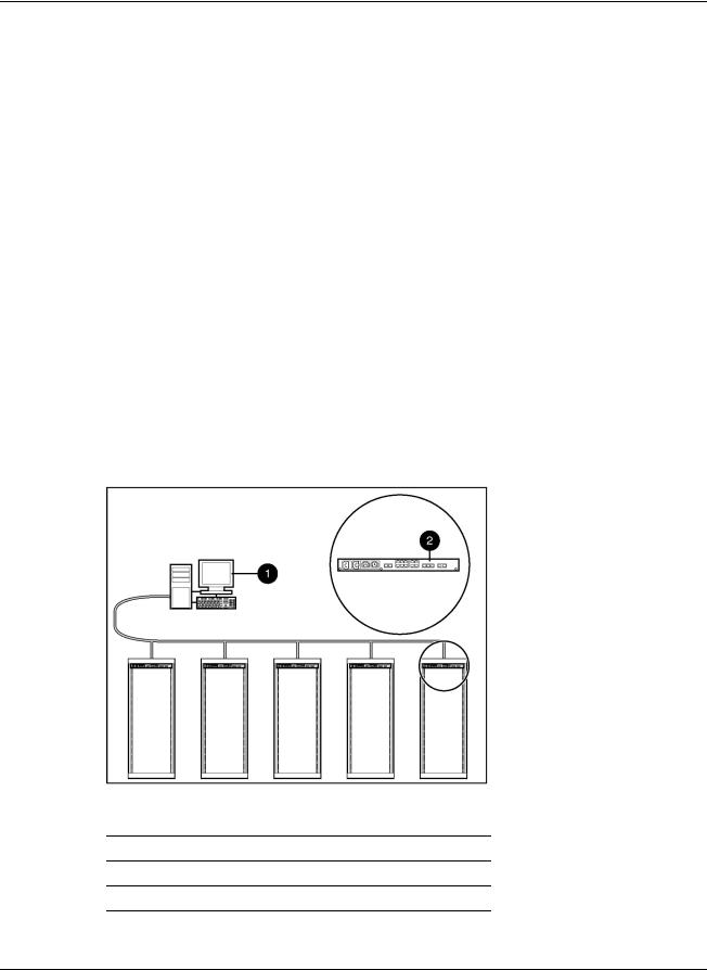
Configuration A
Figure 1-2 illustrates several CMCs connected directly to the network. The CMC is monitored by the Management Server, which is located elsewhere on the network.
Figure 1-2: Configuration A
Item Description
1HP Rack and Power Management Server*
2CMC
*A dedicated Management Server is not required.
1-8 |
HP Rack and Power Manager User Guide |
Overview
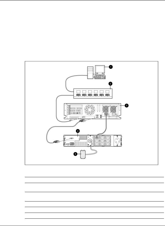
Configuration B
Figure 1-3 illustrates a UPS serially attached to a server that is plugged into a load segment of the UPS. The server is connected directly to the network. A Management Server is located elsewhere on the network. The server has an installed System Agent that receives commands, such as displaying a pop-up message or shutting down the operating system, from the Management Server. The server also has an installed Serial Relay Agent that is used for communication between the UPS and the Management Server.
NOTE: Installed agents must be associated with the correct server or UPS load segment in HP Rack and Power Manager. For information on associating agents, refer to “Attached Agents Screen” in Chapter 5.
Figure 1-3: Configuration B
Item Description
1HP Rack and Power Management Server*
2Additional servers power protected by a single UPS (each server requires installation of the System Agent)
3Power protected server that is serially attached to the UPS (requires installation of the System Agent and the Serial Relay Agent)
4UPS with a serial communication cable attached
5Utility power feed
*A dedicated Management Server is not required.
HP Rack and Power Manager User Guide |
1-9 |

Overview
Configuration C
Figure 1-4 illustrates a server that is plugged into a load segment of a UPS. Both the UPS and the server are directly connected to the network. The UPS is monitored by a Management Server that is located elsewhere on the network. The server has an installed System Agent that receives commands, such as displaying a pop-up message or shutting down the operating system, from the Management Server.
NOTE: Installed agents must be associated with the correct server or UPS load segment in HP Rack and Power Manager. For information on associating agents, refer to “Attached Agents Screen” in Chapter 5.
Figure 1-4: Configuration C
Item Description
1HP Rack and Power Management Server*
2Additional servers power protected by a single UPS (each server requires installation of the System Agent)
3Power protected server (requires installation of the System Agent)
4UPS with an HP SNMP Adapter Card installed
5Utility power feed
*A dedicated Management Server is not required.
1-10 |
HP Rack and Power Manager User Guide |

Overview
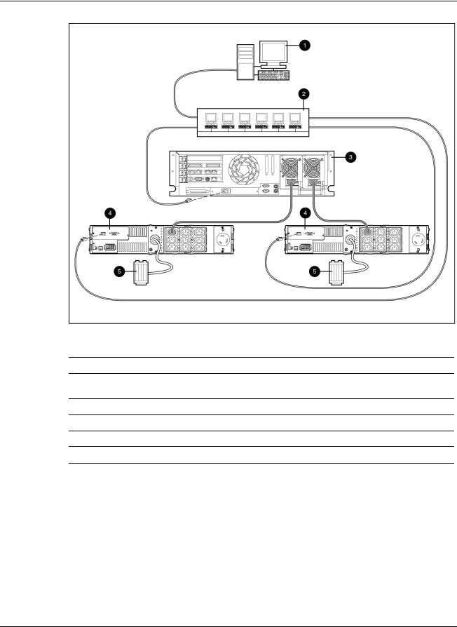
Configuration D
Figure 1-5 illustrates a redundant configuration in which servers with dual power supplies are protected by multiple UPSs. The servers are both serially attached to different UPSs. One server power supply is connected to a receptacle on the rear panel of each UPS. Each UPS is connected to a separate power feed. The UPSs are monitored by a Management Server located elsewhere on the network. Each server has an installed System Agent that receives commands, such as displaying a pop-up message or shutting down the operating system, from the Management Server. The servers also each have an installed Serial Relay Agent that is used for communication between the UPS and the Management Server.
IMPORTANT: When planning a redundant configuration, consider that in normal operating conditions, servers with multiple power supplies equally distribute the power load across each power feed. A server with two power supplies applies 50% of the load to each power feed. In the event that
one power feed fails, the second power feed must be able to handle 100% of the load. Ensure that each UPS in the redundant configuration can support the entire load in the event of a power failure.
Redundant UPS configurations should be tested thoroughly to ensure the load handling capabilities and power fail settings of each UPS before an actual power failure event.
HP Rack and Power Manager User Guide |
1-11 |
Overview
Figure 1-5: Configuration D
Item Description
1HP Rack and Power Management Server*
2Additional servers power protected by multiple UPSs (each server requires installation of the System Agent)
3Redundant power protected server that is serially attached to the UPS (requires installation of the System Agent and the Serial Relay Agent)
4Redundant power protected server that is serially attached to the UPS (requires installation of the System Agent and the Serial Relay Agent)
5UPS with a serial communication cable attached
6Utility power feed
*A dedicated Management Server is not required.
1-12 |
HP Rack and Power Manager User Guide |

Overview
Configuration E
Figure 1-6 illustrates a redundant configuration in which one server with dual power supplies is protected by multiple UPSs. One server power supply is connected to a receptacle on the rear panel of each UPS. Each UPS is connected to a separate power feed. The UPSs are monitored by a Management Server located elsewhere on the network. Each server has an installed System Agent that receives commands, such as displaying a pop-up message or shutting down the operating system, from the Management Server.
IMPORTANT: When planning a redundant configuration, consider that in normal operating conditions, servers with multiple power supplies equally distribute the power load across each power feed. A server with two power supplies applies 50% of the load to each power feed. In the event that
one power feed fails, the second power feed must be able to handle 100% of the load. Ensure that each UPS in the redundant configuration can support the entire load in the event of a power failure.
Redundant UPS configurations should be tested thoroughly to ensure the load handling capabilities and power fail settings of each UPS before an actual power failure event.
HP Rack and Power Manager User Guide |
1-13 |
Overview
Figure 1-6: Configuration E
Item Description
1HP Rack and Power Management Server*
2Additional servers power protected by multiple UPSs (each server requires installation of the System Agent)
3Redundant power protected server (requires installation of the System Agent)
4UPS with an HP SNMP Adapter Card installed
5Utility power feed
*A dedicated Management Server is not required.
1-14 |
HP Rack and Power Manager User Guide |

Overview
Configuration F
Figure 1-7 illustrates a redundant configuration in which servers with dual power supplies are protected by multiple UPSs. One server is serially attached to a UPS. The first server and a second UPS are connected directly to the network. One server power supply is connected to a receptacle on the rear panel of each UPS. Each UPS is connected to a separate power feed. The UPSs are monitored by a Management Server located elsewhere on the network.
IMPORTANT: When planning a redundant configuration, consider that in normal operating conditions, servers with multiple power supplies equally distribute the power load across each power feed. A server with two power supplies applies 50% of the load to each power feed. In the event that
one power feed fails, the second power feed must be able to handle 100% of the load. Ensure that each UPS in the redundant configuration can support the entire load in the event of a power failure.
Redundant UPS configurations should be tested thoroughly to ensure the load handling capabilities and power fail settings of each UPS before an actual power failure event.
HP Rack and Power Manager User Guide |
1-15 |

Overview
Figure 1-7: Configuration F
Item Description
1HP Rack and Power Management Server*
2Additional servers power protected by multiple UPSs (each server requires installation of the System Agent)
3Redundant power protected server (requires installation of the System Agent)
4Redundant power protected server that is serially attached to the UPS (requires installation of the System Agent and the Serial Relay Agent)
5UPS with an HP SNMP Adapter Card installed
6UPS with a serial communication cable attached
7Utility power feed
*A dedicated Management Server is not required.
1-16 |
HP Rack and Power Manager User Guide |

Overview
Configuration G
Figure 1-8 illustrates a server that is not connected to a UPS but is directly connected to the network. The server has an installed System Agent that receives commands, such as displaying a pop-up message or shutting down the operating system, from the Management Server.
NOTE: Installed agents must be associated with the correct server or UPS load segment in HP Rack and Power Manager. For information on associating agents, refer to “Attached Agents Screen” in Chapter 5.
Figure 1-8: Configuration G
Item Description
1HP Rack and Power Management Server*
2Additional non-power protected servers (each server requires installation of the System Agent)
3Non-power protected server (requires installation of the System Agent)
*A dedicated Management Server is not required.
HP Rack and Power Manager User Guide |
1-17 |

Overview
Power Protection for the Rack and Power Management Server
Power protection for the Management Server is essential. The Management Server is the central point of control of the Rack and Power Management environment. If the Management Server goes down, control of all managed devices is lost. Supported power protection configurations for the Management Server are detailed in Table 1-1.
Table 1-1: Management Server Power Protection Configurations
Number of UPSs |
UPS Connections |
Components Required on |
|
|
|
Management Server |
|
|
|
|
|
Single |
UPS serially attached to the |
• |
HP Rack and Power |
|
Management Server |
|
Manager |
|
|
• |
System Agent |
|
|
• |
Serial Relay Agent |
|
|
|
|
Single |
Network connected |
• |
HP Rack and Power |
|
|
|
Manager |
|
|
• |
System Agent |
|
|
|
|
Redundant |
Both UPSs network connected |
• |
HP Rack and Power |
|
|
|
Manager |
|
|
• |
System Agent |
|
|
|
|
Redundant |
Both UPSs serially attached* |
• |
HP Rack and Power |
|
|
|
Manager |
|
|
• |
System Agent |
|
|
• |
Serial Relay Agent |
|
|
|
|
Redundant |
One UPS serially attached, one UPS |
• |
HP Rack and Power |
|
network connected |
|
Manager |
|
|
• |
System Agent |
|
|
• |
Serial Relay Agent |
|
|
|
|
*If this configuration is used, the serial communications cable from the second UPS must be connected to a separate server.
1-18 |
HP Rack and Power Manager User Guide |

2
Installation
System Requirements
IMPORTANT: Verify that the system meets the system requirements before installing HP Rack and Power Manager.
Table 2-1: Management Server System Requirements
Hardware and |
Suggested Minimum Requirements |
Software |
|
|
|
Hardware |
500-MHz Intel® Pentium® computer |
|
|
Disk space |
100 MB |
|
|
System memory |
256 MB of RAM |
|
|
Operating system |
• Microsoft Windows NT 4.0 Server with Service Pack 6 |
|
• Microsoft Windows 2000 Server with Service Pack 4 |
|
• Microsoft Windows 2000 Advanced Server with Service Pack 4 |
|
• Microsoft Windows 2003 Standard Server |
|
• Microsoft Windows 2003 Enterprise Edition |
|
• Red Hat Linux 7.3 Server with Errata Kernel 2.4.20-181 |
|
• Red Hat Linux 8.0 Server with Errata Kernel 2.4.20-181 |
|
• Red Hat Enterprise Linux WS/ES/AS 2.1 with Errata Kernel 2.4.9-e.251 |
|
• UnitedLinux 1.0 with Errata Kernel sp2a1, 2 |
|
|
Server software |
• A supported operating system with a static IP address (recommended), |
|
TCP/IP installed and configured |
•SNMP services installed and active
•A mail application program with SMTP for e-mail notification of alerts
1Linux servers running the Management Server component require XWindows with a supported GUI and the compatible library compat-libstdc++.x.x.x.rpm, which is usually available from the operating system media.
2Conectiva Linux Enterprise Edition, SCO Linux 4.0, SUSE Linux Enterprise 8, and Turbolinux 8 are all powered by UnitedLinux 1.0.
HP Rack and Power Manager User Guide |
2-1 |

Installation
Table 2-2: System Agent System Requirements
Hardware and |
Suggested Minimum Requirements |
Software |
|
|
|
Hardware |
233-MHz Pentium computer |
|
|
Disk space |
10 MB free disk space |
|
|
System memory |
64 MB of RAM |
|
|
Operating system |
• Microsoft Windows NT 4.0 Server with Service Pack 6 |
|
• Microsoft Windows 2000 Server with Service Pack 4 |
|
• Microsoft Windows 2000 Advanced Server with Service Pack 4 |
|
• Microsoft Windows 2003 Standard Server |
|
• Microsoft Windows 2003 Enterprise Edition |
|
• Novell NetWare 5.1 with Support Pack 6 |
|
• Novell NetWare 6.0 with Support Pack 3 |
|
• Red Hat Linux 7.3 Server with Errata Kernel 2.4.20-181 |
|
• Red Hat Linux 8.0 Server with Errata Kernel 2.4.20-181 |
|
• Red Hat Enterprise Linux WS/ES/AS 2.1 with Errata Kernel 2.4.9-e.251 |
|
• UnitedLinux 1.0 with Errata Kernel sp2a1, 2 |
|
|
Network |
Static IP Address |
1Linux servers running the Management Server component require XWindows with a supported GUI and the compatible library compat-libstdc++.x.x.x.rpm, which is usually available from the operating system media.
2Conectiva Linux Enterprise Edition, SCO Linux 4.0, SUSE Linux Enterprise 8, and Turbolinux 8 are all powered by UnitedLinux 1.0.
2-2 |
HP Rack and Power Manager User Guide |

Installation
Table 2-3: Serial Relay Agent System Requirements
Hardware and |
Suggested Minimum Requirements |
Software |
|
|
|
Hardware |
233-MHz Pentium computer |
|
|
Disk space |
10 MB free disk space |
|
|
System memory |
64 MB of RAM |
|
|
Operating system |
• Microsoft Windows NT 4.0 Server with Service Pack 6 |
|
• Microsoft Windows 2000 Server with Service Pack 4 |
|
• Microsoft Windows 2000 Advanced Server with Service Pack 4 |
|
• Microsoft Windows 2003 Standard Server |
|
• Microsoft Windows 2003 Enterprise Edition |
|
• Novell NetWare 5.1 with Support Pack 6 |
|
• Novell NetWare 6.0 with Support Pack 3 |
|
• Red Hat Linux 7.3 Server with Errata Kernel 2.4.20-181 |
|
• Red Hat Linux 8.0 Server with Errata Kernel 2.4.20-181 |
|
• Red Hat Enterprise Linux WS/ES/AS 2.1 with Errata Kernel 2.4.9-e.251 |
|
• UnitedLinux 1.0 with Errata Kernel sp2a1, 2 |
1Linux servers running the Management Server component require XWindows with a supported GUI and the compatible library compat-libstdc++.x.x.x.rpm, which is usually available from the operating system media.
2Conectiva Linux Enterprise Edition, SCO Linux 4.0, SUSE Linux Enterprise 8, and Turbolinux 8 are all powered by UnitedLinux 1.0.
HP Rack and Power Manager User Guide |
2-3 |
 Loading...