


HP ProLiant ML370 Generation 4 Server
Maintenance and Service Guide
March 2006 (Eighth Edition)
Part Number 346895-008
© Copyright 2004, 2006 Hewlett-Packard Development Company, L.P.
The information contained herein is subject to change without notice. The only warranties for HP products and services are set forth in the express limited warranty statements accompanying such products and services. Nothing herein should be construed as constituting an additional warranty. HP shall not be liable for technical or editorial errors or omissions contained herein.
Microsoft, Windows, and Windows NT are US registered trademarks of Microsoft Corporation. Windows Server 2003 is a trademark of Microsoft Corporation.
Intel and Xeon are trademarks or registered trademarks of Intel Corporation or its subsidiaries in the United States and other countries.
Linux is a U.S. registered trademark of Linus Torvalds.
March 2006 (Eighth Edition)
Part Number 346895-008
Audience assumptions
This document is for the person who installs, administers, and troubleshoots servers and storage systems. HP assumes you are qualified in the servicing of computer equipment and trained in recognizing hazards in products with hazardous energy levels.

Contents |
|
Illustrated parts catalog ................................................................................................................. |
6 |
Customer self repair................................................................................................................................... |
6 |
Mechanical components............................................................................................................................. |
7 |
System components ................................................................................................................................... |
8 |
Removal and replacement procedures........................................................................................... |
13 |
Required tools......................................................................................................................................... |
13 |
Safety considerations............................................................................................................................... |
14 |
Preventing electrostatic discharge .................................................................................................... |
14 |
Symbols on equipment ................................................................................................................... |
14 |
Rack warnings .............................................................................................................................. |
15 |
Preparation procedures............................................................................................................................ |
15 |
Power down the server................................................................................................................... |
16 |
Extending the server from the rack ................................................................................................... |
16 |
Removing the server from the rack ................................................................................................... |
17 |
Feet ....................................................................................................................................................... |
17 |
Front bezel ............................................................................................................................................. |
19 |
Access panel .......................................................................................................................................... |
20 |
Rack bezel ............................................................................................................................................. |
20 |
Tower hood cover ................................................................................................................................... |
21 |
Rack rails ............................................................................................................................................... |
22 |
Power supply blank ................................................................................................................................. |
23 |
Hot-plug power supply ............................................................................................................................. |
23 |
Hard drive blank (SCSI) ........................................................................................................................... |
24 |
Hard drives (SCSI)................................................................................................................................... |
25 |
Hard drive cage (SCSI) ............................................................................................................................ |
25 |
Hard drive blank (SAS) ............................................................................................................................ |
26 |
Hard drives (SAS) ................................................................................................................................... |
27 |
Hard drive cage (SAS)............................................................................................................................. |
28 |
System fans ............................................................................................................................................ |
29 |
Redundant hot-plug fan cage .................................................................................................................... |
30 |
Expansion slot cover ................................................................................................................................ |
32 |
Slot release lever..................................................................................................................................... |
33 |
Expansion board..................................................................................................................................... |
33 |
Processor air baffle.................................................................................................................................. |
34 |
Center wall............................................................................................................................................. |
35 |
CD-ROM drive ........................................................................................................................................ |
36 |
Power button/LED assembly...................................................................................................................... |
37 |
Diskette drive .......................................................................................................................................... |
38 |
Processor assembly.................................................................................................................................. |
39 |
Processor power module (PPM) ................................................................................................................. |
42 |
DIMM.................................................................................................................................................... |
43 |
SCSI backplane ...................................................................................................................................... |
44 |
Duplex SCSI board.................................................................................................................................. |
45 |
VHDCI or HD68 SCSI cable option ........................................................................................................... |
46 |
Power supply backplane .......................................................................................................................... |
47 |
System board ......................................................................................................................................... |
48 |
Battery ................................................................................................................................................... |
49 |
Re-entering the server serial number and product ID..................................................................................... |
50 |
Server cabling ............................................................................................................................ |
51 |
Contents |
3 |
Cabling overview.................................................................................................................................... |
51 |
Hot-plug SCSI cabling.............................................................................................................................. |
51 |
Integrated simplex SCSI cabling ...................................................................................................... |
51 |
Integrated duplex SCSI cabling ....................................................................................................... |
52 |
Integrated SCSI cabling with optional internal two-bay hot-plug SCSI drive cage ................................... |
53 |
Array controller simplex SCSI cabling .............................................................................................. |
54 |
Array controller duplex SCSI cabling ............................................................................................... |
54 |
Array controller duplex SCSI cabling with optional internal two-bay hot-plug SCSI drive cage ................. |
55 |
SAS cabling ........................................................................................................................................... |
55 |
CD-ROM drive cabling............................................................................................................................. |
57 |
Diskette drive cabling .............................................................................................................................. |
57 |
External storage cabling........................................................................................................................... |
58 |
Storage device cabling guidelines ............................................................................................................. |
58 |
RILOE II cabling ...................................................................................................................................... |
58 |
Diagnostic tools .......................................................................................................................... |
60 |
Automatic Server Recovery ....................................................................................................................... |
60 |
HP Systems Insight Manager..................................................................................................................... |
60 |
Integrated Management Log ..................................................................................................................... |
60 |
Lights Out Manager technology ................................................................................................................ |
61 |
Option ROM Configuration for Arrays ....................................................................................................... |
61 |
ProLiant Essentials Rapid Deployment Pack ................................................................................................. |
61 |
HP ROM-Based Setup Utility ..................................................................................................................... |
62 |
ROMPaq utility........................................................................................................................................ |
62 |
System Online ROM flash component utility ................................................................................................ |
62 |
SmartStart software ................................................................................................................................. |
62 |
SmartStart Scripting Toolkit ............................................................................................................. |
63 |
HP Insight Diagnostics.................................................................................................................... |
63 |
Server component identification.................................................................................................... |
64 |
Front panel components ........................................................................................................................... |
64 |
Front panel LEDs and buttons .................................................................................................................... |
65 |
Rear panel components............................................................................................................................ |
66 |
Rear panel LEDs and buttons..................................................................................................................... |
66 |
System board components........................................................................................................................ |
68 |
System maintenance switch............................................................................................................. |
68 |
Power supply backplane LED .......................................................................................................... |
69 |
DIMM slots ................................................................................................................................... |
70 |
System board LEDs .................................................................................................................................. |
70 |
System LEDs and internal health LED combinations....................................................................................... |
71 |
Hot-plug SCSI hard drive LEDs .................................................................................................................. |
72 |
SATA or SAS hard drive LEDs ................................................................................................................... |
73 |
Identifying redundant hot-plug fans ............................................................................................................ |
73 |
Hot-plug fan LEDs .................................................................................................................................... |
74 |
Specifications............................................................................................................................. |
75 |
Server specifications ................................................................................................................................ |
75 |
Environmental specifications ..................................................................................................................... |
75 |
Hot-plug power supply calculations............................................................................................................ |
76 |
DDR2 SDRAM DIMM specifications ........................................................................................................... |
76 |
1.44-MB diskette drive specifications ......................................................................................................... |
76 |
CD-ROM drive specifications .................................................................................................................... |
77 |
Ultra320 SCSI hard drive specifications ..................................................................................................... |
78 |
SAS and SATA hard drive specifications .................................................................................................... |
78 |
Contents 4
Acronyms and abbreviations........................................................................................................ |
79 |
Index......................................................................................................................................... |
82 |
Contents 5

Illustrated parts catalog
In this section |
|
Customer self repair ................................................................................................................................. |
6 |
Mechanical components ........................................................................................................................... |
7 |
System components .................................................................................................................................. |
8 |
Customer self repair |
|
What is customer self repair? |
|
HP's customer self-repair program offers you the fastest service under either warranty or contract. It enables HP to ship replacement parts directly to you so that you can replace them. Using this program, you can replace parts at your own convenience.
A convenient, easy-to-use program:
•An HP support specialist will diagnose and assess whether a replacement part is required to address a system problem. The specialist will also determine whether you can replace the part.
•Replacement parts are express-shipped. Most in-stock parts are shipped the very same day you contact HP. You may be required to send the defective part back to HP, unless otherwise instructed.
•Available for most HP products currently under warranty or contract. For information on the warranty service, refer to the HP website (http://h18004.www1.hp.com/products/servers/platforms/warranty/index.html).
For more information about HP's customer self-repair program, contact your local service provider. For the North American program, refer to the HP website (http://www.hp.com/go/selfrepair).
Customer replaceable parts are identified in the following tables.
Illustrated parts catalog 6
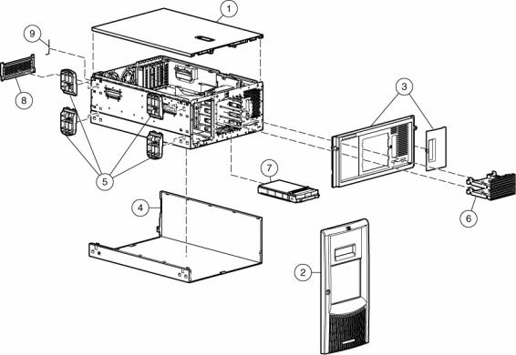
Mechanical components
Item |
Description |
Original |
Modified spare |
Customer self |
|
|
spare part |
part number |
repair (on |
|
|
number |
|
page 6) |
|
|
|
|
|
1 |
Access panel (top cover) |
359233-001 |
— |
Yes |
|
|
|
|
|
2 |
Front bezel (tower model only) |
359234-001 |
— |
Yes |
|
|
|
|
|
3 |
Rack bezel (rack model only) |
359235-001 |
— |
Yes |
|
|
|
|
|
4 |
Hood cover (tower model only) |
359236-001 |
— |
Yes |
|
|
|
|
|
5 |
Feet (tower model only) (part of kit |
— |
— |
Yes |
|
365962-001) |
|
|
|
|
|
|
|
|
6 |
Removable media blanks |
359715-001 |
— |
Yes |
|
|
|
|
|
7 |
Hard drive blank |
— |
— |
— |
|
|
|
|
|
|
a) SCSI |
122759-001 |
— |
Yes |
|
|
|
|
|
|
b) SAS* |
392613-001 |
— |
Yes |
|
|
|
|
|
8 |
Power supply blank |
359716-001 |
— |
Yes |
|
|
|
|
|
9 |
T-15 Torx screwdriver |
290557-001 |
— |
Yes |
|
|
|
|
|
*Not shown
Illustrated parts catalog 7

System components
Item |
Description |
Original spare part |
Modified |
Customer self |
|
|
|
number |
spare part |
repair (on |
|
|
|
|
number |
page 6) |
|
|
|
|
|
|
|
|
System components |
|
|
|
|
|
|
|
|
|
|
10 |
Power supply, 800 W |
347883-001‡ See |
406867-001 |
Yes |
|
|
|
requirement |
|
|
|
|
|
|
|
|
|
11 |
Fan, 92 mm |
231213-001 |
— |
Yes |
|
|
|
|
|
|
|
12 |
3.3-V lithium battery |
153099-001 |
— |
Yes |
|
|
|
|
|
|
|
13 |
Power button/switch with cable |
359714-001 |
— |
Yes |
|
|
|
|
|
|
|
14 |
Processor with heatsink |
— |
— |
— |
|
|
|
|
|
|
|
|
a) Intel® Xeon™ 3.0-GHz 1-MB L2 |
378006-001 |
— |
Yes |
|
|
cache* † |
|
|
|
|
|
|
|
|
|
|
|
b) Intel® Xeon™ 3.2-GHz 1-MB L2 |
374233-001 |
— |
Yes |
|
|
cache* † |
|
|
|
|
|
|
|
|
Illustrated parts catalog 8 |
|

Item |
Description |
Original spare part |
Modified |
Customer self |
|
|
number |
spare part |
repair (on |
|
|
|
number |
page 6) |
|
|
|
|
|
|
c) Intel® Xeon™ 3.4-GHz 1-MB L2 |
364757-001 |
— |
Yes |
|
cache † |
|
|
|
|
d) Intel® Xeon™ 3.6-GHz 1-MB L2 |
364758-001 |
— |
Yes |
|
cache* † |
|
|
|
|
|
|
|
|
|
e) Intel® Xeon™ 2.8-GHz 2-MB L2 |
399132-001 |
— |
Yes |
|
cache* † |
|
|
|
|
|
|
|
|
|
f) Intel® Xeon™ 3.0-GHz 2-MB L2 |
379427-001 |
— |
Yes |
|
cache* † |
|
|
|
|
g) Intel® Xeon™ 3.2-GHz 2-MB L2 |
379428-001 |
— |
Yes |
|
cache* † |
|
|
|
|
|
|
|
|
|
h) Intel® Xeon™ 3.4-GHz 2-MB L2 |
379429-001 |
— |
Yes |
|
cache* † |
|
|
|
|
|
|
|
|
|
i) Intel® Xeon™ 3.6-GHz 2-MB L2 |
379430-001 |
— |
Yes |
|
cache* † |
|
|
|
|
j) Intel® Xeon™ 3.8-GHz 2-MB L2 |
399133-001 |
— |
Yes |
|
cache* † |
|
|
|
|
|
|
|
|
|
k) Intel® Xeon™ dual-core, 1066-Mhz |
403934-001 |
— |
Yes |
|
FSB, 4-MB cache for use with dual-core |
|
|
|
|
system I/O board 012974-001 only |
|
|
|
|
Boards |
|
|
|
|
|
|
|
|
15 |
a) System board with processor cage |
347882-001 |
— |
Yes |
|
(for use with Intel® Xeon™ single-core |
|
|
|
|
processors) |
|
|
|
|
b) System board, dual-core processor |
408300-001‡ See |
408300-001 |
Yes |
|
support, with processor cage & battery |
requirement |
|
|
|
(for use with Intel® Xeon™ dual-core |
|
|
|
|
processors) |
|
|
|
16 |
PPM |
347884-001 |
— |
Yes |
|
|
|
|
|
17 |
Power supply backplane |
347886-001‡ See |
412735-001 |
Yes |
|
|
requirement |
|
|
|
|
|
|
|
18 |
Drive backplane |
— |
— |
— |
|
|
|
|
|
|
a) SCSI backplane Simplex with 6 x 1- |
359719-001 |
— |
Yes |
|
in drive cage |
|
|
|
|
|
|
|
|
|
b) SCSI backplane Duplex board with |
371722-001 |
— |
Yes |
|
drive cage* |
|
|
|
|
|
|
|
|
|
c) SAS backplane Duplex board with |
392607-001‡ See |
412736-001 |
Yes |
|
drive cage* |
requirement |
|
|
|
Mass storage devices |
|
|
|
|
|
|
|
|
19 |
Diskette drive, 3-mode, 1.44 MB |
233409-001‡ See |
399397-001 |
Yes |
|
|
requirement |
|
|
|
|
|
|
|
20 |
CD-ROM drive, IDE, 48x |
288894-001‡ See |
397931-001 |
Yes |
|
|
requirement |
|
|
|
Miscellaneous |
|
|
|
|
|
|
|
|
21 |
Plastics kit |
365962-001 |
— |
— |
|
|
|
|
|
|
a) Foot (refer to item number 5)* |
— |
— |
Yes |
|
|
|
|
|
Illustrated parts catalog 9

Item |
Description |
Original spare part |
Modified |
Customer self |
|
|
number |
spare part |
repair (on |
|
|
|
number |
page 6) |
|
|
|
|
|
|
b) Receptacle, door snap, stone* |
— |
— |
Yes |
|
|
|
|
|
|
c) Retainer, card guide, PCI |
— |
— |
Yes |
|
|
|
|
|
|
d) Fastener, 0.15-in plastic standoff* |
— |
— |
Yes |
|
|
|
|
|
|
e) Fastener, 0.202-in plastic standoff* |
— |
— |
Yes |
|
|
|
|
|
|
f) Clip, cable, adhesive, 1.77 in* |
— |
— |
Yes |
|
|
|
|
|
|
g) Clip, retainer, 0.125-in diameter* |
— |
— |
Yes |
|
|
|
|
|
|
h) Assembly, PCI latch and base |
— |
— |
Yes |
|
|
|
|
|
|
i) Cable clip* |
— |
— |
Yes |
|
|
|
|
|
|
j) Standoff bumper* |
— |
— |
Yes |
|
|
|
|
|
22 |
Hardware kit |
365963-001 |
— |
— |
|
|
|
|
|
|
a) Bracket, rear, removable |
— |
— |
Yes |
|
|
|
|
|
|
b) Bracket, diskette tray* |
— |
— |
Yes |
|
|
|
|
|
|
c) Bracket, diskette retainer* |
— |
— |
Yes |
|
|
|
|
|
|
d) Cover, slot, PCI expansion* |
— |
— |
Yes |
|
|
|
|
|
|
e) Bracket, blank, option board, PCI |
— |
— |
Yes |
|
latch* |
|
|
|
|
|
|
|
|
|
f) 2-56 pan head screw* |
— |
— |
Yes |
|
|
|
|
|
|
g) Hi-top screw* |
— |
— |
Yes |
|
|
|
|
|
23 |
Wall, center |
359238-001 |
— |
Yes |
|
|
|
|
|
24 |
Rack-mounting kit* |
359239-001 |
— |
Yes |
|
|
|
|
|
25 |
Cable management arm* |
367831-001 |
— |
Yes |
|
|
|
|
|
26 |
Country kit* |
359712-001 |
— |
Yes |
|
|
|
|
|
27 |
Return kit |
— |
— |
— |
|
|
|
|
|
|
a) Tower*, packing box and cushions |
359713-001 |
— |
Yes |
|
|
|
|
|
|
b) Rack*, packing box and cushions |
371561-001 |
— |
Yes |
|
|
|
|
|
28 |
Processor air baffle |
359240-001 |
— |
Yes |
|
|
|
|
|
|
Cables |
|
|
|
|
|
|
|
|
29 |
Miscellaneous data cable kit* |
365964-001 |
— |
— |
|
|
|
|
|
|
a) IDE hard drive/CD-ROM drive data |
— |
— |
Yes |
|
cable* |
|
|
|
|
b) Diskette drive cable* |
— |
— |
Yes |
|
|
|
|
|
|
c) Point-to-point SCSI cable* |
— |
— |
Yes |
|
|
|
|
|
|
d) USB cable assembly* |
— |
— |
Yes |
|
|
|
|
|
30 |
Miscellaneous power cable kit (SCSI)* |
365967-001 |
— |
— |
|
|
|
|
|
|
a) Diskette and CD-ROM drive power |
— |
— |
Yes |
|
cable (SCSI)* |
|
|
|
|
|
|
|
|
|
b) Power supply cable, 24 pin* |
— |
— |
Yes |
|
|
|
|
|
Illustrated parts catalog 10
Item |
Description |
Original spare part |
Modified |
Customer self |
|
|
number |
spare part |
repair (on |
|
|
|
number |
page 6) |
|
|
|
|
|
|
c) Fan cage cable* |
— |
— |
Yes |
|
|
|
|
|
31 |
Miscellaneous power cable kit (SAS)* |
392608-001 |
— |
— |
|
|
|
|
|
|
a) Diskette and CD-ROM drive power |
— |
— |
Yes |
|
cable (SAS)* |
|
|
|
|
|
|
|
|
32 |
SAS option cable* |
389952-001 |
— |
Yes |
|
|
|
|
|
|
Memory |
|
|
|
|
|
|
|
|
33 |
a) 512-MB PC2-3200R DIMM |
359241-001‡ See |
413384-001 |
Yes |
|
|
requirement |
|
|
|
|
|
|
|
|
b) 1-GB PC2-3200R DIMM* |
359242-001‡ See |
413385-001 |
Yes |
|
|
requirement |
|
|
|
|
|
|
|
|
c) 2-GB PC2-3200R DIMM* |
359243-001‡ See |
413386-001 |
Yes |
|
|
requirement |
|
|
|
d) 4-GB PC2-3200R DIMM |
379984-001‡ See |
413388-001 |
Yes |
|
|
requirement |
|
|
|
|
|
|
|
|
Options |
|
|
|
|
|
|
|
|
34 |
Rear fan cage |
230984-001 |
— |
Yes |
|
|
|
|
|
35 |
Two-bay, hot-plug SCSI hard drive |
253761-001 |
— |
Yes |
|
cage* |
|
|
|
36 |
Keyboard* |
311059-001‡ See |
382925-001 |
Yes |
|
|
requirement |
|
|
|
|
|
|
|
37 |
Mouse* |
311060-001‡ See |
390937-001 |
Yes |
|
|
requirement |
|
|
|
|
|
|
|
38 |
AC power cord* |
187335-001 |
— |
Yes |
|
|
|
|
|
39 |
SCSI Ultra320 universal hot-plug hard |
— |
— |
— |
|
drive* |
|
|
|
|
a) 72.8-GB, 10,000 rpm |
289042-001‡ See |
404709-001 |
Yes |
|
|
requirement |
|
|
|
|
|
|
|
|
b) 146.8-GB, 10,000 rpm |
289044-001‡ See |
404708-001 |
Yes |
|
|
requirement |
|
|
|
|
|
|
|
|
c) 300-GB, 10,000 rpm |
351126-001‡ See |
404701-001 |
Yes |
|
|
requirement |
|
|
|
e) 36.4-GB, 15,000 rpm |
289241001‡ See |
404714-001 |
Yes |
|
|
requirement |
|
|
|
|
|
|
|
|
f) 72.8-GB, 15,000 rpm |
289243-001‡ See |
404713-001 |
Yes |
|
|
requirement |
|
|
|
|
|
|
|
|
g) 146-GB, 15,000 rpm |
347779-001‡ See |
404712-001 |
Yes |
|
|
requirement |
|
|
40 |
SAS SFF hard drive* |
— |
— |
— |
|
|
|
|
|
|
a) 36-GB, 10,000 rpm |
376596-001 |
— |
Yes |
|
|
|
|
|
|
b) 72-GB, 10,000 rpm |
376597-001 |
— |
Yes |
|
|
|
|
|
|
c) 60-GB, 5,000 rpm SFF SATA |
382264-001 |
— |
Yes |
|
|
|
|
|
41 |
HP Smart Array P600 Controller |
370855-001 |
— |
Yes |
|
|
|
|
|
Illustrated parts catalog 11
* Not shown
†Do not mix single-core and dual-core processors, or processors with different cache sizes or speeds.
‡REQUIREMENT:
For Customers in the EU only.
The use of the Original Spare part is regulated by RoHS legislation§.
If your unit contains a part that is labelled with the Modified Spare number, the Modified Spare must be ordered as the replacement part in the EU.
If your unit contains a part that is labelled with the Original Spare number, please order the Original Spare as the replacement part in the EU. In this case either the Original Spare or the Modified Spare may be shipped which will not affect performance or functionality of the unit.
§Directive 2002/95/EC restricts the use of lead, mercury, cadmium, hexavalent chromium, PBBs and PBDEs in electronic products.
Illustrated parts catalog 12

Removal and replacement procedures
In this section |
|
Required tools........................................................................................................................................ |
13 |
Safety considerations.............................................................................................................................. |
14 |
Preparation procedures........................................................................................................................... |
15 |
Feet ...................................................................................................................................................... |
17 |
Front bezel ............................................................................................................................................ |
19 |
Access panel ......................................................................................................................................... |
20 |
Rack bezel ............................................................................................................................................ |
20 |
Tower hood cover .................................................................................................................................. |
21 |
Rack rails .............................................................................................................................................. |
22 |
Power supply blank ................................................................................................................................ |
23 |
Hot-plug power supply ............................................................................................................................ |
23 |
Hard drive blank (SCSI) .......................................................................................................................... |
24 |
Hard drives (SCSI).................................................................................................................................. |
25 |
Hard drive cage (SCSI)........................................................................................................................... |
25 |
Hard drive blank (SAS) ........................................................................................................................... |
26 |
Hard drives (SAS) .................................................................................................................................. |
27 |
Hard drive cage (SAS)............................................................................................................................ |
28 |
System fans ........................................................................................................................................... |
29 |
Redundant hot-plug fan cage ................................................................................................................... |
30 |
Expansion slot cover ............................................................................................................................... |
32 |
Slot release lever.................................................................................................................................... |
33 |
Expansion board.................................................................................................................................... |
33 |
Processor air baffle................................................................................................................................. |
34 |
Center wall............................................................................................................................................ |
35 |
CD-ROM drive ....................................................................................................................................... |
36 |
Power button/LED assembly .................................................................................................................... |
37 |
Diskette drive ......................................................................................................................................... |
38 |
Processor assembly................................................................................................................................. |
39 |
Processor power module (PPM) ................................................................................................................ |
42 |
DIMM ................................................................................................................................................... |
43 |
SCSI backplane ..................................................................................................................................... |
44 |
Duplex SCSI board................................................................................................................................. |
45 |
VHDCI or HD68 SCSI cable option .......................................................................................................... |
46 |
Power supply backplane ......................................................................................................................... |
47 |
System board................................................................................................................... |
...................... 48 |
Battery .................................................................................................................................................. |
49 |
Re-entering the server serial number and product ID ................................................................................... |
50 |
Required tools |
|
You need the following items for some procedures: |
|
|
Removal and replacement procedures 13 |

•T-15 Torx screwdriver (included with the server)
•Diagnostics Utility (included on the SmartStart CD-ROM)
Safety considerations
Before performing service procedures, review all the safety information.
Preventing electrostatic discharge
To prevent damaging the system, be aware of the precautions you need to follow when setting up the system or handling parts. A discharge of static electricity from a finger or other conductor may damage system boards or other static-sensitive devices. This type of damage may reduce the life expectancy of the device.
To prevent electrostatic damage:
•Avoid hand contact by transporting and storing products in static-safe containers.
•Keep electrostatic-sensitive parts in their containers until they arrive at static-free workstations.
•Place parts on a grounded surface before removing them from their containers.
•Avoid touching pins, leads, or circuitry.
•Always be properly grounded when touching a static-sensitive component or assembly.
Symbols on equipment
The following symbols may be placed on equipment to indicate the presence of potentially hazardous conditions.
This symbol indicates the presence of hazardous energy circuits or electric shock hazards. Refer all servicing to qualified personnel.
WARNING: To reduce the risk of injury from electric shock hazards, do not open this enclosure. Refer all maintenance, upgrades, and servicing to qualified personnel.
This symbol indicates the presence of electric shock hazards. The area contains no user or field serviceable parts. Do not open for any reason.
WARNING: To reduce the risk of injury from electric shock hazards, do not open this enclosure.
This symbol on an RJ-45 receptacle indicates a network interface connection.
WARNING: To reduce the risk of electric shock, fire, or damage to the equipment, do not plug telephone or telecommunications connectors into this receptacle.
This symbol indicates the presence of a hot surface or hot component. If this surface is contacted, the potential for injury exists.
WARNING: To reduce the risk of injury from a hot component, allow the surface to cool before touching.
Removal and replacement procedures 14

25-41 kg
55-90 lbs
Rack warnings
This symbol indicates that the component exceeds the recommended weight for one individual to handle safely.
WARNING: To reduce the risk of personal injury or damage to the equipment, observe local occupational health and safety requirements and guidelines for manual material handling.
These symbols, on power supplies or systems, indicate that the equipment is supplied by multiple sources of power.
WARNING: To reduce the risk of injury from electric shock, remove all power cords to completely disconnect power from the system.
WARNING: To reduce the risk of personal injury or damage to the equipment, be sure that:
•The leveling jacks are extended to the floor.
•The full weight of the rack rests on the leveling jacks.
•The stabilizing feet are attached to the rack if it is a single-rack installation.
•The racks are coupled together in multiple-rack installations.
•Only one component is extended at a time. A rack may become unstable if more than one component is extended for any reason.
WARNING: To reduce the risk of personal injury or equipment damage when unloading a rack:
•At least two people are needed to safely unload the rack from the pallet. An empty 42U rack can weigh as much as 115 kg (253 lb), can stand more than 2.1 m (7 ft) tall, and may become unstable when being moved on its casters.
•Never stand in front of the rack when it is rolling down the ramp from the pallet. Always handle the rack from both sides.
WARNING: To reduce the risk of personal injury or damage to the equipment, adequately stabilize the rack before extending a component outside the rack. Extend only one component at a time. A rack may become unstable if more than one component is extended.
WARNING: When installing a server in a telco rack, be sure that the rack frame is adequately secured to the top and bottom of the building structure.
Preparation procedures
To access some components and perform certain service procedures, you must perform one or more of the following procedures:
•Extend the server from the rack ("Extending the server from the rack" on page 16).
If you are performing service procedures in an HP, Compaq branded, telco, or third-party rack cabinet, you can use the locking feature of the rack rails to support the server and gain access to internal components.
For more information about telco rack solutions, refer to the RackSolutions.com website (http://www.racksolutions.com/hp).
•Power down the server (on page 16).
Removal and replacement procedures 15

If you must remove a server from a rack or a non-hot-plug component from a server, power down the server.
•Remove the server from the rack ("Removing the server from the rack" on page 17).
If the rack environment, cabling configuration, or the server location in the rack creates awkward conditions, remove the server from the rack.
Power down the server
WARNING: To reduce the risk of personal injury, electric shock, or damage to the equipment, remove the power cord to remove power from the server. The front panel Power On/Standby button does not completely shut off system power. Portions of the power supply and some internal circuitry remain active until AC power is removed.
IMPORTANT: If installing a hot-plug device, it is not necessary to power down the server.
1.Shut down the OS as directed by the OS documentation.
2.Press the Power On/Standby button to place the server in standby mode. When the server enters standby power mode, the system power LED changes to amber.
3.Disconnect the power cords.
The system is now without power.
Extending the server from the rack
1.Loosen the thumbscrews that secure the server faceplate to the front of the rack.
IMPORTANT: If the server is installed in a telco rack, remove the server from the rack to access internal components.
2.Extend the server on the rack rails until the server rail-release latches engage.
WARNING: To reduce the risk of personal injury or equipment damage, be sure that the rack is adequately stabilized before extending a component from the rack.
WARNING: To reduce the risk of personal injury, be careful when pressing the server rail-release latches and sliding the server into the rack. The sliding rails could pinch your fingers.
3.After performing the installation or maintenance procedure, slide the server back into the rack:
Removal and replacement procedures 16
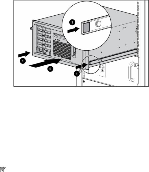
a. Press the server rail-release latches and slide the server fully into rack.
b. Secure the server by tightening the thumbscrews.
Removing the server from the rack
To remove the server from an HP, telco, or third-party rack:
1.Power down the server (on page 16).
2.Loosen the front panel thumbscrews that secure the server faceplate to the front of the rack.
3.Disconnect the cabling and remove the server from the rack. Reverse the server installation steps in the documentation that ships with the rack-mounting option.
4.Place the server on a sturdy, level surface.
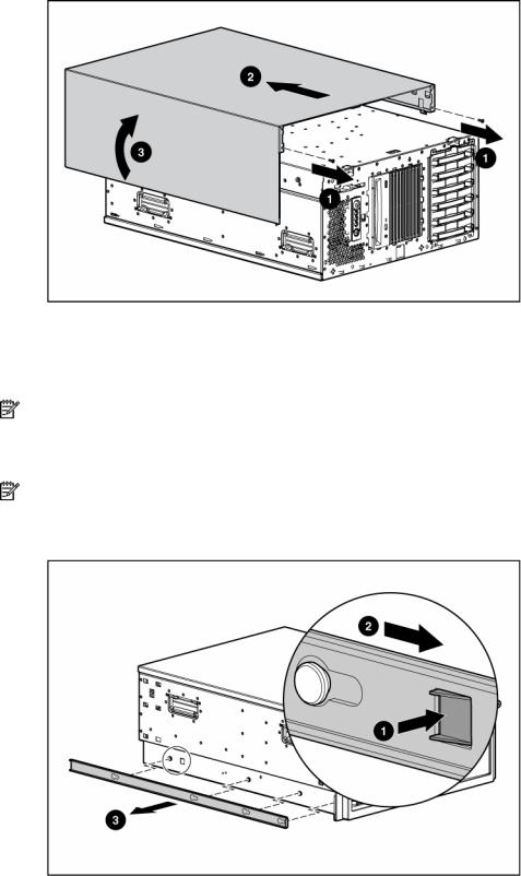
Feet
NOTE: This procedure applies to tower servers only.
To remove the component:
1.Place the server on its side.
Removal and replacement procedures 17

2.Remove the feet.
To replace the component, slide it back onto the locking slot. Be sure that the foot snaps securely into the holder. Repeat with the remaining feet, as necessary.
Removal and replacement procedures 18
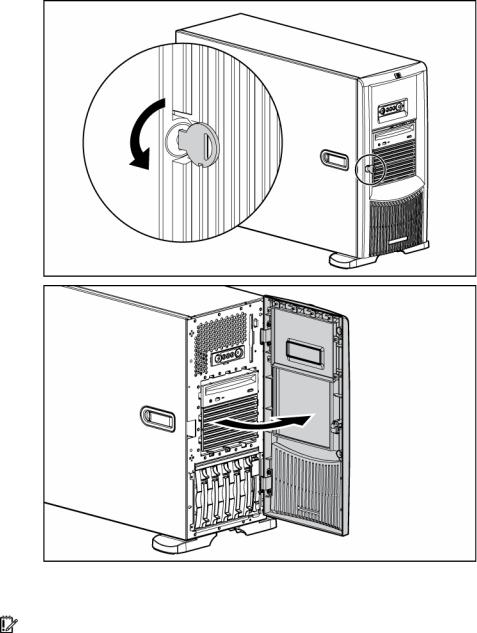
Front bezel
Tower servers have a removable front bezel that must be unlocked and opened before accessing the hard drive cage, diskette drive, and before removing the access panel.
To unlock the front bezel, use the key provided with the server to unlock the bezel with a counterclockwise turn.
To remove the component:
1.Unlock and open the front bezel ("Front bezel" on page 19) (tower servers only).
IMPORTANT: You must unlock the front bezel before removing the access panel.
Removal and replacement procedures 19
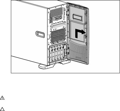
2.Lift up the front bezel and remove it from the chassis.
To replace the component, reverse the removal procedure.
Access panel
WARNING: To reduce the risk of personal injury from hot surfaces, allow the drives and the internal system components to cool before touching them.
CAUTION: Do not operate the server for long periods with the access panel open or removed. Operating the server in this manner results in improper airflow and improper cooling that can lead to thermal damage.
1.Power down the server (on page 16).
2.Extend or remove the server from the rack ("Extending the server from the rack" on page 16).
3.Open the front bezel ("Front bezel" on page 19).
4.Using a Torx T-15 screwdriver, unlock the access panel locking latch.
5.Lift up on the hood latch handle and remove the access panel.
After installing hardware options, replace the access panel. Be sure that the panel is securely locked into place before powering up the server.
Rack bezel
To remove the component:
1.Remove the access panel ("Access panel" on page 20).
2.Extend or remove the server from the rack ("Extending the server from the rack" on page 16).
Removal and replacement procedures 20
3.Loosen the two thumbscrews that secure the rack bezel to the chassis.
4.Remove the rack bezel.
To replace the component, reverse the removal procedure.
Tower hood cover
To remove the component:
1.Unlock and open the front bezel ("Front bezel" on page 19) (tower servers only).
2.Remove the rack bezel (rack servers only) ("Rack bezel" on page 20).
3.Use the Torx T-15 tool to remove the two front panel screws.
Removal and replacement procedures 21
4.Remove the tower hood cover.
To replace the component, reverse the removal procedure.
Rack rails
NOTE: This procedure applies to rack servers only.
To remove the component:
1.Use the Torx T-15 screwdriver to push in the release key.
NOTE: The T-15 Torx screwdriver is clipped to the rear panel of the server.
2.Press the rail against the side of the chassis and slide it to the front of the server to release the rails.
3.Align the four keyholes above the four spools on the side of the chassis and remove the rail.
4. Repeat steps 1 through 3 to remove the other rail.
To replace the component, reverse the removal procedure.
Removal and replacement procedures 22
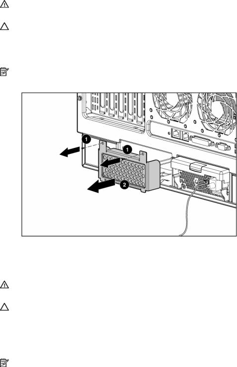
Power supply blank
WARNING: To reduce the risk of electric shock, do not disassemble the power supply or attempt to repair it. Replace it only with the specified spare part.
CAUTION: Do not attempt to remove and replace a power supply as a hot-plug procedure unless both bays are populated with power supplies.
To remove the component:
1.Remove the two screws with the T-15 Torx screwdriver.
NOTE: The T-15 Torx screwdriver is clipped to the rear panel of the server.
2.Remove the power supply blank.
To replace the component, reverse the removal procedure.
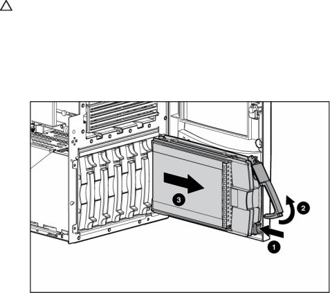
Hot-plug power supply
WARNING: To reduce the risk of electric shock, do not disassemble the power supply or attempt to repair it. Replace it only with the specified spare part.
CAUTION: Do not attempt to remove and replace a power supply as a hot-plug procedure unless both bays are populated with power supplies.
To remove the component:
1.Remove the power cord from the unit to be removed.
2.Use the Torx T-15 screwdriver to remove the shipping screw securing the handle.
NOTE: The T-15 Torx screwdriver is clipped to the rear panel of the server.
Removal and replacement procedures 23

3.Remove the power supply.
CAUTION: To prevent improper cooling and thermal damage, do not operate the server unless all bays are populated with either a component or a blank.
To replace the component, reverse the removal procedure.
Hard drive blank (SCSI)
CAUTION: To prevent improper cooling and thermal damage, do not operate the server unless all bays are populated with either a component or a blank.
To remove the component:
1.Unlock and open the front bezel ("Front bezel" on page 19) (tower servers only).
2.Remove the blank.
To replace the component, reverse the removal procedure.
Removal and replacement procedures 24
Hard drives (SCSI)
CAUTION: To prevent improper cooling and thermal damage, do not operate the server unless all bays are populated with either a component or a blank.
1.Unlock and open the front bezel ("Front bezel" on page 19) (tower servers only).
2.Determine the status of the hard drive from the hot-plug hard drive LEDs ("Hot-plug SCSI hard drive LEDs" on page 72, "SATA or SAS hard drive LEDs" on page 73).
3.Back up all server data on the hard drive.
4.Remove the hard drive.
To replace the component, reverse the removal procedure.
Hard drive cage (SCSI)
1.Power down the server (on page 16).
2.Unlock and open the front bezel ("Front bezel" on page 19) (tower servers only).
3.Remove the rack bezel (rack servers only) ("Rack bezel" on page 20).
4.Extend or remove the server from the rack ("Extending the server from the rack" on page 16).
5.Remove the access panel ("Access panel" on page 20).
6.Remove all hard drive blanks ("Hard drive blank (SCSI)" on page 24).
7.Remove all hot-plug SCSI hard drives ("Hard drives (SCSI)" on page 25).
8.If using the duplex SCSI board option, remove the duplex SCSI board (on page 45).
9.Disconnect the point-to-point SCSI cable from the SCSI hard drive backplane.
Removal and replacement procedures 25

10. Disconnect the power cable from the SCSI hard drive backplane.
11.Remove the four (4) screws that secure the hard drive cage into the chassis.
12.Remove the hard drive cage.
To replace the component, reverse the removal procedure.
CAUTION: When routing cables, always be sure that the cables are not in a position where they can be pinched or crimped.
Hard drive blank (SAS)
CAUTION: To prevent improper cooling and thermal damage, do not operate the server unless all bays are populated with either a component or a blank.
To remove the component:
1.Unlock and open the front bezel ("Front bezel" on page 19) (tower servers only).
Removal and replacement procedures 26
 Loading...