


HP ProLiant BL25p Server Blade
Maintenance and Service Guide
December 2005 (Fourth Edition)
Part Number 377851-004A
© Copyright 2005 Hewlett-Packard Development Company, L.P.
The information contained herein is subject to change without notice. The only warranties for HP products and services are set forth in the express warranty statements accompanying such products and services. Nothing herein should be construed as constituting an additional warranty. HP shall not be liable for technical or editorial errors or omissions contained herein.
Microsoft and Windows are U.S. registered trademarks of Microsoft Corporation.
Linux is a U.S. registered trademark of Linus Torvalds.
AMD Opteron is a trademark of Advanced Micro Devices, Inc.
December 2005 (Fourth Edition)
Part Number 377851-004A
Audience assumptions
This guide is for an experienced service technician. HP assumes you are qualified in the servicing of computer equipment and trained in recognizing hazards in products with hazardous energy levels and are familiar with weight and stability precautions for rack installations.

Contents |
|
Illustrated parts catalog ................................................................................................................. |
5 |
Customer self repair................................................................................................................................... |
5 |
Server blade components ........................................................................................................................... |
6 |
Removal and replacement procedures............................................................................................. |
8 |
Safety considerations................................................................................................................................. |
8 |
Preventing electrostatic discharge ...................................................................................................... |
8 |
Server blade warnings and cautions .................................................................................................. |
9 |
Rack warnings and cautions ............................................................................................................. |
9 |
Symbols on equipment ................................................................................................................... |
10 |
Server blade preparation ......................................................................................................................... |
11 |
Access panel .......................................................................................................................................... |
12 |
Hard drives ............................................................................................................................................ |
12 |
DIMMs................................................................................................................................................... |
13 |
Processor ............................................................................................................................................... |
14 |
HP Smart Array 6i Controller .................................................................................................................... |
17 |
HP Smart Array 6i battery-backed write cache enabler (optional) .................................................................. |
18 |
Air baffle ............................................................................................................................................... |
18 |
Fan assembly.......................................................................................................................................... |
19 |
Fibre Channel mezzanine (optional) .......................................................................................................... |
20 |
Standard NIC mezzanine card ................................................................................................................. |
21 |
SCSI backplane ...................................................................................................................................... |
22 |
Power converter module ........................................................................................................................... |
23 |
DC filter module...................................................................................................................................... |
23 |
Power button/LED board .......................................................................................................................... |
24 |
System board battery............................................................................................................................... |
25 |
System board ......................................................................................................................................... |
26 |
Server blade bay blank............................................................................................................................ |
28 |
Diagnostic tools .......................................................................................................................... |
29 |
HP Insight Diagnostics.............................................................................................................................. |
29 |
Survey Utility .......................................................................................................................................... |
29 |
Integrated Management Log ..................................................................................................................... |
29 |
Server component identification.................................................................................................... |
31 |
Front panel components ........................................................................................................................... |
31 |
Front panel LEDs ..................................................................................................................................... |
32 |
Rear panel components............................................................................................................................ |
33 |
Internal components................................................................................................................................. |
34 |
System maintenance switch....................................................................................................................... |
35 |
System maintenance switch procedures ...................................................................................................... |
35 |
Clearing the system configuration .................................................................................................... |
35 |
Accessing the redundant ROM ........................................................................................................ |
36 |
Local I/O cable ...................................................................................................................................... |
36 |
Hot-plug SCSI hard drive LEDs .................................................................................................................. |
37 |
Hot-plug SCSI hard drive LED combinations ................................................................................................ |
37 |
Specifications............................................................................................................................. |
39 |
Environmental specifications ..................................................................................................................... |
39 |
Server specifications ................................................................................................................................ |
39 |
Acronyms and abbreviations........................................................................................................ |
40 |
Contents |
3 |
Index......................................................................................................................................... |
42 |
Contents 4

Illustrated parts catalog
In this section |
|
Customer self repair ................................................................................................................................. |
5 |
Server blade components .......................................................................................................................... |
6 |
Customer self repair |
|
What is customer self repair? |
|
HP's customer self-repair program offers you the fastest service under either warranty or contract. It enables HP to ship replacement parts directly to you so that you can replace them. Using this program, you can replace parts at your own convenience.
A convenient, easy-to-use program:
•An HP support specialist will diagnose and assess whether a replacement part is required to address a system problem. The specialist will also determine whether you can replace the part.
•Replacement parts are express-shipped. Most in-stock parts are shipped the very same day you contact HP. You may be required to send the defective part back to HP, unless otherwise instructed.
•Available for most HP products currently under warranty or contract. For information on the warranty service, refer to the HP website (http://h18004.www1.hp.com/products/servers/platforms/warranty/index.html).
For more information about HP's customer self-repair program, contact your local service provider. For the North American program, refer to the HP website (http://www.hp.com/go/selfrepair).
Customer replaceable parts are identified in the following tables.
Illustrated parts catalog 5

Server blade components
Item |
Description |
Spare part |
Customer |
|
|
number |
replaceable? |
|
|
|
|
|
Mechanical components |
|
|
|
|
|
|
1 |
Access panel |
371709-001 |
Yes |
|
|
|
|
2 |
Hard drive blank |
122759-001 |
Yes |
|
|
|
|
|
Boards |
|
|
|
|
|
|
3 |
Power button/LED board kit with LED cable (cable not |
371706-001 |
Yes |
|
shown *) |
|
|
|
|
|
|
4 |
SCSI backplane with cables (cables not shown *) |
371701-001 |
Yes |
|
|
|
|
5 |
System board |
381811-001 |
Yes |
|
|
|
|
6 |
Standard NIC mezzanine card |
381816-001 |
Yes |
|
|
|
|
7 |
HP Smart Array 6i Controller |
371702-001 |
Yes |
|
|
|
|
|
System components |
|
|
|
|
|
|
8 |
Processor heatsink |
381812-001 |
Yes |
|
|
|
|
9 |
Processor |
|
|
|
|
|
|
|
a) 2.4-GHz, single-core AMD Opteron™ Model 250 * |
381836-001 |
Yes |
|
|
|
|
Illustrated parts catalog 6

Item |
Description |
Spare part |
Customer |
|
|
number |
replaceable? |
|
|
|
|
|
b) 2.6-GHz, single-core AMD Opteron™ Model 252 * |
381837-001 |
Yes |
|
|
|
|
|
c) 2.8-GHz, single-core AMD Opteron™ Model 254 * |
404041-001 |
Yes |
|
|
|
|
|
d) 1.8-GHz, dual-core AMD Opteron™ Model 265 * |
391837-001 |
Yes |
|
|
|
|
|
e) 2.0-GHz, dual-core AMD Opteron™ Model 270 * |
391838-002 |
Yes |
|
|
|
|
|
f) 2.2-GHz, dual-core AMD Opteron™ Model 275 * |
391837-003 |
Yes |
|
|
|
|
|
g) 2.4-GHz, dual-core AMD Opteron™ Model 280 * |
404045-001 |
Yes |
|
|
|
|
10 |
Fan assembly |
371708-001 |
Yes |
|
|
|
|
11 |
DC filter module |
371705-001 |
Yes |
|
|
|
|
12 |
Power converter modules (2) |
371754-001 |
Yes |
|
|
|
|
13 |
1p enabler board (processor blank not included) * |
403929-001 |
Yes |
|
|
|
|
|
Miscellaneous |
|
|
|
|
|
|
14 |
Plastics kit* |
381814-001 |
— |
|
|
|
|
|
a) Air baffle |
— |
Yes |
|
|
|
|
|
b) Bezel assembly |
— |
Yes |
|
|
|
|
|
c) Ejector latch assembly |
— |
Yes |
|
|
|
|
|
d) Quarter-turn standoffs (2) |
— |
Yes |
|
|
|
|
|
e) Rear power connector thumbscrews (2) |
— |
Yes |
|
|
|
|
15 |
Replacement battery, 3.6-V NiMH * |
307132-001 |
Yes |
|
|
|
|
16 |
Server blade return kit * |
237582-001 |
Yes |
|
|
|
|
17 |
Local I/O cable * |
355935-001 |
Yes |
|
|
|
|
|
Memory |
|
|
|
|
|
|
18 |
DIMM, 512 MB, PC-3200 DDR SDRAM *1 |
381817-001 |
Yes |
19 |
DIMM, 1 GB, PC-3200 DDR SDRAM *1 |
381818-001 |
Yes |
20 |
DIMM, 2 GB, PC-3200 DDR SDRAM *1 |
381819-001 |
Yes |
21 |
DIMM, 4 GB, PC-3200 DDR SDRAM *1 |
395547-001 |
Yes |
|
Options |
|
|
|
|
|
|
22 |
FC mezzanine |
— |
— |
|
|
|
|
|
a) Emulex-based Fibre Channel Mezzanine for HP p-Class |
399852-001 |
Yes |
|
BladeSystem |
|
|
|
|
|
|
|
b) QLogic-based Fibre Channel Mezzanine for HP p-Class |
381813-001 |
Yes |
|
BladeSystem |
|
|
|
|
|
|
23 |
HP Smart Array 6i 128-MB Battery-Backed Write Cache |
307132-001 |
Yes |
|
Enabler Battery |
|
|
24 |
HP Smart Array 6i Memory Module |
351518-001 |
Yes |
|
|
|
|
25 |
RJ-45 Patch Panel 1, with Fibre Channel support * |
322299-001 |
Yes |
|
|
|
|
26 |
Transceiver, 2-GB, Fibre Channel * |
229204-001 |
Yes |
|
|
|
|
*Not shown
1DIMMs must be installed in identical pairs
Illustrated parts catalog 7

Removal and replacement procedures
In this section |
|
Safety considerations................................................................................................................................ |
8 |
Server blade preparation ........................................................................................................................ |
11 |
Access panel ......................................................................................................................................... |
12 |
Hard drives ........................................................................................................................................... |
12 |
DIMMs.................................................................................................................................................. |
13 |
Processor .............................................................................................................................................. |
14 |
HP Smart Array 6i Controller ................................................................................................................... |
17 |
HP Smart Array 6i battery-backed write cache enabler (optional)................................................................. |
18 |
Air baffle............................................................................................................................................... |
18 |
Fan assembly......................................................................................................................................... |
19 |
Fibre Channel mezzanine (optional) ......................................................................................................... |
20 |
Standard NIC mezzanine card ................................................................................................................ |
21 |
SCSI backplane ..................................................................................................................................... |
22 |
Power converter module.......................................................................................................................... |
23 |
DC filter module..................................................................................................................................... |
23 |
Power button/LED board......................................................................................................................... |
24 |
System board battery.............................................................................................................................. |
25 |
System board......................................................................................................................................... |
26 |
Server blade bay blank........................................................................................................................... |
28 |
Safety considerations |
|
Before performing service procedures, review all the safety information. |
|
Preventing electrostatic discharge
To prevent damaging the system, be aware of the precautions you need to follow when setting up the system or handling parts. A discharge of static electricity from a finger or other conductor may damage system boards or other static-sensitive devices. This type of damage may reduce the life expectancy of the device.
To prevent electrostatic damage:
•Avoid hand contact by transporting and storing products in static-safe containers.
•Keep electrostatic-sensitive parts in their containers until they arrive at static-free workstations.
•Place parts on a grounded surface before removing them from their containers.
•Avoid touching pins, leads, or circuitry.
•Always be properly grounded when touching a static-sensitive component or assembly.
Removal and replacement procedures 8

Server blade warnings and cautions
WARNING: To reduce the risk of injury from high-current electrical energy, do not remove the server blade access panel when power is applied through the HP ProLiant p-Class diagnostic station. Remove all power from the server blade before removing the access panel.
WARNING: To reduce the risk of shock or injury from high-current electrical energy, do not remove the server blade access panel while the server blade is installed in the server blade enclosure. Do not remove the server blade access panel and then install the server blade into the server blade enclosure.
WARNING: To reduce the risk of personal injury from hot surfaces, allow the drives and the internal system components to cool before touching them.
CAUTION: When performing non-hot-plug operations, you must power down the server blade and/or the system. However, it may be necessary to leave the server blade powered up when performing other operations, such as hot-plug installations or troubleshooting.
Rack warnings and cautions
WARNING: To reduce the risk of personal injury or damage to the equipment, be sure that:
•The leveling jacks are extended to the floor.
•The full weight of the rack rests on the leveling jacks.
•The stabilizing feet are attached to the rack if it is a single-rack installation.
•The racks are coupled together in multiple-rack installations.
•Only one component is extended at a time. A rack may become unstable if more than one component is extended for any reason.
WARNING: To reduce the risk of personal injury or equipment damage when unloading a rack:
•At least two people are needed to safely unload the rack from the pallet. An empty 42U rack can weigh as much as 115 kg (253 lb), can stand more than 2.1 m (7 ft) tall, and may become unstable when being moved on its casters.
•Never stand in front of the rack when it is rolling down the ramp from the pallet. Always handle the rack from both sides.
WARNING: When installing a server in a telco rack, be sure that the rack frame is adequately secured to the top and bottom of the building structure.
WARNING: This server blade enclosure is very heavy. To reduce the risk of personal injury or damage to the equipment:
•Observe local occupational health and safety requirements and guidelines for manual material handling.
•Get help to lift and stabilize the product during installation or removal, especially when the product is not fastened to the rails. When the server blade enclosure weighs more than 22.5 kg (50 lb), at least two people must lift the server blade enclosure into the rack together. A third person may be required to help align the server blade enclosure if the server blade is installed higher than chest level.
•Use caution when installing the server blade enclosure in or removing the server blade enclosure from the rack; it is unstable when not fastened to the rails.
Removal and replacement procedures 9
WARNING: To reduce the risk of personal injury from hot surfaces, allow the drives and the internal system components to cool before touching them.
CAUTION: Protect the server from power fluctuations and temporary interruptions with a regulating uninterruptible power supply (UPS). This device protects the hardware from damage caused by power surges and voltage spikes and keeps the system in operation during a power failure.
CAUTION: Do not operate the server blade for long periods with the access panel open or removed. Operating the server blade in this manner results in improper airflow and improper cooling that can lead to thermal damage.
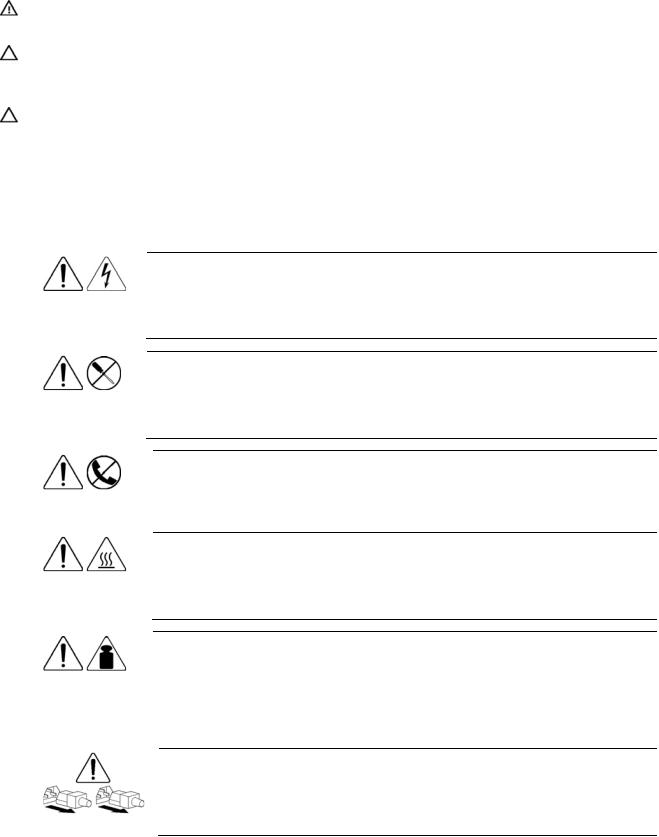
Symbols on equipment
The following symbols may be placed on equipment to indicate the presence of potentially hazardous conditions.
9.43 kg
20.8 lb
This symbol indicates the presence of hazardous energy circuits or electric shock hazards. Refer all servicing to qualified personnel.
WARNING: To reduce the risk of injury from electric shock hazards, do not open this enclosure. Refer all maintenance, upgrades, and servicing to qualified personnel.
This symbol indicates the presence of electric shock hazards. The area contains no user or field serviceable parts. Do not open for any reason.
WARNING: To reduce the risk of injury from electric shock hazards, do not open this enclosure.
This symbol on an RJ-45 receptacle indicates a network interface connection.
WARNING: To reduce the risk of electric shock, fire, or damage to the equipment, do not plug telephone or telecommunications connectors into this receptacle.
This symbol indicates the presence of a hot surface or hot component. If this surface is contacted, the potential for injury exists.
WARNING: To reduce the risk of injury from a hot component, allow the surface to cool before touching.
This symbol indicates that the component exceeds the recommended weight for one individual to handle safely.
WARNING: To reduce the risk of personal injury or damage to the equipment, observe local occupational health and safety requirements and guidelines for manual material handling.
These symbols, on power supplies or systems, indicate that the equipment is supplied by multiple sources of power.
WARNING: To reduce the risk of injury from electric shock, remove all power cords to completely disconnect power from the system.
Removal and replacement procedures 10
Server blade preparation
To service any internal server blade component, power down the server blade and remove it from the server blade enclosure.
CAUTION: Electrostatic discharge (ESD) can damage electronic components. Be sure that you are properly grounded (earthed) before beginning any installation procedure.
System power in server blades does not completely shut off with the front panel power switch or iLO Virtual Power Button feature. The function toggles between on and standby modes, rather than on and off. The standby position removes power from most electronics and the drives, but portions of the power supply and some internal circuitry remain active.
To service internal server blade components:
1.Identify the proper server blade in the server blade enclosure.
2.Back up all server blade data.
3.Power down the server blade in one of the following ways:
•Use the Virtual Power Button feature in the iLO Remote Console to power down the server blade from a remote location. Be sure that the server blade is in standby mode by observing that the power LED is amber.
•Press the power button on the front of the server blade. Be sure that the server blade is in standby mode by observing that the power LED is amber.
4.Remove the server blade from the server blade enclosure.
5.Place the server blade on a flat level surface.
CAUTION: Always populate server blade enclosure bays with either a server blade or server blade blank. Operating the enclosure without a server blade or server blade blank results in improper airflow and improper cooling that can lead to thermal damage.
To install and power up a server blade, reverse the removal procedure. Server blades are set to power up automatically upon insertion. If you have changed this setting, use the power button or iLO Virtual Power Button feature to power up the server blade.
For more information about iLO, refer to the HP Integrated Lights-Out User Guide.
Removal and replacement procedures 11

Access panel
To remove the component:
1.Power down the server blade and remove it from the server blade enclosure ("Server blade preparation" on page 11).
2.Loosen the thumbscrew.
3.Press down on the thumb indentations, slide the access panel toward the rear of the unit about 1.25 cm (0.5 in), and lift to remove the panel.
To replace the component, reverse the removal procedure.
Hard drives
To install the component:
CAUTION: To prevent improper cooling and thermal damage, do not operate the server unless all bays are populated with either a component or a blank.
1.Remove the hard drive blank.
NOTE: Port-colored items indicate hot-plug components.
Removal and replacement procedures 12

2.Install the hard drive.
3.Determine the status of the hard drive from the hot-plug hard drive LEDs ("Hot-plug SCSI hard drive LEDs" on page 37).
Resume normal server operations.
To remove the component, reverse the installation procedure.
DIMMs
To remove the component:
1.Power down the server blade and remove it from the server blade enclosure ("Server blade preparation" on page 11).
2.Remove the access panel ("Access panel" on page 12).
3.Open the DIMM slot latches.
4.Remove the DIMM from the slot.
CAUTION: Use only HP DIMMs. DIMMs from other sources may adversely affect data integrity.
IMPORTANT: For DIMM slots 1 and 2, remove the air baffle, if necessary.
To replace the component, reverse the removal procedure.
Observe the following DIMM installation guidelines:
•All DIMMs must be PC3200 DDR 400-MHz SDRAM DIMMs.
Removal and replacement procedures 13
 Loading...