


ProLiant DL585
Table of contents
 Loading...
HP ProLiant DL585 Generation 2 Server
User Guide
Part Number 431171-002
December 2007 (Second Edition)

© Copyright 2006, 2007 Hewlett-Packard Development Company, L.P.
The information contained herein is subject to change without notice. The only warranties for HP products and services are set forth in the express
warranty statements accompanying such products and services. Nothing herein should be construed as constituting an additional warranty. HP
shall not be liable for technical or editorial errors or omissions contained herein.
Microsoft, Windows, and Windows NT are U.S. registered trademarks of Microsoft Corporation. Windows Server 2003 is a trademark of
Microsoft Corporation.
Audience assumptions
This document is for the person who installs, administers, and troubleshoots servers and storage systems. HP assumes you are qualified in the
servicing of computer equipment and trained in recognizing hazards in products with hazardous energy levels.

Contents 3
Contents
Component identification............................................................................................................... 6
Front panel components ............................................................................................................................. 6
Front panel LEDs and buttons ......................................................................................................................7
Processor memory module components ........................................................................................................8
DIMM slot identification ............................................................................................................................. 9
SAS and SATA hard drive LEDs................................................................................................................... 9
SAS and SATA hard drive LED combinations .............................................................................................. 10
Rear panel components............................................................................................................................ 11
Rear panel LEDs and buttons..................................................................................................................... 12
Internal components................................................................................................................................. 12
System maintenance switch (SW3)................................................................................................... 13
Media board components .............................................................................................................. 14
Boot device selector switch (SW1) ...................................................................................................15
Systems Insight Display LEDs ........................................................................................................... 16
Battery pack LEDs..........................................................................................................................17
Fan locations ................................................................................................................................18
Hot-plug fan LEDs .......................................................................................................................... 19
Hot-plug power supply LEDs...................................................................................................................... 19
Setup......................................................................................................................................... 21
Optional installation services .................................................................................................................... 21
Rack planning resources........................................................................................................................... 21
Optimum environment.............................................................................................................................. 22
Space and airflow requirements ...................................................................................................... 22
Temperature requirements............................................................................................................... 22
Power requirements .......................................................................................................................23
Rack warnings and cautions ..................................................................................................................... 23
Electrical grounding requirements.............................................................................................................. 24
Identifying rack server shipping carton contents........................................................................................... 25
Installing hardware options....................................................................................................................... 25
Installing the server into the rack................................................................................................................ 25
Installing the cable management arm......................................................................................................... 25
Powering up and configuring the server .....................................................................................................25
Installing the operating system................................................................................................................... 26
Registering the server............................................................................................................................... 26
Operations................................................................................................................................. 27
Power up the server................................................................................................................................. 27
Power down the server............................................................................................................................. 27
Extending the server from the rack............................................................................................................. 27
Removing the access panel....................................................................................................................... 28
Accessing the Systems Insight Display ........................................................................................................ 29
Hot-plug fans .......................................................................................................................................... 30
Removing the system battery ..................................................................................................................... 31
Hardware options installation....................................................................................................... 32
Introduction ............................................................................................................................................ 32

Contents 4
Processor options .................................................................................................................................... 32
Removing the processor memory module .......................................................................................... 32
Installing a processor ..................................................................................................................... 34
Memory options...................................................................................................................................... 40
Advanced ECC memory ................................................................................................................. 40
Installing DIMMs ........................................................................................................................... 40
Hard drive guidelines ..............................................................................................................................41
Installing a hot-plug hard drive ........................................................................................................ 42
Installing DVD, CD-ROM, or diskette drives................................................................................................. 43
Hot-plug power supplies........................................................................................................................... 44
Expansion boards ................................................................................................................................... 46
Installing an expansion board ......................................................................................................... 46
Battery-backed write cache....................................................................................................................... 48
Cabling ..................................................................................................................................... 52
Cabling overview.................................................................................................................................... 52
BBWC cabling........................................................................................................................................ 52
Front panel cable components .................................................................................................................. 53
SAS and SATA hard drive cabling............................................................................................................. 53
Software and configuration utilities ............................................................................................... 54
Configuration tools.................................................................................................................................. 54
SmartStart software........................................................................................................................ 54
SmartStart Scripting Toolkit ............................................................................................................. 54
HP ROM-Based Setup Utility............................................................................................................ 55
HP ProLiant Essentials Rapid Deployment Pack ............................................................................................ 56
Option ROM Configuration for Arrays ....................................................................................................... 57
Array Configuration Utility........................................................................................................................ 57
Re-entering the server serial number and product ID..................................................................................... 57
Management tools................................................................................................................................... 58
Automatic Server Recovery .............................................................................................................58
Integrated Lights-Out 2 technology................................................................................................... 58
StorageWorks library and tape tools................................................................................................ 58
Management Agents...................................................................................................................... 59
HP Systems Insight Manager........................................................................................................... 59
Redundant ROM support ................................................................................................................ 59
ROMPaq utility.............................................................................................................................. 60
System Online ROM flash component utility ......................................................................................60
USB support.................................................................................................................................. 60
Diagnostic tools ...................................................................................................................................... 61
HP Insight Diagnostics.................................................................................................................... 61
Integrated Management Log ...........................................................................................................61
Array Diagnostic Utility ..................................................................................................................61
Remote support and analysis tools............................................................................................................. 62
HP Instant Support Enterprise Edition................................................................................................ 62
Keeping the system current ....................................................................................................................... 62
Drivers ......................................................................................................................................... 62
ProLiant Support Packs ................................................................................................................... 62
Operating system version support.................................................................................................... 62
Change control and proactive notification ........................................................................................ 63
Care Pack ....................................................................................................................................63
Troubleshooting.......................................................................................................................... 64
Troubleshooting resources ........................................................................................................................64

Contents 5
Pre-diagnostic steps ................................................................................................................................. 64
Important safety information............................................................................................................ 64
Symptom information ..................................................................................................................... 66
Prepare the server for diagnosis ......................................................................................................67
Loose connections ...................................................................................................................................67
Service notifications................................................................................................................................. 68
Troubleshooting flowcharts .......................................................................................................................68
Start diagnosis flowchart ................................................................................................................68
General diagnosis flowchart ........................................................................................................... 69
Server power-on problems flowchart ................................................................................................71
POST problems flowchart ............................................................................................................... 74
OS boot problems flowchart ...........................................................................................................75
Server fault indications flowchart ..................................................................................................... 77
POST error messages and beep codes....................................................................................................... 79
Regulatory compliance notices ..................................................................................................... 80
Regulatory compliance identification numbers............................................................................................. 80
Federal Communications Commission notice............................................................................................... 80
FCC rating label............................................................................................................................ 80
Class A equipment......................................................................................................................... 80
Class B equipment......................................................................................................................... 80
Declaration of conformity for products marked with the FCC logo, United States only....................................... 81
Modifications.......................................................................................................................................... 81
Cables................................................................................................................................................... 81
Canadian notice (Avis Canadien).............................................................................................................. 82
European Union regulatory notice .............................................................................................................82
Disposal of waste equipment by users in private households in the European Union......................................... 82
Japanese notice ...................................................................................................................................... 83
BSMI notice............................................................................................................................................ 83
Korean notice ......................................................................................................................................... 84
Laser compliance .................................................................................................................................... 84
Battery replacement notice........................................................................................................................ 84
Taiwan battery recycling notice................................................................................................................. 85
Power cord statement for Japan................................................................................................................. 85
Electrostatic discharge................................................................................................................. 86
Preventing electrostatic discharge.............................................................................................................. 86
Grounding methods to prevent electrostatic discharge.................................................................................. 86
Specifications............................................................................................................................. 87
Environmental specifications ..................................................................................................................... 87
Server specifications................................................................................................................................ 87
Technical support........................................................................................................................ 89
Before you contact HP.............................................................................................................................. 89
HP contact information............................................................................................................................. 89
Customer Self Repair ...............................................................................................................................89
Acronyms and abbreviations........................................................................................................ 97
Index....................................................................................................................................... 101
Component identification 6
Component identification
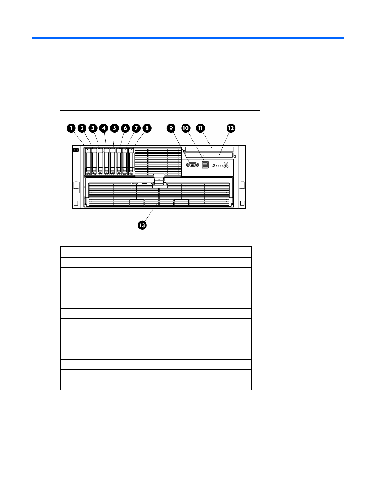
Front panel components
Item Description
1 Hard drive bay 1
2 Hard drive bay 2
3 Hard drive bay 3
4 Hard drive bay 4
5 Hard drive bay 5
6 Hard drive bay 6
7 Hard drive bay 7
8 Hard drive bay 8
9 Video connector
10 USB connectors (two)
11 Media drive blank or optional media drive
12 DVD drive
13 Processor memory module
Component identification 7
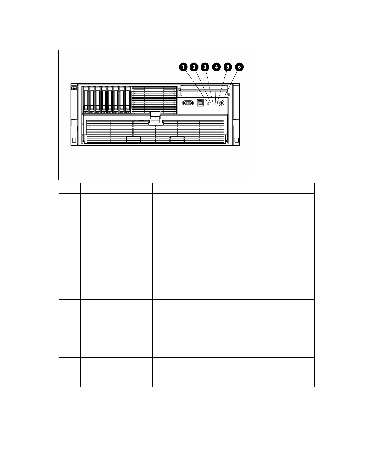
Front panel LEDs and buttons
Item Description Status
1 UID switch and LED Blue = Activated
Flashing blue = Server managed remotely
Off = Deactivated
2 Internal system health LED Green = Normal (system on)
Flashing amber = System health degraded
Flashing red = System health critical
Off = Normal (system off)
3 External system health LED Green = Normal (system on)
Flashing amber = System health degraded
Flashing red = System health critical
Off = Normal (system off)
4 NIC 1 link/activity LED Green = Linked to network
Flashing green = Linked with activity on the network
Off = No network connection
5 NIC 2 link/activity LED Green = Linked to network
Flashing green = Linked with activity on the network
Off = No network connection
6 Power on/Standby button
and LED
Amber = System has AC power and is in standby mode
Green = System has AC power and is turned on
Off = System has no AC power
Component identification 8
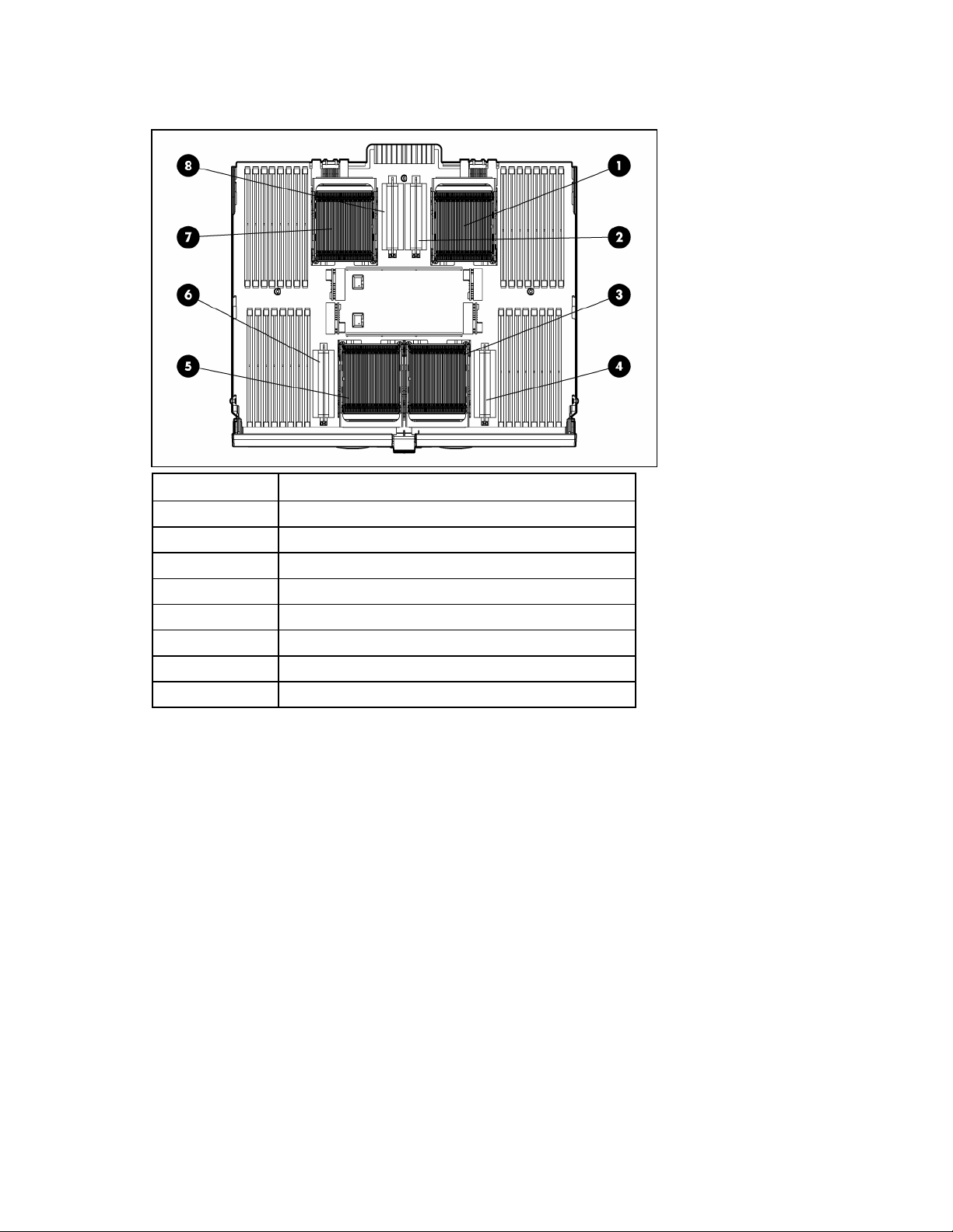
Processor memory module components
Item Description
1 Processor socket 1 (boot processor)
2 PPM socket 1
3 Processor socket 3
4 PPM socket 3
5 Processor socket 4
6 PPM socket 4
7 Processor socket 2
8 PPM socket 2
See "Processor options (on page 32)" for population guidelines.
Component identification 9
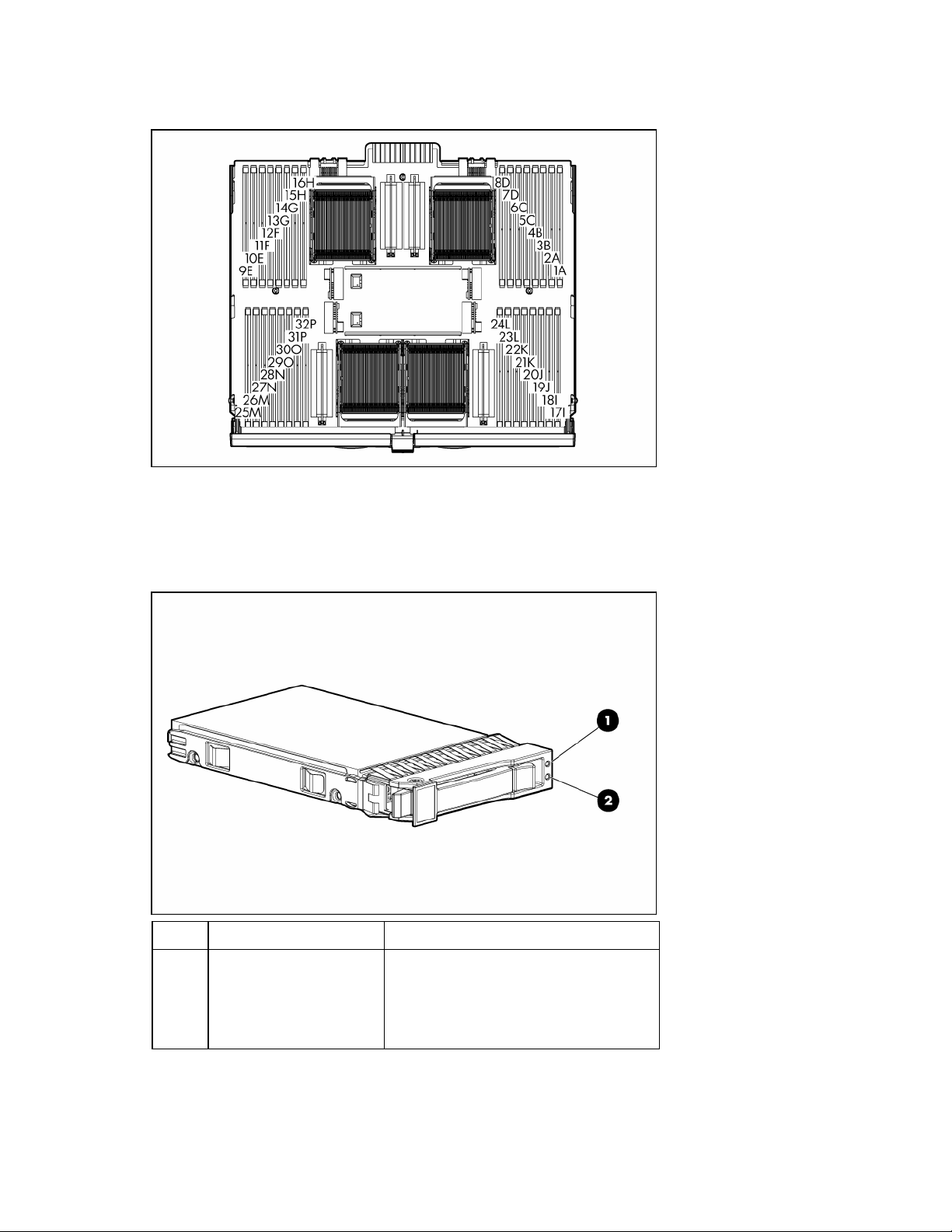
DIMM slot identification
Each memory node consists of eight DIMM slots in four banks. See "Memory options (on page 40)" for
DIMM population guidelines.
SAS and SATA hard drive LEDs
Item Description Status
1 Fault/UID LED Amber = Drive failure
Flashing amber = Fault-process activity
Blue = Unit identification is active
Off = No fault-process activity

Component identification 10
Item Description Status
2 Online/activity LED Green = Drive activity
Flashing green = High activity on the
drive or drive is being configured as part
of an array
Off = No drive activity
SAS and SATA hard drive LED combinations
Online/activity
LED (green)
Fault/UID LED
(amber/blue)
Interpretation
On, off, or
flashing
Alternating amber and
blue
The drive has failed, or a predictive failure alert has been
received for this drive; it also has been selected by a
management application.
On, off, or
flashing
Steadily blue The drive is operating normally, and it has been selected by a
management application.
On Amber, flashing
regularly (1 Hz)
A predictive failure alert has been received for this drive.
Replace the drive as soon as possible.
On Off The drive is online, but it is not active currently.
Flashing regularly
(1 Hz)
Amber, flashing
regularly (1 Hz)
Do not remove the drive. Removing a drive may terminate the
current operation and cause data loss.
The drive is part of an array that is undergoing capacity
expansion or stripe migration, but a predictive failure alert has
been received for this drive. To minimize the risk of data loss,
do not replace the drive until the expansion or migration is
complete.
Flashing regularly
(1 Hz)
Off Do not remove the drive. Removing a drive may terminate the
current operation and cause data loss.
The drive is rebuilding, or it is part of an array that is
undergoing capacity expansion or stripe migration.
Flashing
irregularly
Amber, flashing
regularly (1 Hz)
The drive is active, but a predictive failure alert has been
received for this drive. Replace the drive as soon as possible.
Flashing
irregularly
Off The drive is active, and it is operating normally.
Off Steadily amber A critical fault condition has been identified for this drive, and
the controller has placed it offline. Replace the drive as soon as
possible.
Off Amber, flashing
regularly (1 Hz)
A predictive failure alert has been received for this drive.
Replace the drive as soon as possible.
Off Off The drive is offline, a spare, or not configured as part of an
array.
Component identification 11
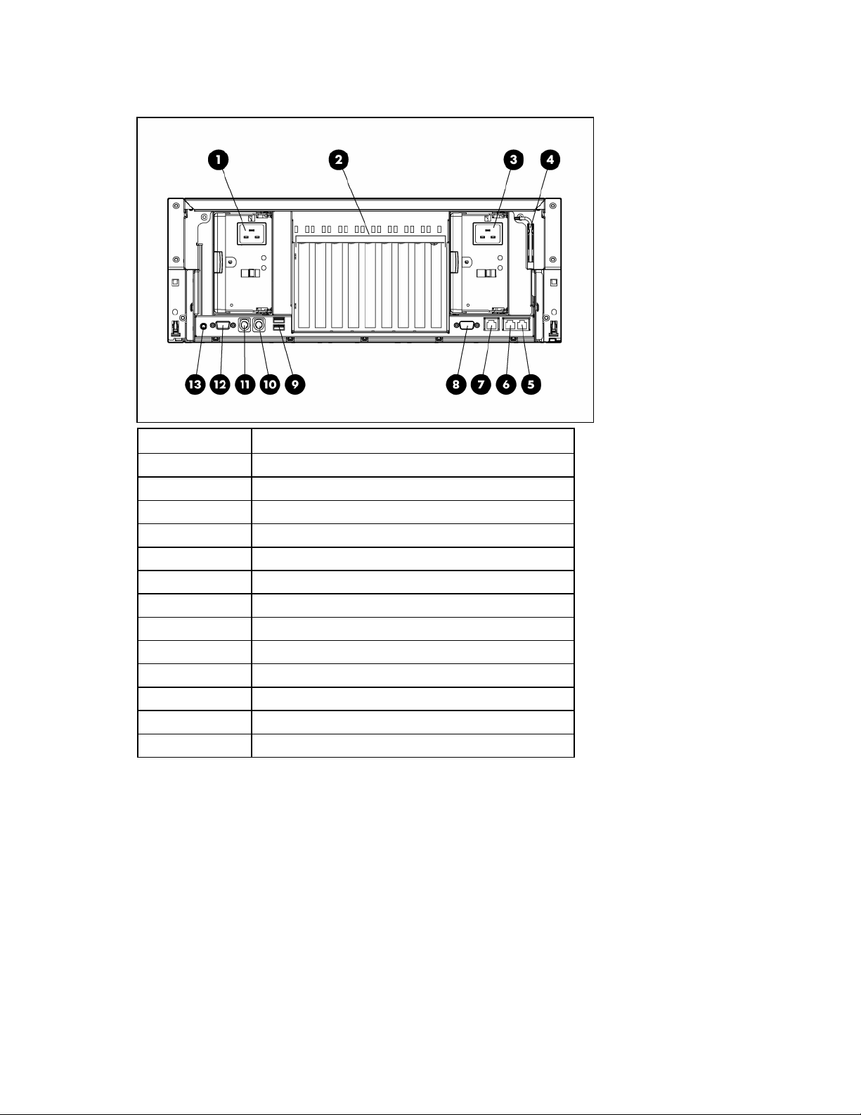
Rear panel components
Item Description
1 Redundant hot-plug power supply (optional)
2 PCI Express and PCI-X non-hot-plug expansion slots
3 Hot-plug power supply (primary)
4 T-15 Torx screwdriver
5 NIC connector 1
6 NIC connector 2
7 iLO 2 connector
8 Serial connector
9 USB connectors (two)
10 Keyboard connector
11 Mouse connector
12 Video connector
13 Rear UID button and LED
See "Expansion boards (on page 46)" for expansion slot definitions.
Component identification 12
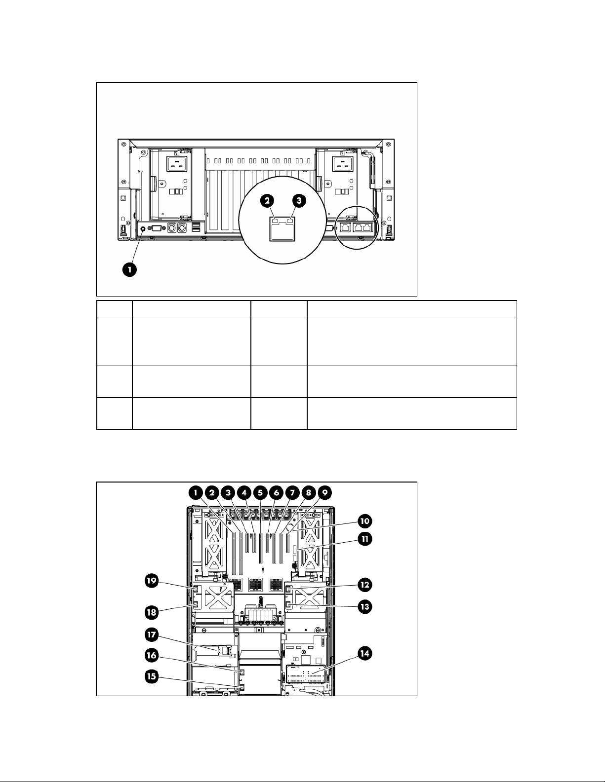
Rear panel LEDs and buttons
Item Description LED color Status
1 UID LED Blue On = Activated
Flashing = Server remotely managed
Off = Deactivated
2 Activity LED Green On or flashing = Network activity
Off = No network activity
3 Link LED Green On = Linked to network
Off = Not linked to network
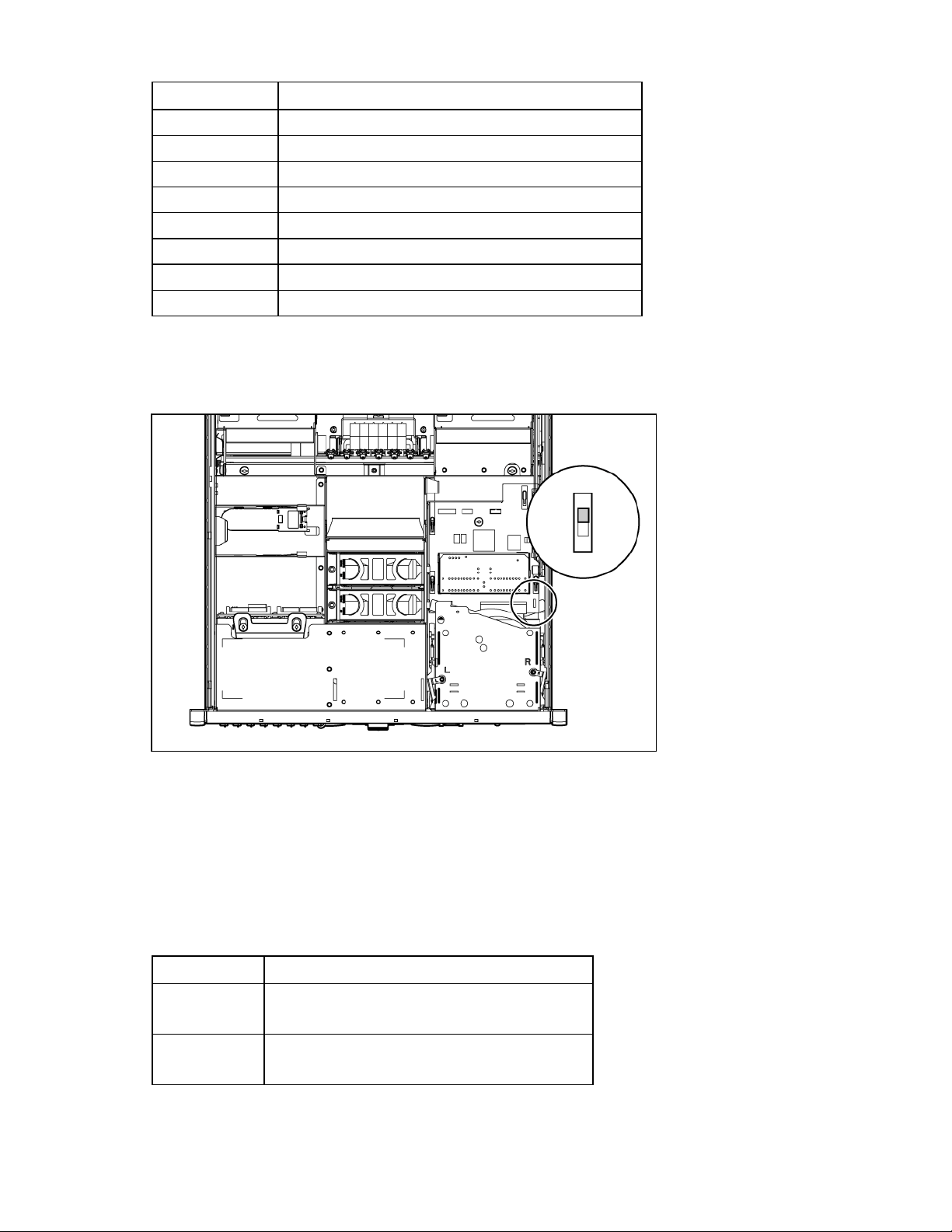
Internal components
Component identification 13
Item Description
1 PCI-X non-hot-plug expansion slot 1, 64-bit/100-MHz
(half-length)
2 PCI-X non-hot-plug expansion slot 2, 64-bit/100-MHz
(full-length)
3 PCI Express x4 non-hot-plug expansion slot 3 (full-length)
4 PCI Express x4 non-hot-plug expansion slot 4 (full-length)
5 PCI Express x8 non-hot-plug expansion slot 5 (full-length)
6 PCI Express x4 non-hot-plug expansion slot 6 (full-length)
7 PCI Express x8 non-hot-plug expansion slot 7 (full-length)
8 PCI Express x8 non-hot-plug expansion slot 8 (full-length)
9 PCI Express x4 non-hot-plug expansion slot 9 (half-length)
10 System battery
11 System maintenance switch (SW3)
12 Fan 6 connector
13 Fan 5 connector
14 Media board
15 Fan 1 connector
16 Fan 2 connector
17 BBWC battery pack
18 Fan 3 connector
19 Fan 4 connector
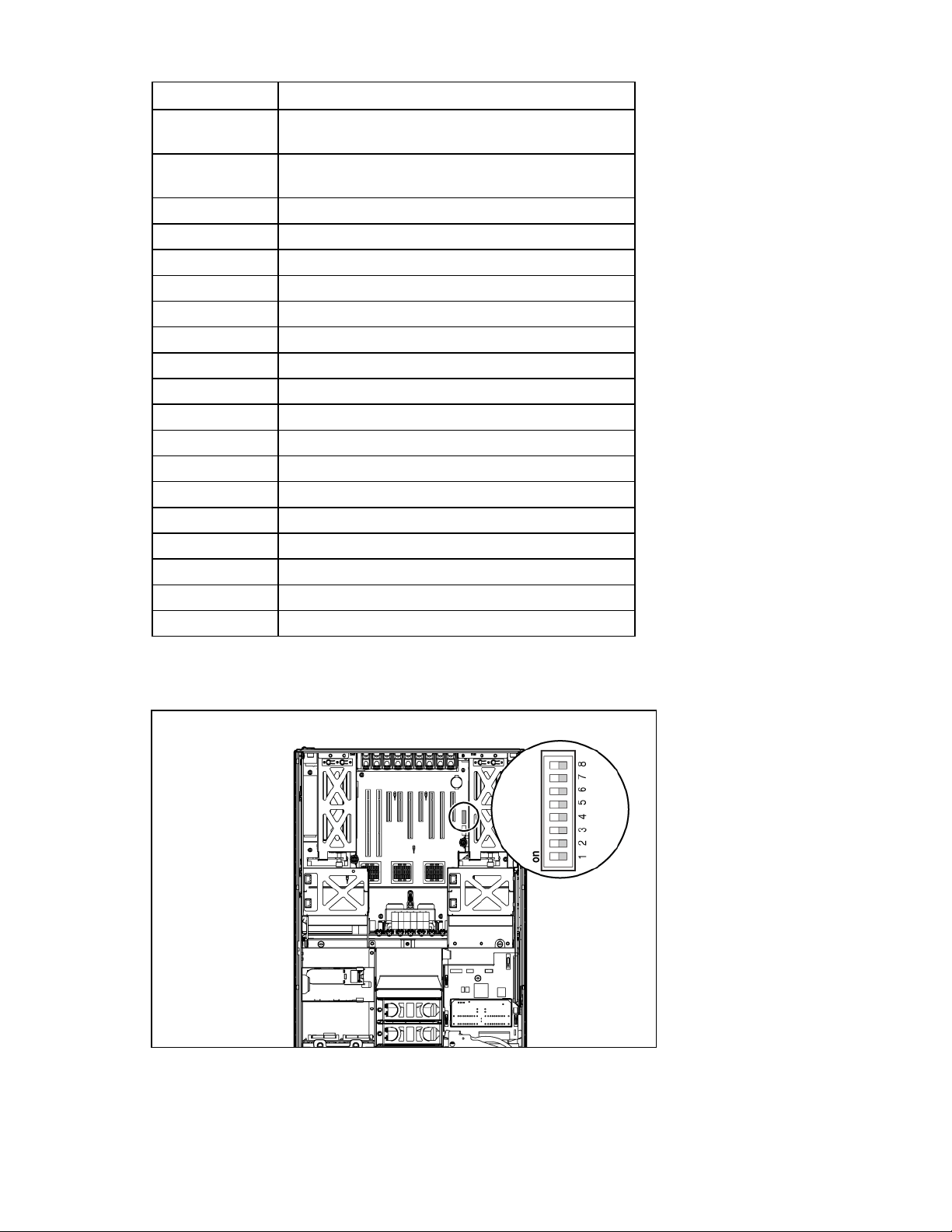
System maintenance switch (SW3)
The system maintenance switch (SW3) is an eight-position switch that is used for system configuration. The
default position for all eight positions is Off (closed).
Component identification 14
Position Description Function
1 iLO 2 security Off = iLO 2 security is
enabled.
On = iLO 2 security is
disabled.
2 Configuration lock Off = System configuration
can be changed.
On = System configuration is
locked.
3 Reserved Reserved
4 Reserved Reserved
5 Password protection
override
Off = Password is enabled.
On = Password is disabled.
6 Configuration validation Off = Switch has no function.
On = Setting clears CMOS
and NVRAM.
7 Reserved Reserved
8 Reserved Reserved
When the system maintenance switch position 6 is set to the On position, the system is prepared to erase
all system configuration settings from both CMOS and NVRAM.
CAUTION: Clearing CMOS and/or NVRAM deletes configuration information. Be sure to
properly configure the server or data loss could occur.
See the HP ProLiant DL585 Generation 2 Server Maintenance and Service Guide on the Documentation
CD for more information.
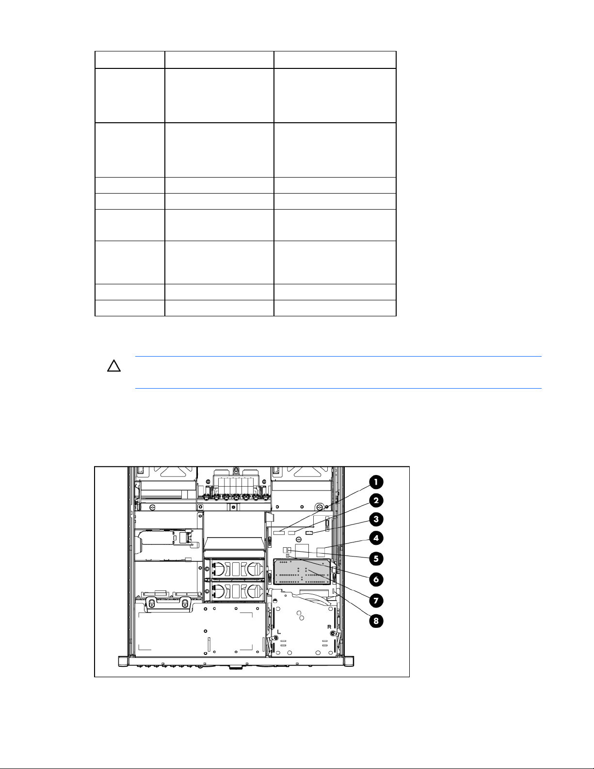
Media board components
Component identification 15
Item Description
1 Power button cable connector
2 USB cable connector
3 Video cable connector
4 Internal USB connector
5 Port 84/85 code display
6 Port 84/85 code display switch
7 System Insight Display
8 Boot device selector switch (SW1)
Boot device selector switch (SW1)
The boot device selector switch setting determines the device access order of the media drives in the
server. The default setting for the boot device selector switch is FLP TOP.
When the boot device selector switch is set to FLP TOP, the optical drive in the bottom bay is designated
as the primary optical drive. The diskette drive in the top bay is bootable. The server cannot boot from a
diskette drive in the bottom bay when the boot device selector switch is set to FLP TOP.
When the boot device selector switch is set to FLP BOT, the optical drive in the top bay is designated as
the primary optical drive. The diskette drive in the bottom bay is bootable. The server cannot boot from a
diskette drive in the top bay when the boot device selector switch is set to FLP BOT.
Switch setting Description
FLP TOP (default) The diskette drive in top bay is bootable.
The primary optical drive in bottom bay is bootable.
FLP BOT The primary optical drive in top bay is bootable.
The diskette drive in bottom bay is bootable.
Component identification 16
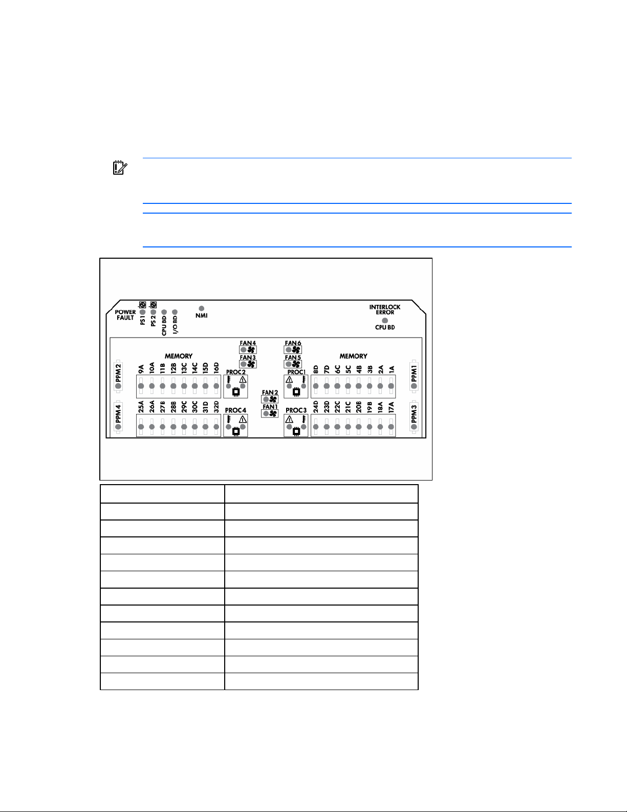
Systems Insight Display LEDs
The front panel health LEDs indicate only the current hardware status. In some situations, HP SIM might
report server status differently than the health LEDs because the software tracks more system attributes. The
System Insight Display LEDs identify components experiencing an error, event, or failure.
The Systems Insight Display LEDs are located on the media board. In normal operations, all of the LEDs
are off unless one of the components fails.
IMPORTANT: When removing the access panel to view the Systems Insight Display LEDs (on
page 16), leave the server powered on. The Systems Insight Display LEDs are cleared when
the server is powered off.
NOTE: The system management driver must be installed for the internal system health LED to
provide pre-failure and warranty conditions.
LED Component
PS1 Power supply (primary)
PS2 Power supply (optional)
CPU BD (Power Fault) Processor memory module board
I/O BD System board
NMI System NMI switch
SLOT X Expansion slot
CPU BD (Interlock Error) System board
PPM X Processor power module
1A–32D DIMM slot
PROC X Processor
FAN X Fan
See the HP ProLiant DL585 Generation 2 Server Maintenance and Service Guide on the Documentation
CD for more information.
Component identification 17
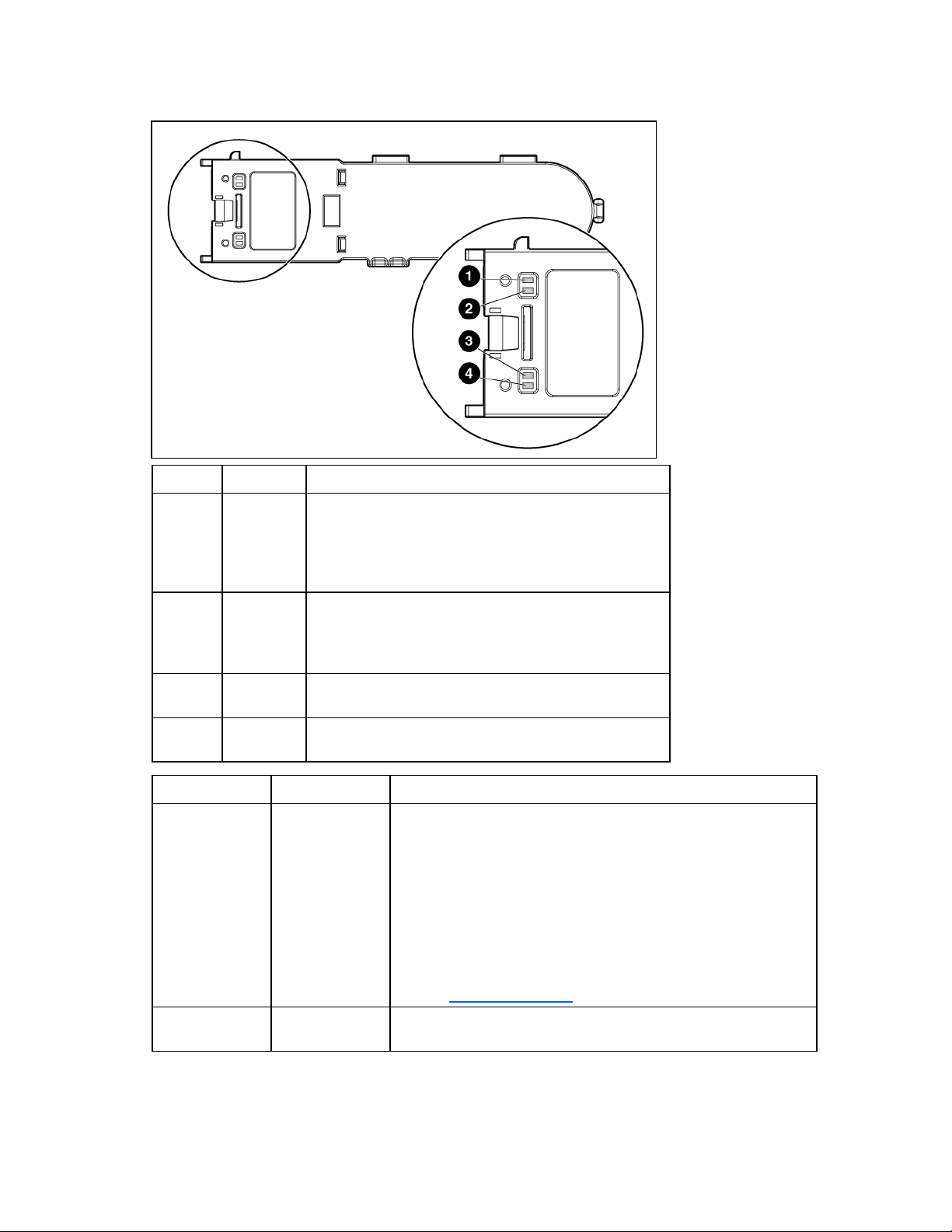
Battery pack LEDs
Item ID Color Description
1 Green System Power LED. This LED glows steadily when the
system is powered up and 12 V system power is
available. This power supply is used to maintain the
battery charge and provide supplementary power to the
cache microcontroller.
2 Green Auxiliary Power LED. This LED glows steadily when 3.3V
auxiliary voltage is detected. The auxiliary voltage is used
to preserve BBWC data and is available any time that the
system power cords are connected to a power supply.
3 Amber Battery Health LED. To interpret the illumination patterns of
this LED, see the following table.
4 Green BBWC Status LED. To interpret the illumination patterns of
this LED, see the following table.
LED3 pattern LED4 pattern Interpretation
— One blink every
two seconds
The system is powered down, and the cache contains data that has
not yet been written to the drives. Restore system power as soon as
possible to prevent data loss.
Data preservation time is extended any time that 3.3 V auxiliary
power is available, as indicated by LED 2. In the absence of
auxiliary power, battery power alone preserves the data. A fully-
charged battery can normally preserve data for at least two days.
The battery lifetime also depends on the cache module size. For
further information, refer to the controller QuickSpecs on the HP
website (http://www.hp.com
).
— Double blink,
then pause
The cache microcontroller is waiting for the host controller to
communicate.
Component identification 18
LED3 pattern LED4 pattern Interpretation
— One blink per
second
The battery pack is below the minimum charge level and is being
charged. Features that require a battery (such as write cache,
capacity expansion, stripe size migration, and RAID migration) are
temporarily unavailable until charging is complete. The recharge
process takes between 15 minutes and two hours, depending on the
initial capacity of the battery.
— Steady glow The battery pack is fully charged, and posted write data is stored in
the cache.
— Off The battery pack is fully charged, and there is no posted write data
in the cache.
One blink per
second
One blink per
second
An alternating green and amber blink pattern indicates that the
cache microcontroller is executing from within its boot loader and
receiving new flash code from the host controller.
Steady glow — There is a short circuit across the battery terminals or within the
battery pack. BBWC features are disabled until the battery pack is
replaced. The life expectancy of a battery pack is typically more
than three years.
One blink per
second
— There is an open circuit across the battery terminals or within the
battery pack. BBWC features are disabled until the battery pack is
replaced. The life expectancy of a battery pack is typically more
than three years.
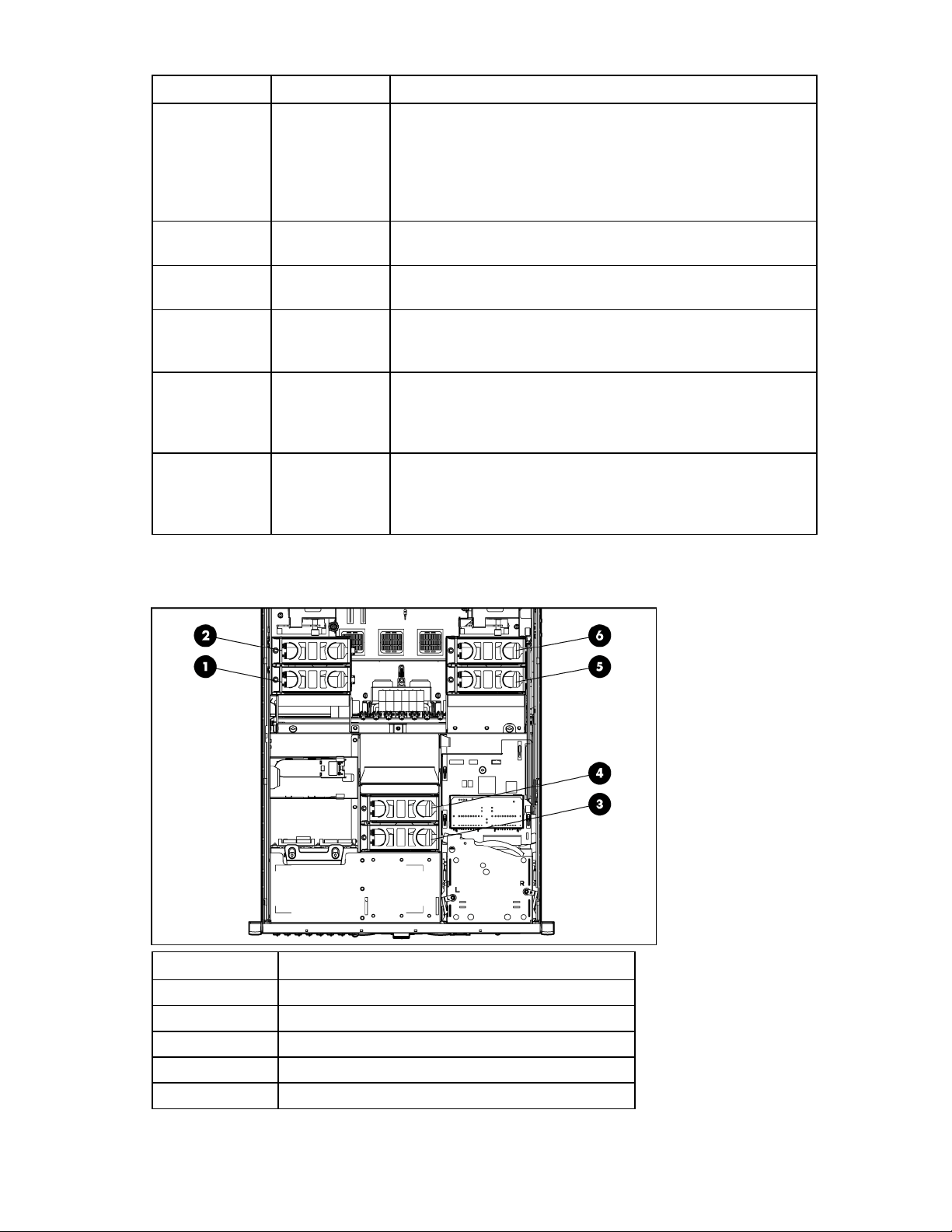
Fan locations
Item Description
1 Fan 3
2 Fan 4
3 Fan 1
4 Fan 2
5 Fan 5
Component identification 19
Item Description
6 Fan 6
See "Hot-plug fans (on page 30)" for replacement procedures and operation guidelines.
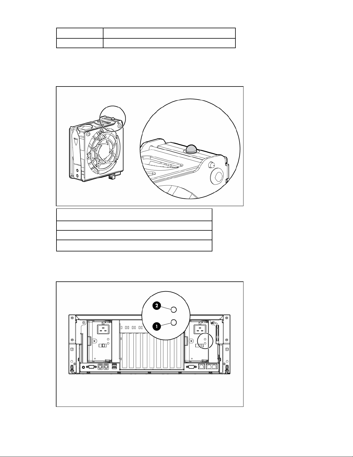
Hot-plug fan LEDs
Status
Green = Operating normally
Amber = Failed
Off = No power
Hot-plug power supply LEDs

Component identification 20
Fail LED 1
(amber)
Power LED 2
(green)
Description
Off Off No AC power to any power supply
Flashing Off Power supply failure (over current)
On Off No AC power to this power supply
Off Flashing
• AC power present
• Standby mode
Off On Normal

Setup 21
Setup
Optional installation services
Delivered by experienced, certified engineers, HP Care Pack services help you keep your servers up and
running with support packages tailored specifically for HP ProLiant systems. HP Care Packs let you
integrate both hardware and software support into a single package. A number of service level options
are available to meet your needs.
HP Care Pack Services offer upgraded service levels to expand your standard product warranty with easy-
to-buy, easy-to-use support packages that help you make the most of your server investments. Some of the
Care Pack services are:
• Hardware support
o 6-Hour Call-to-Repair
o 4-Hour 24x7 Same Day
o 4-Hour Same Business Day
• Software support
o Microsoft®
o Linux
o HP ProLiant Essentials (HP SIM and RDP)
o VMWare
• Integrated hardware and software support
o Critical Service
o Proactive 24
o Support Plus
o Support Plus 24
• Startup and implementation services for both hardware and software
For more information on Care Packs, refer to the HP website
(http://www.hp.com/hps/carepack/servers/cp_proliant.html
).
Rack planning resources
The rack resource kit ships with all HP branded or Compaq branded 9000, 10000, and H9 series racks.
For more information on the content of each resource, refer to the rack resource kit documentation.
If you intend to deploy and configure multiple servers in a single rack, refer to the white paper on high-
density deployment at the HP website (http://www.hp.com/products/servers/platforms
).

Setup 22
Optimum environment
When installing the server, select a location that meets the environmental standards described in this
section.
Space and airflow requirements
To allow for servicing and adequate airflow, observe the following space and airflow requirements when
deciding where to install a rack:
• Leave a minimum clearance of 63.5 cm (25 in) in front of the rack.
• Leave a minimum clearance of 76.2 cm (30 in) behind the rack.
• Leave a minimum clearance of 121.9 cm (48 in) from the back of the rack to the back of another
rack or row of racks.
HP servers draw in cool air through the front door and expel warm air through the rear door. Therefore,
the front and rear rack doors must be adequately ventilated to allow ambient room air to enter the
cabinet, and the rear door must be adequately ventilated to allow the warm air to escape from the
cabinet.
CAUTION: To prevent improper cooling and damage to the equipment, do not block the
ventilation openings.
When vertical space in the rack is not filled by a server or rack component, the gaps between the
components cause changes in airflow through the rack and across the servers. Cover all gaps with
blanking panels to maintain proper airflow.
CAUTION: Always use blanking panels to fill empty vertical spaces in the rack. This
arrangement ensures proper airflow. Using a rack without blanking panels results in improper
cooling that can lead to thermal damage.
The 9000 and 10000 Series Racks provide proper server cooling from flow-through perforations in the
front and rear doors that provide 64 percent open area for ventilation.
CAUTION: When using a Compaq branded 7000 Series rack, you must install the high
airflow rack door insert [P/N 327281-B21 (42U) or P/N 157847-B21 (22U)] to provide
proper front-to-back airflow and cooling.
CAUTION: If a third-party rack is used, observe the following additional requirements to ensure
adequate airflow and to prevent damage to the equipment:
• Front and rear doors—If the 42U rack includes closing front and rear doors, you must allow
5,350 sq cm (830 sq in) of holes evenly distributed from top to bottom to permit adequate
airflow (equivalent to the required 64 percent open area for ventilation).
• Side—The clearance between the installed rack component and the side panels of the rack
must be a minimum of 7 cm (2.75 in).
Temperature requirements
To ensure continued safe and reliable equipment operation, install or position the system in a well-
ventilated, climate-controlled environment.

Setup 23
The maximum recommended ambient operating temperature (TMRA) for most server products is 35°C
(95°F). The temperature in the room where the rack is located must not exceed 35°C (95°F).
CAUTION: To reduce the risk of damage to the equipment when installing third-party options:
• Do not permit optional equipment to impede airflow around the server or to increase the
internal rack temperature beyond the maximum allowable limits.
• Do not exceed the manufacturer’s TMRA.
Power requirements
Installation of this equipment must comply with local and regional electrical regulations governing the
installation of information technology equipment by licensed electricians. This equipment is designed to
operate in installations covered by NFPA 70, 1999 Edition (National Electric Code) and NFPA-75, 1992
(code for Protection of Electronic Computer/Data Processing Equipment). For electrical power ratings on
options, refer to the product rating label or the user documentation supplied with that option.
WARNING: To reduce the risk of personal injury, fire, or damage to the equipment, do not
overload the AC supply branch circuit that provides power to the rack. Consult the electrical
authority having jurisdiction over wiring and installation requirements of your facility.
CAUTION: Protect the server from power fluctuations and temporary interruptions with a
regulating uninterruptible power supply (UPS). This device protects the hardware from damage
caused by power surges and voltage spikes and keeps the system in operation during a power
failure.
When installing more than one server, you may need to use additional power distribution devices to
safely provide power to all devices. Observe the following guidelines:
• Balance the server power load between available AC supply branch circuits.
• Do not allow the overall system AC current load to exceed 80 percent of the branch circuit AC
current rating.
• Do not use common power outlet strips for this equipment.
• Provide a separate electrical circuit for the server.
Rack warnings and cautions
WARNING: To reduce the risk of personal injury or damage to the equipment, be sure that:
• The leveling jacks are extended to the floor.
• The full weight of the rack rests on the leveling jacks.
• The stabilizing feet are attached to the rack if it is a single-rack installation.
• The racks are coupled together in multiple-rack installations.
• Only one component is extended at a time. A rack may become unstable if more than one
component is extended for any reason.

Setup 24
WARNING: To reduce the risk of personal injury or equipment damage when unloading a
rack:
• At least two people are needed to safely unload the rack from the pallet. An empty 42U
rack can weigh as much as 115 kg (253 lb), can stand more than 2.1 m (7 ft) tall, and
may become unstable when being moved on its casters.
• Never stand in front of the rack when it is rolling down the ramp from the pallet. Always
handle the rack from both sides.
WARNING: When installing a server in a telco rack, be sure that the rack frame is adequately
secured to the top and bottom of the building structure.
WARNING: This server is very heavy. To reduce the risk of personal injury or damage to the
equipment:
• Observe local occupational health and safety requirements and guidelines for manual
material handling.
• Get help to lift and stabilize the product during installation or removal, especially when the
product is not fastened to the rails. When the server weighs more than 22.5 kg (50 lb), at
least two people must lift the server into the rack together. A third person may be required
to help align the server if the server is installed higher than chest level.
• Use caution when installing the server in or removing the server from the rack; it is unstable
when not fastened to the rails.
WARNING: To reduce the risk of personal injury from hot surfaces, allow the drives and the
internal system components to cool before touching them.
WARNING: To reduce the risk of personal injury, electric shock, or damage to the equipment,
remove the power cord to remove power from the server. The front panel Power On/Standby
button does not completely shut off system power. Portions of the power supply and some
internal circuitry remain active until AC power is removed.
CAUTION: Protect the server from power fluctuations and temporary interruptions with a
regulating uninterruptible power supply (UPS). This device protects the hardware from damage
caused by power surges and voltage spikes and keeps the system in operation during a power
failure.
CAUTION: Do not operate the server for long periods with the access panel open or removed.
Operating the server in this manner results in improper airflow and improper cooling that can
lead to thermal damage.
Electrical grounding requirements
The server must be grounded properly for proper operation and safety. In the United States, you must
install the equipment in accordance with NFPA 70, 1999 Edition (National Electric Code), Article 250,
as well as any local and regional building codes. In Canada, you must install the equipment in
accordance with Canadian Standards Association, CSA C22.1, Canadian Electrical Code. In all other
countries, you must install the equipment in accordance with any regional or national electrical wiring
codes, such as the International Electrotechnical Commission (IEC) Code 364, parts 1 through 7.

Setup 25
Furthermore, you must be sure that all power distribution devices used in the installation, such as branch
wiring and receptacles, are listed or certified grounding-type devices.
Because of the high ground-leakage currents associated with multiple servers connected to the same
power source, HP recommends the use of a PDU that is either permanently wired to the building’s branch
circuit or includes a nondetachable cord that is wired to an industrial-style plug. NEMA locking-style plugs
or those complying with IEC 60309 are considered suitable for this purpose. Using common power outlet
strips for the server is not recommended.
Identifying rack server shipping carton contents
Unpack the server shipping carton and locate the materials and documentation necessary for installing the
server. All the rack mounting hardware necessary for installing the server into the rack is included with the
rack or the server.
The contents of the server shipping carton include:
• Server
• Power cord
• Hardware documentation, Documentation CD, and software products
• Rack-mounting hardware
In addition to the supplied items, you may need:
• Hardware options
• Operating system or application software
• PDU
Installing hardware options
Install any hardware options before initializing the server. For options installation information, refer to the
option documentation. For server-specific information, refer to "Hardware options installation (on page
32)."
Installing the server into the rack
Refer to the installation instructions that ship with the rack kit to install the server into the rack.
Installing the cable management arm
Refer to the installation instructions that ship with the rack kit to install the cable management arm.
Powering up and configuring the server
To power up the server, press the Power On/Standby button.
During the initial boot, the server configuration automatically defaults to prepare for operating system
installation.

Setup 26
To modify the server default settings, press the F9 key when prompted during the boot process to enter
RBSU. By default, RBSU runs in the English language.
NOTE: If an HP array controller has been added or is embedded in the system, the array
controller will default to a RAID configuration based on the size and number of hard drives
installed. Press the F8 key when prompted during the array controller initialization to use the
ORCA utility to modify the controller default settings.
For more information on the automatic configuration, see the HP ROM-Based Setup Utility User Guide on
the Documentation CD.
Installing the operating system
To operate properly, the server must have a supported operating system. For the latest information on
operating system support, see the HP website (http://www.hp.com/go/supportos
).
Three methods are available to install an operating system on the server:
• SmartStart assisted installation—Insert the SmartStart CD into an external USB CD-ROM drive, and
then reboot the server.
• Manual installation—Insert the operating system CD into an external USB CD-ROM drive, and then
reboot the server. This process might require you to obtain additional drivers from the HP website
(http://www.hp.com/support
).
• Remote deployment installation—The operating system can be remotely deployed using the Rapid
Deployment Pack (RDP) or PXE boot over an Ethernet connection.
Follow the on-screen instructions to begin the installation process.
For information on using these installation methods, see the SmartStart installation poster in the HP
ProLiant Essentials Foundation Pack, included with the server.
Registering the server
To register the server, refer to the HP Registration website (http://register.hp.com).

Operations 27
Operations
Power up the server
To power up the server, press the Power On/Standby button.
Power down the server
WARNING: To reduce the risk of personal injury, electric shock, or damage to the equipment,
remove the power cord to remove power from the server. The front panel Power On/Standby
button does not completely shut off system power. Portions of the power supply and some
internal circuitry remain active until AC power is removed.
IMPORTANT: If installing a hot-plug device, it is not necessary to power down the server.
1. Shut down the OS as directed by the OS documentation.
2. Press the Power On/Standby button to place the server in standby mode. When the server enters
standby power mode, the system power LED changes to amber.
3. Disconnect the power cords.
The system is now without power.
Extending the server from the rack
The design of the server enables you to access several components through the front of the server.
Installing or accessing the following components will not require extending the server from the rack:
• Processors
• PPMs
• Processor memory board
• DIMMs
• DVD drive
• Optional diskette or CD-ROM drive
• Hard drives
To extend the server from the rack:
1. Pull down the quick-release levers on each side of the server to release the server from the rack.
2. Extend the server on the rack rails until the server rail-release latches engage.
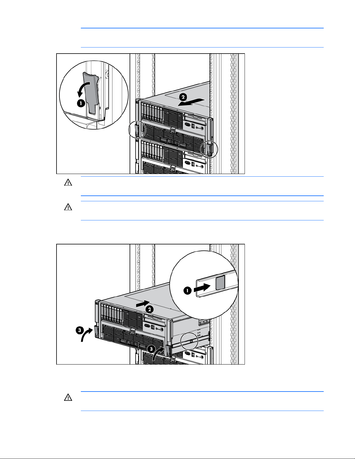
Operations 28
NOTE: The release latches will lock into place when the rails are fully extended.
WARNING: To reduce the risk of personal injury or equipment damage, be sure that the rack
is adequately stabilized before extending a component from the rack.
WARNING: To reduce the risk of personal injury, be careful when pressing the server rail-
release latches and sliding the server into the rack. The sliding rails could pinch your fingers.
3. After performing the installation or maintenance procedure, slide the server into the rack by pressing
the server rail-release latches.
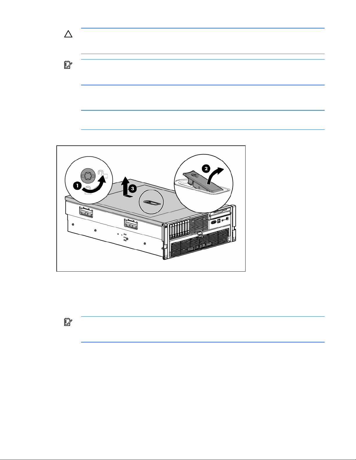
Removing the access panel
WARNING: To reduce the risk of personal injury from hot surfaces, allow the drives and the
internal system components to cool before touching them.
Operations 29
CAUTION: Do not operate the server for long periods with the access panel open or removed.
Operating the server in this manner results in improper airflow and improper cooling that can
lead to thermal damage.
IMPORTANT: When removing the access panel to view the Systems Insight Display LEDs (on
page 16), leave the server powered on. The Systems Insight Display LEDs are cleared when
the server is powered off.
1. Extend the server from the rack ("Extending the server from the rack" on page 27).
2. If the locking latch is locked, use a T-15 Torx screwdriver to unlock the latch.
NOTE: The T-15 Torx screwdriver is shipped with the server and can be located on the rear
panel ("Rear panel components" on page 11).
3. Lift up on the hood latch, and remove the access panel.
4. After installing hardware options, replace the access panel. Be sure that the panel is securely locked
into place before powering up the server.
Accessing the Systems Insight Display
IMPORTANT: When removing the access panel to view the Systems Insight Display LEDs (on
page 16), leave the server powered on. The Systems Insight Display LEDs are cleared when
the server is powered off.
1. Extend the server from the rack ("Extending the server from the rack" on page 27).
2. Remove the access panel ("Removing the access panel" on page 28).
3. Locate the Systems Insight Display ("Media board components" on page 14).
Operations 30
Hot-plug fans
The server supports redundant hot-plug fans ("Fan locations" on page 18) in a 5+1 configuration to
provide proper airflow to the server.
WARNING: To prevent personal injury from hazardous energy:
• Remove watches, rings, or other metal objects.
• Use tools with insulated handles.
• Do not place tools or metal parts on top of batteries.
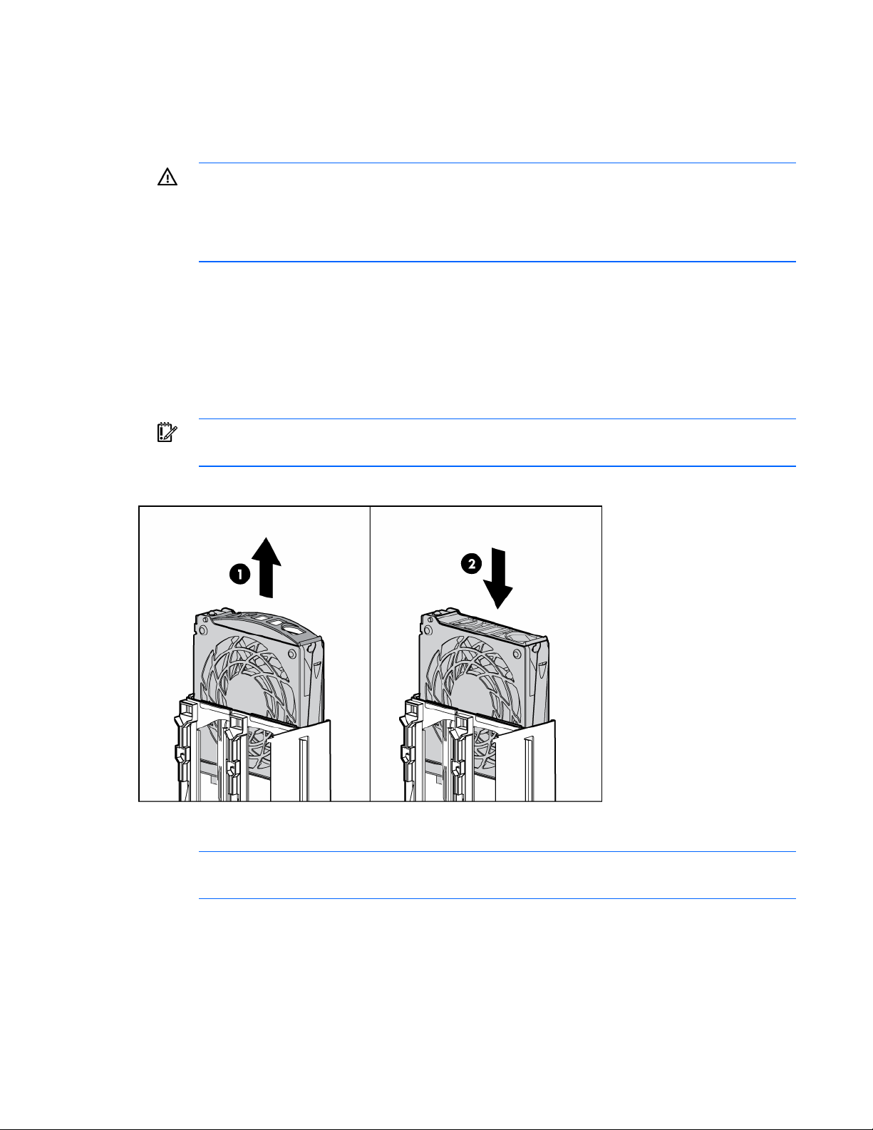
To replace a hot-plug fan:
1. Extend the server from the rack ("Extending the server from the rack" on page 27).
2. Remove the access panel ("Removing the access panel" on page 28).
3. Identify the failed fan by locating an amber LED on top of the failed fan ("Hot-plug fan LEDs" on
page 19) or on the Systems Insight Display ("Systems Insight Display LEDs" on page 16).
4. Remove the malfunctioning hot-plug fan from the server.
IMPORTANT: Remove and replace one fan at a time. If the system detects two fan failures, the
server shuts down to avoid thermal damage.
5. Install a new hot-plug fan.
6. Observe the LED on each installed fan to be sure it is illuminated green ("Hot-plug fan LEDs" on
page 19).
NOTE: If the front panel internal system health LED is not green after you install hot-plug fans,
reseat the hot-plug fan or refer to the troubleshooting section.
7. Replace the access panel ("Removing the access panel" on page 28).
8. Slide the server into the rack.
Loading...