


 Loading...
HP QV997AV, 8300E, D8C24UT, 8300, D3K66UT User Manual
...HP Compaq Business PC Maintenance
and Service Guide
Elite 8300 Series Convertible Minitower
Elite 8300 Series Microtower
Elite 8300 Series Small Form Factor
Elite 8300 Series Ultra-Slim Desktop
© Copyright 2012 Hewlett-Packard Development Company, L.P. The information contained herein is subject to change without notice.
Microsoft, Windows, and Windows Vista are either trademarks or registered trademarks of Microsoft Corporation in the United States and/or other countries.
The only warranties for HP products and services are set forth in the express warranty statements accompanying such products and services. Nothing herein should be construed as constituting an additional warranty. HP shall not be liable for technical or editorial errors or omissions contained herein.
This document contains proprietary information that is protected by copyright. No part of this document may be photocopied, reproduced, or translated to another language without the prior written consent of Hewlett-Packard Company.
Second Edition (December 2012)
First Edition (May 2012)
Document Part Number: 690355-002

About This Book
WARNING! Text set off in this manner indicates that failure to follow directions could result in bodily harm or loss of life.
CAUTION: Text set off in this manner indicates that failure to follow directions could result in damage to equipment or loss of information.
 NOTE: Text set off in this manner provides important supplemental information.
iii
iv About This Book

Table of contents
1 Product Features ............................................................................................................................................ |
1 |
Standard Configuration Features ......................................................................................................... |
1 |
Convertible Minitower (CMT) Front Panel Components ....................................................................... |
3 |
Microtower (MT) Front Panel Components .......................................................................................... |
4 |
Small Form Factor (SFF) Front Panel Components ............................................................................. |
5 |
Ultra-Slim Desktop (USDT) Front Panel Components ......................................................................... |
6 |
Convertible Minitower (CMT) Rear Panel Components ....................................................................... |
7 |
Microtower (MT) Rear Panel Components ........................................................................................... |
8 |
Small Form Factor (SFF) Rear Panel Components ............................................................................. |
9 |
Ultra-Slim Desktop (USDT) Rear Panel Components ........................................................................ |
10 |
Serial Number Location ...................................................................................................................... |
11 |
2 Activating and Customizing the Software .................................................................................................. |
13 |
Activating and customizing the software in Windows 7 ...................................................................... |
13 |
Activating the Windows operating system ......................................................................... |
13 |
Downloading Windows 7 updates ...................................................................................... |
14 |
Installing or upgrading device drivers ................................................................................ |
14 |
Customizing the monitor display ........................................................................................ |
14 |
Activating and customizing the software in Windows 8 ...................................................................... |
14 |
Activating the Windows Operating System ........................................................................ |
14 |
Downloading Windows 8 updates ...................................................................................... |
15 |
Customizing the monitor display ........................................................................................ |
15 |
3 Computer Setup (F10) Utility ....................................................................................................................... |
16 |
Computer Setup (F10) Utilities ........................................................................................................... |
16 |
Using Computer Setup (F10) Utilities ................................................................................ |
17 |
Computer Setup—File ....................................................................................................... |
18 |
Computer Setup—Storage ................................................................................................ |
19 |
Computer Setup—Security ................................................................................................ |
22 |
Computer Setup—Power ................................................................................................... |
27 |
Computer Setup—Advanced ............................................................................................. |
28 |
v
Recovering the Configuration Settings ............................................................................................... |
30 |
4 Illustrated parts catalog ............................................................................................................................... |
31 |
Convertible minitower (CMT) chassis spare parts .............................................................................. |
31 |
Computer system components .......................................................................................... |
31 |
Cables ................................................................................................................................ |
33 |
Misc parts .......................................................................................................................... |
34 |
Drives ................................................................................................................................. |
35 |
Misc boards ....................................................................................................................... |
36 |
Sequential part number listing ........................................................................................... |
36 |
Microtower (MT) chassis spare parts ................................................................................................. |
40 |
Computer major components ............................................................................................ |
40 |
Cables ................................................................................................................................ |
42 |
Misc parts .......................................................................................................................... |
43 |
Drives ................................................................................................................................. |
44 |
Misc boards ....................................................................................................................... |
45 |
Sequential part number listing ........................................................................................... |
45 |
Small Form Factor (SFF) chassis spare parts .................................................................................... |
49 |
Computer major components ............................................................................................ |
49 |
Cables ................................................................................................................................ |
51 |
Misc parts .......................................................................................................................... |
52 |
Drives ................................................................................................................................. |
54 |
Misc boards ....................................................................................................................... |
54 |
Sequential part number listing ........................................................................................... |
55 |
Ultra-Slim Desktop (USDT) chassis spare parts ................................................................................ |
58 |
Computer major components ............................................................................................ |
58 |
Cables ................................................................................................................................ |
59 |
Misc parts .......................................................................................................................... |
60 |
Drives ................................................................................................................................. |
62 |
Misc boards ....................................................................................................................... |
62 |
Sequential part number listing ........................................................................................... |
62 |
5 Routine Care, SATA Drive Guidelines, and Disassembly Preparation .................................................... |
66 |
Electrostatic Discharge Information .................................................................................................... |
66 |
Generating Static ............................................................................................................... |
66 |
Preventing Electrostatic Damage to Equipment ................................................................ |
67 |
Personal Grounding Methods and Equipment ................................................................... |
67 |
Grounding the Work Area .................................................................................................. |
68 |
Recommended Materials and Equipment .......................................................................... |
68 |
Operating Guidelines .......................................................................................................................... |
69 |
Routine Care ...................................................................................................................................... |
69 |
vi
General Cleaning Safety Precautions ................................................................................ |
69 |
Cleaning the Computer Case ............................................................................................ |
69 |
Cleaning the Keyboard ...................................................................................................... |
70 |
Cleaning the Monitor .......................................................................................................... |
70 |
Cleaning the Mouse ........................................................................................................... |
71 |
Service Considerations ...................................................................................................................... |
71 |
Power Supply Fan ............................................................................................................. |
71 |
Tools and Software Requirements .................................................................................... |
71 |
Screws ............................................................................................................................... |
71 |
Cables and Connectors ..................................................................................................... |
72 |
Hard Drives ........................................................................................................................ |
72 |
Lithium Coin Cell Battery ................................................................................................... |
72 |
SATA Hard Drives .............................................................................................................................. |
73 |
SATA Hard Drive Cables .................................................................................................................... |
73 |
SATA Data Cable .............................................................................................................. |
73 |
SMART ATA Drives ............................................................................................................................ |
73 |
Cable Management ............................................................................................................................ |
73 |
6 Removal and Replacement Procedures Convertible Minitower (CMT) Chassis ..................................... |
75 |
Preparation for Disassembly .............................................................................................................. |
75 |
Access Panel ...................................................................................................................................... |
76 |
Front Bezel ......................................................................................................................................... |
77 |
Front Bezel Security ........................................................................................................................... |
78 |
Bezel Blanks ....................................................................................................................................... |
80 |
System Board Connections ................................................................................................................ |
81 |
Memory .............................................................................................................................................. |
82 |
DIMMs ............................................................................................................................... |
82 |
DDR3-SDRAM DIMMs ...................................................................................................... |
82 |
Populating DIMM Sockets ................................................................................................. |
83 |
Installing DIMMs ................................................................................................................ |
84 |
Expansion Card .................................................................................................................................. |
85 |
Drives ................................................................................................................................................. |
89 |
Drive Positions ................................................................................................................... |
90 |
Removing a Drive from a Drive Bay .................................................................................. |
91 |
Installing Drives ................................................................................................................. |
95 |
Installing a 5.25-inch Drive into a Drive Bay ..................................................... |
97 |
Installing a Hard Drive into an Internal Drive Bay ............................................. |
99 |
Hood Sensor .................................................................................................................................... |
104 |
Front I/O, USB Assembly ................................................................................................................. |
105 |
Power Switch Assembly ................................................................................................................... |
107 |
Speaker ............................................................................................................................................ |
108 |
vii
Rear Chassis Fan ............................................................................................................................. |
109 |
Fan sink ............................................................................................................................................ |
110 |
Processor ......................................................................................................................................... |
112 |
Power Supply ................................................................................................................................... |
115 |
System Board ................................................................................................................................... |
116 |
Changing from a Minitower to a Desktop Configuration ................................................................... |
117 |
Changing from a Desktop to a Minitower Configuration ................................................................... |
119 |
7 Removal and Replacement Procedures Microtower (MT) Chassis ........................................................ |
122 |
Preparation for Disassembly ............................................................................................................ |
122 |
Computer Access Panel ................................................................................................................... |
123 |
Front Bezel ....................................................................................................................................... |
124 |
Front Bezel Security ......................................................................................................................... |
125 |
Bezel Blanks ..................................................................................................................................... |
127 |
Memory ............................................................................................................................................ |
128 |
DIMMs ............................................................................................................................. |
128 |
DDR3-SDRAM DIMMs .................................................................................................... |
128 |
Populating DIMM Sockets ............................................................................................... |
128 |
Installing DIMMs .............................................................................................................. |
129 |
Expansion Cards .............................................................................................................................. |
130 |
System Board Connections .............................................................................................................. |
136 |
Drives ............................................................................................................................................... |
138 |
Drive Positions ................................................................................................................. |
140 |
Removing a 5.25-inch or 3.5-inch Drive from a Drive Bay ............................................... |
140 |
Installing a 5.25-inch or 3.5-inch Drive into a Drive Bay .................................................. |
142 |
Removing a Hard Drive from a Drive Bay ........................................................................ |
144 |
Installing a Hard Drive into an Internal Drive Bay ............................................................ |
144 |
Front Fan Assembly ......................................................................................................................... |
147 |
Front I/O Assembly ........................................................................................................................... |
149 |
Power Switch/LED Assembly ........................................................................................................... |
150 |
Heat sink .......................................................................................................................................... |
151 |
Processor ......................................................................................................................................... |
153 |
Speaker ............................................................................................................................................ |
156 |
Rear Chassis Fan ............................................................................................................................. |
157 |
Power Supply ................................................................................................................................... |
159 |
System Board ................................................................................................................................... |
161 |
8 Removal and Replacement Procedures Small Form Factor (SFF) Chassis .......................................... |
163 |
Preparation for Disassembly ............................................................................................................ |
163 |
Access Panel .................................................................................................................................... |
164 |
Front Bezel ....................................................................................................................................... |
165 |
viii
Front Bezel Security ......................................................................................................................... |
166 |
Bezel Blanks ..................................................................................................................................... |
168 |
Memory ............................................................................................................................................ |
169 |
DIMMs ............................................................................................................................. |
169 |
DDR3-SDRAM DIMMs .................................................................................................... |
169 |
Populating DIMM Sockets ............................................................................................... |
169 |
Installing DIMMs .............................................................................................................. |
170 |
Expansion Card ................................................................................................................................ |
172 |
System Board Connections .............................................................................................................. |
177 |
Drives ............................................................................................................................................... |
178 |
Drive Positions ................................................................................................................. |
178 |
Installing and Removing Drives ....................................................................................... |
179 |
Removing a 5.25-inch Drive from a Drive Bay ................................................ |
180 |
Installing a 5.25-inch Drive into a Drive Bay ................................................... |
181 |
Removing a 3.5-inch Drive from a Drive Bay .................................................. |
184 |
Installing a 3.5-inch Drive into a Drive Bay ..................................................... |
185 |
Removing and Replacing the Primary 3.5-inch Internal Hard Drive ................ |
187 |
Fan duct ........................................................................................................................................... |
190 |
Front Fan Assembly ......................................................................................................................... |
191 |
Hood Sensor .................................................................................................................................... |
193 |
Front I/O, Power Switch Assembly ................................................................................................... |
194 |
Speaker ............................................................................................................................................ |
196 |
Heat sink .......................................................................................................................................... |
197 |
Processor ......................................................................................................................................... |
198 |
Power Supply ................................................................................................................................... |
202 |
System Board ................................................................................................................................... |
204 |
Using the Small Form Factor Computer in a Tower Orientation ...................................................... |
206 |
9 Removal and Replacement Procedures Ultra-Slim Desktop (USDT) Chassis ...................................... |
207 |
Preparation for Disassembly ............................................................................................................ |
207 |
Access Panel .................................................................................................................................... |
208 |
Front Bezel ....................................................................................................................................... |
209 |
Front Bezel Security ......................................................................................................................... |
210 |
Bezel Blank ...................................................................................................................................... |
212 |
System Board Connections .............................................................................................................. |
213 |
Memory ............................................................................................................................................ |
214 |
SODIMMs ........................................................................................................................ |
214 |
DDR3-SDRAM SODIMMs ............................................................................................... |
214 |
Populating SODIMM Sockets .......................................................................................... |
215 |
Installing SODIMMs ......................................................................................................... |
216 |
Front Fan .......................................................................................................................................... |
218 |
ix
Optical Drive ..................................................................................................................................... |
219 |
Removing the Optical Drive ............................................................................................. |
219 |
Preparing the New Optical Drive ..................................................................................... |
220 |
Installing the New Optical Drive ....................................................................................... |
221 |
Hard Drive ........................................................................................................................................ |
222 |
Optical Drive Rail .............................................................................................................................. |
227 |
Card Reader ..................................................................................................................................... |
228 |
Speaker ............................................................................................................................................ |
230 |
Heat sink .......................................................................................................................................... |
231 |
Processor ......................................................................................................................................... |
233 |
WLAN Module .................................................................................................................................. |
236 |
Hood Sensor .................................................................................................................................... |
238 |
Graphics Board ................................................................................................................................ |
239 |
System Board ................................................................................................................................... |
241 |
Rear Fan .......................................................................................................................................... |
243 |
Antennas .......................................................................................................................................... |
244 |
Changing from Desktop to Tower Configuration .............................................................................. |
248 |
Port Cover ........................................................................................................................................ |
249 |
Power Supply, External .................................................................................................................... |
250 |
10 Troubleshooting Without Diagnostics .................................................................................................... |
251 |
Safety and Comfort .......................................................................................................................... |
251 |
Before You Call for Technical Support ............................................................................................. |
251 |
Helpful Hints ..................................................................................................................................... |
252 |
Solving General Problems ................................................................................................................ |
254 |
Solving Power Problems .................................................................................................................. |
258 |
Solving Hard Drive Problems ........................................................................................................... |
260 |
Solving Media Card Reader Problems ............................................................................................. |
263 |
Solving Display Problems ................................................................................................................. |
265 |
Solving Audio Problems ................................................................................................................... |
270 |
Solving Printer Problems .................................................................................................................. |
272 |
Solving Keyboard and Mouse Problems .......................................................................................... |
274 |
Solving Hardware Installation Problems ........................................................................................... |
276 |
Solving Network Problems ............................................................................................................... |
278 |
Solving Memory Problems ............................................................................................................... |
281 |
Solving Processor Problems ............................................................................................................ |
283 |
Solving CD-ROM and DVD Problems .............................................................................................. |
283 |
Solving USB Flash Drive Problems .................................................................................................. |
285 |
Solving Front Panel Component Problems ...................................................................................... |
287 |
Solving Internet Access Problems .................................................................................................... |
287 |
Solving Software Problems .............................................................................................................. |
289 |
x
Contacting Customer Support .......................................................................................................... |
291 |
11 POST Error Messages .............................................................................................................................. |
292 |
POST Numeric Codes and Text Messages ..................................................................................... |
293 |
Interpreting POST Diagnostic Front Panel LEDs and Audible Codes .............................................. |
301 |
12 Password Security and Resetting CMOS ............................................................................................... |
305 |
Resetting the Password Jumper ...................................................................................................... |
306 |
Clearing and Resetting the CMOS ................................................................................................... |
307 |
13 HP PC Hardware Diagnostics .................................................................................................................. |
309 |
Why run HP PC Hardware Diagnostics – UEFI ................................................................................ |
309 |
How to access and run HP PC Hardware Diagnostics - UEFI ......................................................... |
309 |
Downloading HP PC Hardware Diagnostics to a USB device .......................................................... |
310 |
14 Backup and Recovery .............................................................................................................................. |
311 |
Restoring and recovering in Windows 7 ........................................................................................... |
311 |
System Restore ............................................................................................................... |
311 |
System Recovery ............................................................................................................. |
311 |
System Recovery when Windows is responding ............................................ |
312 |
System Recovery when Windows is not responding ...................................... |
313 |
System recovery using recovery media .......................................................... |
313 |
Creating recovery media ................................................................ |
314 |
Using recovery media ..................................................................... |
315 |
Backup and recovery in Windows 8 ................................................................................................. |
316 |
Backing up your information ............................................................................................ |
316 |
Performing a system recovery ......................................................................................... |
317 |
Using the Windows recovery tools .................................................................. |
317 |
Using f11 recovery tools .................................................................................. |
318 |
Using Windows 8 operating system media (purchased separately) ............... |
318 |
Appendix A Battery Replacement ................................................................................................................ |
319 |
Appendix B Removing and Replacing a Removable 3.5-inch SATA Hard Drive ..................................... |
322 |
Appendix C Unlocking the Smart Cover Lock ............................................................................................ |
327 |
Smart Cover FailSafe Key ................................................................................................................ |
327 |
Using the Smart Cover FailSafe Key to Remove the Smart Cover Lock ......................................... |
328 |
xi
Appendix D Power Cord Set Requirements ................................................................................................ |
330 |
General Requirements ..................................................................................................................... |
330 |
Japanese Power Cord Requirements .............................................................................................. |
330 |
Country-Specific Requirements ........................................................................................................ |
331 |
Appendix E Specifications ............................................................................................................................ |
332 |
CMT Specifications .......................................................................................................................... |
332 |
MT Specifications ............................................................................................................................. |
333 |
SFF Specifications ........................................................................................................................... |
335 |
USDT Specifications ........................................................................................................................ |
336 |
Index ................................................................................................................................................................. |
337 |
xii

1 Product Features
Standard Configuration Features
Features may vary depending on the model. For a complete listing of the hardware and software installed in the computer, run the diagnostic utility (included on some computer models only).
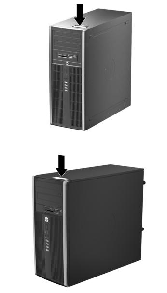
Figure 1-1 Convertible Minitower Configuration


 NOTE: The HP Compaq Convertible Minitower computer can be easily converted to a desktop. For more information, see Changing from a Minitower to a Desktop Configuration on page 117 in this guide.
Figure 1-2 Microtower Configuration
Standard Configuration Features |
1 |
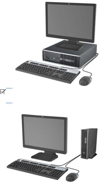
Figure 1-3 Small Form Factor Configuration


 NOTE: The Small Form Factor computer can also be used in a tower orientation. For more information, see Using the Small Form Factor Computer in a Tower Orientation on page 206 in this guide.
Figure 1-4 Ultra-Slim Desktop Configuration
2 Chapter 1 Product Features
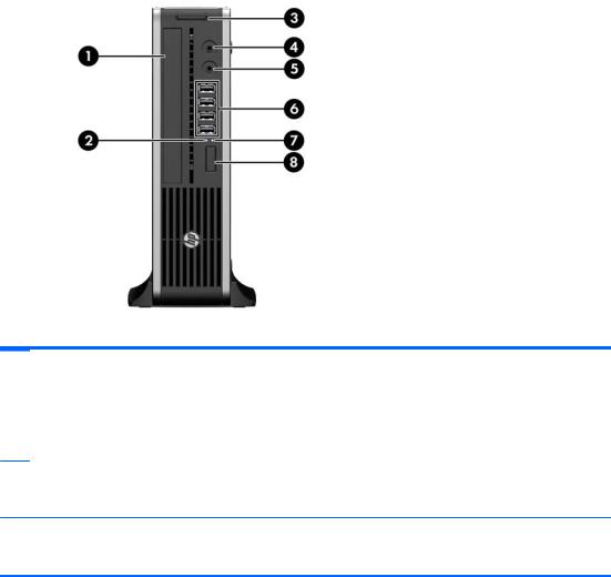
Convertible Minitower (CMT) Front Panel Components
Drive configuration may vary by model. Some models have a bezel blank covering one or more drive bays.
Figure 1-5 Front Panel Components
Table 1-1 Front Panel Components
1 |
5.25-inch Optical Drives |
5 |
Microphone/Headphone Connector |
|
|
|
|
2 |
5.25-inch Media Card Reader (optional) |
6 |
Power On Light |
|
|
|
|
3 |
Dual-State Power Button |
7 |
Headphone Connector |
|
|
|
|
4 |
Hard Drive Activity Light |
8 |
USB (Universal Serial Bus) Ports |
NOTE: When a device is plugged into the Microphone/Headphone Connector, a dialog box will pop up asking if you want to use the connector for a microphone Line-In device or a headphone. You can reconfigure the connector at any time by double-clicking the Realtek HD Audio Manager icon in the Windows taskbar.
NOTE: The Power On Light is normally green when the power is on. If it is flashing red, there is a problem with the computer and it is displaying a diagnostic code. Refer to Interpreting POST Diagnostic Front Panel LEDs and Audible Codes on page 301 to interpret the code.
Convertible Minitower (CMT) Front Panel Components |
3 |
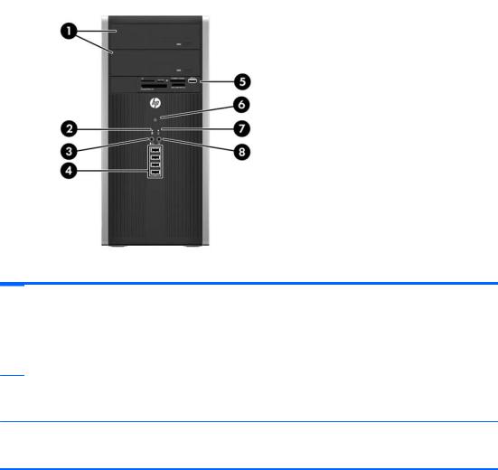
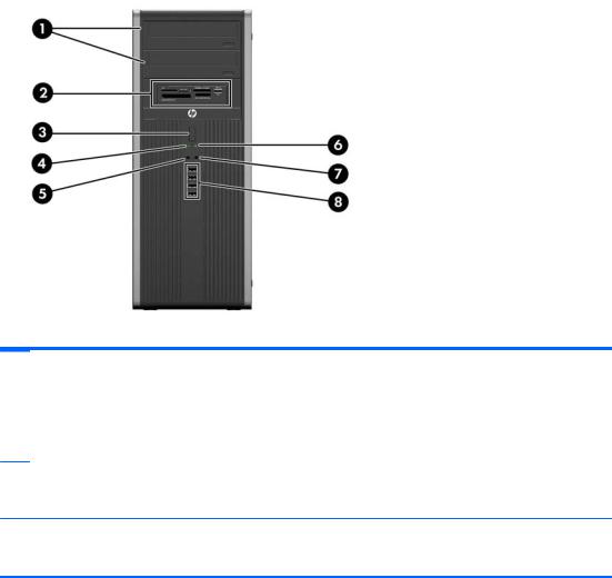
Microtower (MT) Front Panel Components
Drive configuration may vary by model. Some models have a bezel blank covering one or more drive bays.
Table 1-2 Front Panel Components
1 |
5.25-inch Optical Drives |
5 |
3.5-inch Media Card Reader (optional) |
|
|
|
|
2 |
Hard Drive Activity Light |
6 |
Dual-State Power Button |
|
|
|
|
3 |
Microphone/Headphone Connector |
7 |
Power On Light |
|
|
|
|
4 |
USB (Universal Serial Bus) 2.0 Ports |
8 |
Headphone Connector |
NOTE: When a device is plugged into the Microphone/Headphone Connector, a dialog box will pop up asking if you want to use the connector for a microphone Line-In device or a headphone. You can reconfigure the connector at any time by double-clicking the Realtek HD Audio Manager icon in the Windows taskbar.
NOTE: The Power On Light is normally green when the power is on. If it is flashing red, there is a problem with the computer and it is displaying a diagnostic code. Refer to Interpreting POST Diagnostic Front Panel LEDs and Audible Codes on page 301 to interpret the code.
4 Chapter 1 Product Features
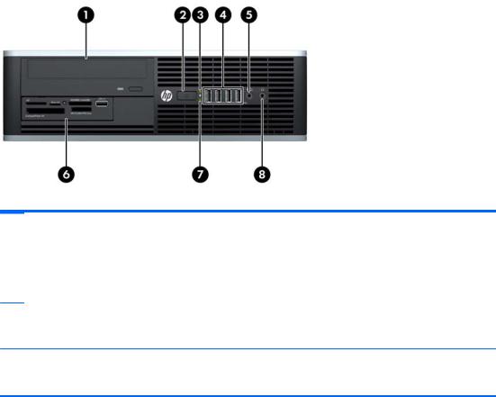
Small Form Factor (SFF) Front Panel Components
Drive configuration may vary by model. Some models have a bezel blank covering one or more drive bays.
Figure 1-6 Front Panel Components
Table 1-3 Front Panel Components
1 |
5.25-inch Optical Drive |
5 |
Microphone/Headphone Connector |
|
|
|
|
2 |
Dual-State Power Button |
6 |
3.5-inch Media Card Reader (optional) |
|
|
|
|
3 |
Power On Light |
7 |
Hard Drive Activity Light |
|
|
|
|
4 |
USB (Universal Serial Bus) Ports |
8 |
Headphone Connector |
NOTE: When a device is plugged into the Microphone/Headphone Connector, a dialog box will pop up asking if you want to use the connector for a microphone Line-In device or a headphone. You can reconfigure the connector at any time by double-clicking the Realtek HD Audio Manager icon in the Windows taskbar.
NOTE: The Power On Light is normally green when the power is on. If it is flashing red, there is a problem with the computer and it is displaying a diagnostic code. Refer toInterpreting POST Diagnostic Front Panel LEDs and Audible Codes on page 301 to interpret the code.
Small Form Factor (SFF) Front Panel Components |
5 |
Ultra-Slim Desktop (USDT) Front Panel Components
Drive configuration may vary by model. Some models have a bezel blank covering the optical drive bay.
Figure 1-7 Front Panel Components
Table 1-4 Front Panel Components
1 |
Optical Drive |
5 |
Microphone/Headphone Connector |
|
|
|
|
2 |
Power On Light |
6 |
USB (Universal Serial Bus) Ports |
|
|
|
|
3 |
SD Media Card Reader (optional) |
7 |
Hard Drive Activity Light |
|
|
|
|
4 |
Headphone Connector |
8 |
Dual-State Power Button |
NOTE: When a device is plugged into the Microphone/Headphone Connector, a dialog box will pop up asking if you want to use the connector for a microphone Line-In device or a headphone. You can reconfigure the connector at any time by double-clicking the Realtek HD Audio Manager icon in the Windows taskbar.
NOTE: The Power On Light is normally green when the power is on. If it is flashing red, there is a problem with the computer and it is displaying a diagnostic code. Refer to Interpreting POST Diagnostic Front Panel LEDs and Audible Codes on page 301 to interpret the code.
6 Chapter 1 Product Features
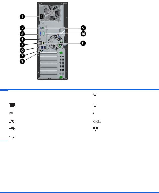
Convertible Minitower (CMT) Rear Panel Components
Figure 1-8 Rear Panel Components
Table 1-5 Rear Panel Components
1 |
Power Cord Connector |
7 |
Line-Out Connector for powered audio |
|
|
|
devices (green) |
|
|
|
|
2 |
PS/2 Keyboard Connector (purple) |
8 |
Line-In Audio Connector (blue) |
|
|
|
|
3 |
VGA Monitor Connector |
9 |
PS/2 Mouse Connector (green) |
|
|
|
|
4 |
DisplayPort Monitor Connector |
10 |
Serial Connector |
|
|
|
|
5 |
USB 2.0 ports (black) |
11 |
RJ-45 Network Connector |
|
|
|
|
6 |
USB 3.0 ports (blue) |
|
|
NOTE: USB 3.0 ports are blue; USB 2.0 ports are black.
An optional second serial port and an optional parallel port are available from HP.
When a device is plugged into the blue Line-In Audio Connector, a dialog box will pop up asking if you want to use the connector for a line-in device or a microphone. You can reconfigure the connector at any time by doubleclicking the Realtek HD Audio Manager icon in the Windows taskbar.
The monitor connectors on the system board are inactive when a graphics card is installed in the computer.
If a graphics card is installed into one of the system board slots, the connectors on the graphics card and the system board may be used at the same time. Some settings may need to be changed in Computer Setup to use both connectors.
Convertible Minitower (CMT) Rear Panel Components |
7 |
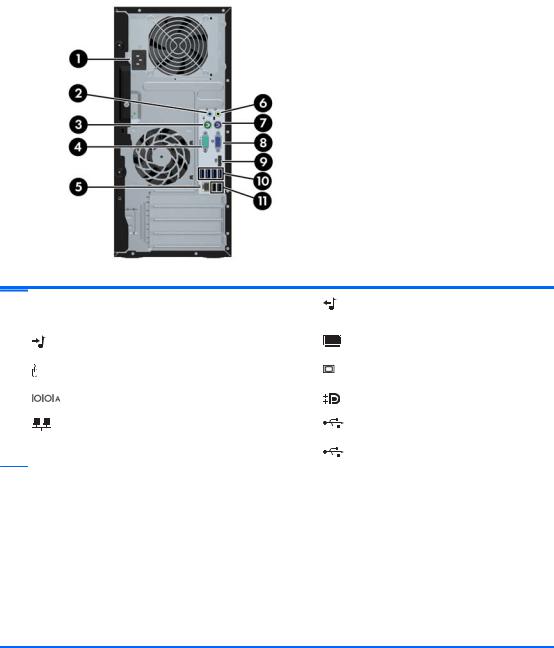
Microtower (MT) Rear Panel Components
Figure 1-9 Rear Panel Components
Table 1-6 Rear Panel Components
1 |
Power Cord Connector |
6 |
Line-Out Connector for powered audio |
|
|
|
devices (green) |
|
|
|
|
2 |
Line-In Audio Connector (blue) |
7 |
PS/2 Keyboard Connector (purple) |
|
|
|
|
3 |
PS/2 Mouse Connector (green) |
8 |
VGA Monitor Connector |
|
|
|
|
4 |
Serial Connector |
9 |
DisplayPort Monitor Connector |
|
|
|
|
5 |
RJ-45 Network Connector |
10 |
USB 3.0 ports (blue) |
|
|
|
|
|
|
11 |
USB 2.0 ports (black) |
NOTE: USB 3.0 ports are blue; USB 2.0 ports are black.
An optional second serial port and an optional parallel port are available from HP.
When a device is plugged into the blue Line-In Audio Connector, a dialog box will pop up asking if you want to use the connector for a line-in device or a microphone. You can reconfigure the connector at any time by doubleclicking the Realtek HD Audio Manager icon in the Windows taskbar.
The monitor connectors on the system board are inactive when a graphics card is installed in the computer.
If a graphics card is installed into one of the motherboard slots, the connectors on the graphics card and the system board may be used at the same time. Some settings may need to be changed in Computer Setup to use both connectors.
8 Chapter 1 Product Features
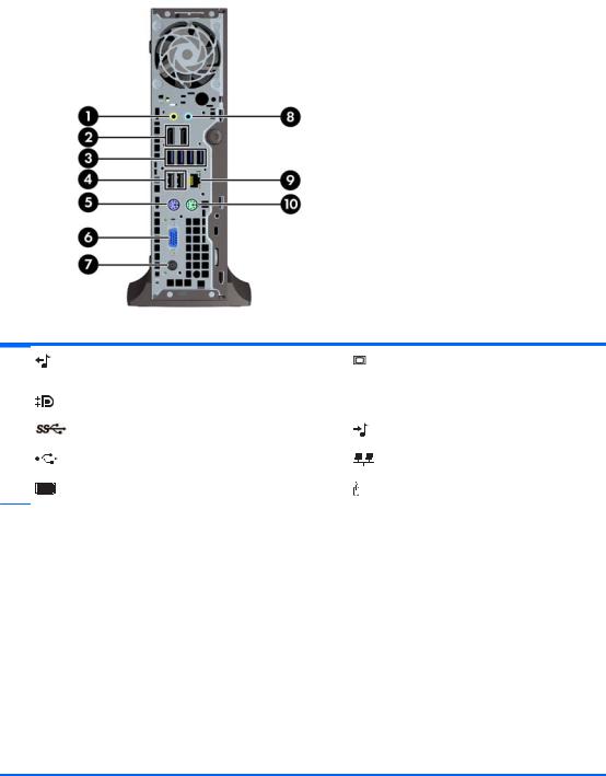
Small Form Factor (SFF) Rear Panel Components
Figure 1-10 Rear Panel Components
1 |
RJ-45 Network Connector |
7 |
DisplayPort Monitor Connector |
|
|
|
|
2 |
Serial Connector |
8 |
VGA Monitor Connector |
|
|
|
|
3 |
PS/2 Mouse Connector (green) |
9 |
PS/2 Keyboard Connector (purple) |
|
|
|
|
4 |
Power Cord Connector |
10 |
Line-Out Connector for powered audio |
|
|
|
devices (green) |
|
|
|
|
5 |
USB 2.0 ports (black) |
11 |
Line-In Audio Connector (blue) |
|
|
|
|
6 |
USB 3.0 ports (blue) |
|
|
NOTE: USB 3.0 ports are blue; USB 2.0 ports are black.
An optional second serial port and an optional parallel port are available from HP.
When a device is plugged into the blue Line-In Audio Connector, a dialog box will pop up asking if you want to use the connector for a line-in device or a microphone. You can reconfigure the connector at any time by doubleclicking the Realtek HD Audio Manager icon in the Windows taskbar.
The monitor connectors on the system board are inactive when a graphics card is installed in the computer.
If a graphics card is installed into one of the motherboard slots, the connectors on the graphics card and the system board may be used at the same time. Some settings may need to be changed in Computer Setup to use both connectors.
Small Form Factor (SFF) Rear Panel Components |
9 |
Ultra-Slim Desktop (USDT) Rear Panel Components
Figure 1-11 Rear Panel Components
Table 1-7 Rear Panel Components
1 |
Line-Out Connector for powered audio |
6 |
VGA Monitor Connector |
|
devices (green) |
|
|
|
|
|
|
2 |
DisplayPort Monitor Connectors |
7 |
Power Cord Connector |
|
|
|
|
3 |
USB 3.0 ports (blue) |
8 |
Line-In Audio Connector (blue) |
|
|
|
|
4 |
USB 2.0 ports (black) |
9 |
RJ-45 Network Connector |
|
|
|
|
5 |
PS/2 Keyboard Connector (purple) |
10 |
PS/2 Mouse Connector (green) |
NOTE: USB 3.0 ports are blue; USB 2.0 ports are black.
If an MXM graphics card is installed, all three monitor ports are active. The integrated graphics operate DisplayPort2 (top port). The MXM/ATI drivers operate DisplayPort1 (bottom port) and VGA. If the integrated graphics are disabled in the BIOS settings, DisplayPort2 (top port) will not be active.
If an MXM graphics card is not installed, all three monitor ports are driven by the integrated graphics on the Intel 3rd Generation configurations. On some models, all three monitor ports are active but there are some limitations. For example, if a DisplayPort to DVI or HDMI adapter is installed, the VGA port will not be active. On other models, only one DisplayPort can be active. Either DisplayPort will function, but only one can be used.
When a DisplayPort to single-link DVI or DisplayPort to HDMI adapter is installed, the VGA port will not be active. This is because when one of the above adapters is used, it is not considered a true DisplayPort and will function as the other type of port. This is not an issue with a DisplayPort to dual-link DVI adapter.
When a device is plugged into the blue Line-In Audio Connector, a dialog box will pop up asking if you want to use the connector for a line-in device or a microphone. You can reconfigure the connector at any time by doubleclicking the Realtek HD Audio Manager icon in the Windows taskbar.
10 Chapter 1 Product Features
Serial Number Location
Each computer has a unique serial number and a product ID number that are located on the top cover of the computer. Keep these numbers available for use when contacting customer service for assistance.
Figure 1-12 Convertible Minitower Serial Number and Product ID Location
Figure 1-13 Microtower Serial Number and Product ID Location
Serial Number Location 11
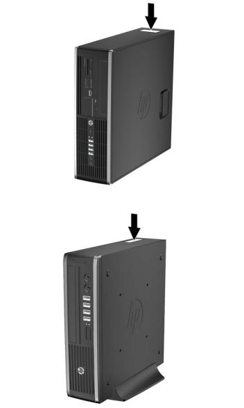
Figure 1-14 Small Form Factor Serial Number and Product ID Location
Figure 1-15 Ultra-Slim Desktop (USDT) Serial Number and Product ID Location
12 Chapter 1 Product Features

2Activating and Customizing the Software
 NOTE: This chapter provides information for both Windows 7 and Windows 8.
Activating and customizing the software in Windows 7
If your computer was not shipped with a Windows® operating system, some portions of this documentation do not apply. Additional information is available in online help after you activate the operating system.
CAUTION: Do not add optional hardware or third-party devices to the computer until the operating system is successfully activated. Doing so may cause errors and prevent the operating system from installing properly.


 NOTE: Be sure there is a 10.2 cm (4 inch) clearance at the back of the unit and above the monitor to permit the required airflow.
Activating the Windows operating system
The first time you turn on the computer, the operating system is set up and activated automatically. This process takes about 5 to 10 minutes. Carefully read and follow the instructions on the screen to complete the activation.
We recommend that you register your computer with HP during operating system setup so you can receive important software updates, facilitate support questions, and sign up for special offers.
CAUTION: After the activation process has begun, DO NOT TURN OFF THE COMPUTER UNTIL THE PROCESS IS COMPLETE. Turning off the computer during the activation process may damage the software that runs the computer or prevent its proper installation.


 NOTE: If the computer shipped with more than one operating system language on the hard drive, the activation process could take up to 60 minutes.
Activating and customizing the software in Windows 7 13

Downloading Windows 7 updates
Microsoft may release updates to the operating system. To help keep the computer running optimally, HP recommends checking for the latest updates during the initial installation and periodically throughout the life of the computer.
1.To set up your Internet connection, click Start > Internet Explorer and follow the instructions on the screen.
2.After an Internet connection has been established, click the Start > All Programs > Windows Update.
3.Run Windows Update monthly thereafter.
Installing or upgrading device drivers
When installing optional hardware devices after the operating system installation is complete, you must also install the drivers for each of the devices.
In Windows 7, if prompted for the i386 directory, replace the path specification with C:\i386, or use the Browse button in the dialog box to locate the i386 folder. This action points the operating system to the appropriate drivers.
Obtain the latest support software, including support software for the operating system, from http://www.hp.com/support. Select your country and language, select Download drivers and software (and firmware), enter the model number of the computer, and press Enter.
Customizing the monitor display
If you wish, you can select or change the monitor refresh rates, screen resolution, color settings, font sizes, and power management settings.
For more information, refer to the online documentation provided with the graphics controller utility or the documentation that came with your monitor.
Right-click on the Windows desktop, then click Personalize to change display settings.
Activating and customizing the software in Windows 8
Additional information is available in online help after you activate the operating system.


 NOTE: Be sure there is a 10.2 cm (4 inch) clearance at the back of the unit and above the monitor to permit the required airflow.
Activating the Windows Operating System
The first time you turn on the computer, the operating system is set up and activated automatically. This process takes about 5 to 10 minutes. Carefully read and follow the instructions on the screen to complete the activation.
We recommend that you register your computer with HP during operating system set up so you can receive important software updates, facilitate support questions, and sign up for special offers. You can also register your computer with HP using the Register with HP app on the Start screen.
14 Chapter 2 Activating and Customizing the Software

CAUTION: After the activation process has begun, DO NOT TURN OFF THE COMPUTER UNTIL THE PROCESS IS COMPLETE. Turning off the computer during the activation process may damage the software that runs the computer or prevent its proper installation.
Downloading Windows 8 updates
Microsoft may release updates to the operating system. To help keep the computer running optimally, HP recommends checking for the latest updates during the initial installation and periodically throughout the life of the computer.
Run Windows Update as soon as possible after you set up your computer.
1.Point to the upper-right or lower-right corner of the Start screen to display the charms.
2.Click Settings > Change PC Settings > Windows Update.
3.Run Windows Update monthly thereafter.
Customizing the monitor display
You can customize display settings for Windows 8 separately for the Start screen and the Desktop.
To customize the Start screen:
1.Point to the upper-right or lower-right corner of the Start screen to display the charms.
2.Click Settings > Change PC Settings.
3.Click Personalize to change the display settings.
To customize the Desktop:
1.Click the Desktop app on the Start screen.
2.Right-click on the desktop, and then click Personalize to change display settings.
Activating and customizing the software in Windows 8 15

3 Computer Setup (F10) Utility
Computer Setup (F10) Utilities
Use Computer Setup (F10) Utility to do the following:
●Change factory default settings.
●Set the system date and time.
●Set, view, change, or verify the system configuration, including settings for processor, graphics, memory, audio, storage, communications, and input devices.
●Modify the boot order of bootable devices such as hard drives, optical drives, or USB flash media devices.
●Enable Quick Boot, which is faster than Full Boot but does not run all of the diagnostic tests run during a Full Boot. You can set the system to:
always Quick Boot (default);
periodically Full Boot (from every 1 to 30 days); or
always Full Boot.
●Select Post Messages Enabled or Disabled to change the display status of Power-On Self-Test (POST) messages. Post Messages Disabled suppresses most POST messages, such as memory count, product name, and other non-error text messages. If a POST error occurs, the error is displayed regardless of the mode selected. To manually switch to Post Messages Enabled during POST, press any key (except F1 through F12).
●Establish an Ownership Tag, the text of which is displayed each time the system is turned on or restarted.
●Enter the Asset Tag or property identification number assigned by the company to this computer.
●Enable the power-on password prompt during system restarts (warm boots) as well as during power-on.
●Establish a setup password that controls access to the Computer Setup (F10) Utility and the settings described in this section.
●Secure integrated I/O functionality, including the serial, USB, or parallel ports, audio, or embedded NIC, so that they cannot be used until they are unsecured.
●Enable or disable removable media boot ability.
16 Chapter 3 Computer Setup (F10) Utility

●Solve system configuration errors detected but not automatically fixed during the Power-On SelfTest (POST).
●Replicate the system setup by saving system configuration information on a USB device and restoring it on one or more computers.
●Execute self-tests on a specified ATA hard drive (when supported by drive).
●Enable or disable DriveLock security (when supported by drive).
Using Computer Setup (F10) Utilities
Computer Setup can be accessed only by turning the computer on or restarting the system. To access the Computer Setup Utilities menu, complete the following steps:
1.Turn on or restart the computer.
2.Repeatedly press F10 when the monitor light turns green to access the utility.
You can also press Esc to a menu that allows you to access different options available at startup, including the Computer Setup utility.


 NOTE: If you do not press F10 at the appropriate time, you must restart the computer and again repeatedly press F10 when the monitor light turns green to access the utility.
3.A choice of five headings appears in the Computer Setup Utilities menu: File, Storage, Security, Power, and Advanced.
4.Use the arrow (left and right) keys to select the appropriate heading. Use the arrow (up and down) keys to select the option you want, then press Enter. To return to the Computer Setup Utilities menu, press Esc.
5.To apply and save changes, select File > Save Changes and Exit.
●If you have made changes that you do not want applied, select Ignore Changes and Exit.
●To reset to factory settings or previously saved default settings (some models), select Apply Defaults and Exit. This option will restore the original factory system defaults.
 NOTE: Not all settings shown in the following sections are available for all models
CAUTION: Do NOT turn the computer power OFF while the BIOS is saving the Computer Setup (F10) changes because the CMOS could become corrupted. It is safe to turn off the computer only after exiting the F10 Setup screen.
Table 3-1 Computer Setup (F10) Utility
Heading |
Table |
|
|
File |
Computer Setup—File on page 18 |
|
|
Storage |
Computer Setup—Storage on page 19 |
|
|
Security |
Computer Setup—Security on page 22 |
|
|
Power |
Computer Setup—Power on page 27 |
|
|
Advanced |
Computer Setup—Advanced on page 28 |
|
|
Computer Setup (F10) Utilities 17

Computer Setup—File


 NOTE: Support for specific Computer Setup options may vary depending on the hardware configuration.
Table 3-2 Computer Setup—File
Option |
Description |
|
|
|
|
System Information |
Lists: |
|
|
● |
Product name |
|
● |
SKU number |
|
● |
Processor type/speed/stepping |
|
● Cache size (L1/L2/L3) (dual core processors have this listed twice) |
|
|
● Installed memory size/speed, number of channels (single or dual) (if applicable) |
|
|
● Integrated MAC address for embedded, enabled NIC (if applicable) |
|
|
● System BIOS (includes family name and version) |
|
|
● |
Chassis serial number |
|
● |
Asset tracking number |
|
● |
ME firmware version |
|
● |
ME Management mode |
|
|
|
About |
Displays copyright notice. |
|
|
|
|
Set Time and Date |
Allows you to set system time and date. |
|
|
|
|
Flash System ROM |
Allows you to update the system ROM with a BIOS image file located on removable media. |
|
|
|
|
Replicated Setup |
Save to Removable Media |
|
|
Saves system configuration to a formatted USB flash media device. |
|
|
Restore from Removable Media |
|
|
Restores system configuration from a USB flash media device. |
|
|
|
|
Default Setup |
Save Current Settings as Default |
|
|
Saves the current system configuration settings as the default. |
|
|
Restore Factory Settings as Default |
|
|
Restores the factory system configuration settings as the default. |
|
|
|
|
Apply Defaults and |
Applies the currently selected default settings and clears any established passwords. |
|
Exit |
|
|
|
|
|
Ignore Changes |
Exits Computer Setup without applying or saving any changes. |
|
and Exit |
|
|
|
|
|
Save Changes and |
Saves changes to system configuration or default settings and exits Computer Setup. |
|
Exit |
|
|
|
|
|
18 Chapter 3 Computer Setup (F10) Utility
Loading...