


 Loading...
HP ProLiant DL360 Generation 5 Server
User Guide
Second Edition (May 2006)
Part Number 406316-002
© Copyright 2006 Hewlett-Packard Development Company, L.P.
The information contained herein is subject to change without notice. The only warranties for HP products and services are set forth in the express warranty statements accompanying such products and services. Nothing herein should be construed as constituting an additional warranty. HP shall not be liable for technical or editorial errors or omissions contained herein.
Microsoft, Windows, and Windows NT are U.S. registered trademarks of Microsoft Corporation. Windows Server 2003 is a trademark of Microsoft Corporation.
Linux is a U.S. registered trademark of Linus Torvalds.
Second Edition (May 2006)
Part Number 406316-002

Contents |
|
Component identification............................................................................................................... |
7 |
Front panel components ............................................................................................................................. |
7 |
Front panel LEDs and buttons ...................................................................................................................... |
8 |
Rear panel components.............................................................................................................................. |
9 |
Rear panel LEDs and buttons..................................................................................................................... |
10 |
System board components........................................................................................................................ |
11 |
System maintenance switch............................................................................................................. |
12 |
NMI switch................................................................................................................................... |
12 |
HP Systems Insight Display and LEDs.......................................................................................................... |
12 |
HP Systems Insight Display LEDs and internal health LED combinations ........................................................... |
13 |
SAS and SATA device numbers................................................................................................................. |
15 |
SAS and SATA hard drive LEDs................................................................................................................. |
16 |
SAS and SATA hard drive LED combinations .............................................................................................. |
16 |
Fan locations .......................................................................................................................................... |
17 |
Operations................................................................................................................................. |
18 |
Power up the server ................................................................................................................................. |
18 |
Power down the server............................................................................................................................. |
18 |
Access the HP Systems Insight Display........................................................................................................ |
18 |
Extend the server from the rack ................................................................................................................. |
19 |
Remove the access panel.......................................................................................................................... |
20 |
Install the access panel............................................................................................................................. |
20 |
Remove the PCI riser board assembly......................................................................................................... |
20 |
Install the PCI riser board assembly............................................................................................................ |
21 |
Remove the power supply air baffle ........................................................................................................... |
21 |
Remove the processor air baffle ................................................................................................................ |
22 |
Remove and install a fan module............................................................................................................... |
22 |
Setup......................................................................................................................................... |
25 |
Optional installation services .................................................................................................................... |
25 |
Rack planning resources........................................................................................................................... |
26 |
Optimum environment.............................................................................................................................. |
26 |
Space and airflow requirements ...................................................................................................... |
26 |
Temperature requirements............................................................................................................... |
27 |
Power requirements ....................................................................................................................... |
27 |
Electrical grounding requirements .................................................................................................... |
27 |
Rack warnings ........................................................................................................................................ |
28 |
Contents of the server shipping carton........................................................................................................ |
28 |
Installing hardware options....................................................................................................................... |
28 |
Installing the server into the rack................................................................................................................ |
28 |
Powering up and configuring the server ..................................................................................................... |
30 |
Installing the operating system................................................................................................................... |
30 |
Registering the server............................................................................................................................... |
31 |
Hardware options installation....................................................................................................... |
32 |
Introduction ............................................................................................................................................ |
32 |
Processor option...................................................................................................................................... |
32 |
Memory options ...................................................................................................................................... |
37 |
Memory configurations................................................................................................................... |
37 |
Advanced ECC memory ................................................................................................................. |
38 |
Online spare memory configuration ................................................................................................. |
38 |
Contents |
3 |
Mirrored memory configuration ....................................................................................................... |
39 |
Installing FBDIMMs ........................................................................................................................ |
40 |
Hot-plug SAS and SATA hard drive options ................................................................................................ |
40 |
Removing hard drive blanks............................................................................................................ |
41 |
Removing hard drive bezel blanks ................................................................................................... |
41 |
Removing a hot-plug SAS or SATA hard drive ................................................................................... |
42 |
Installing a hot-plug SAS or SATA hard drive .................................................................................... |
42 |
Multibay device options ........................................................................................................................... |
43 |
Redundant hot-plug power supply option .................................................................................................... |
44 |
Expansion board options.......................................................................................................................... |
46 |
Installing an expansion board ......................................................................................................... |
46 |
Installing a PCI-X riser board ........................................................................................................... |
47 |
HP Smart Array controller options.............................................................................................................. |
49 |
Removing an integrated HP Smart Array E200i Controller or an HP Smart Array P400i Controller ........... |
50 |
Installing an integrated HP Smart Array E200i Controller or an HP Smart Array P400i Controller ............ |
51 |
Upgrading an HP Smart Array E200i Controller cache module and battery pack................................... |
52 |
Installing an HP Smart Array P400i Controller cache module and battery pack...................................... |
55 |
Upgrading the HP Smart Array P400i Controller to support six hard drives ........................................... |
59 |
Using a PCI SAS or SATA array controller to support six hard drives.................................................... |
60 |
Using a PCI array controller and the HP Smart Array P400i Controller to support six hard drives............. |
62 |
Cabling ..................................................................................................................................... |
63 |
Cabling overview.................................................................................................................................... |
63 |
Array controller cabling ........................................................................................................................... |
63 |
HP Smart Array E200i Controller cabling ......................................................................................... |
64 |
HP Smart Array P400i Controller cabling ......................................................................................... |
64 |
PCI Smart Array controller cabling................................................................................................... |
65 |
Battery pack cabling ...................................................................................................................... |
65 |
Multibay backplane cabling ..................................................................................................................... |
66 |
Configuration and utilities ............................................................................................................ |
67 |
Configuration tools .................................................................................................................................. |
67 |
SmartStart software........................................................................................................................ |
67 |
HP ROM-Based Setup Utility............................................................................................................ |
68 |
Array Configuration Utility .............................................................................................................. |
70 |
Option ROM Configuration for Arrays ............................................................................................. |
70 |
HP ProLiant Essentials Rapid Deployment Pack................................................................................... |
70 |
Re-entering the server serial number and product ID ........................................................................... |
71 |
Management tools................................................................................................................................... |
71 |
Automatic Server Recovery ............................................................................................................. |
71 |
ROMPaq utility.............................................................................................................................. |
71 |
System Online ROM flash component utility ...................................................................................... |
72 |
Integrated Lights-Out 2 technology ................................................................................................... |
72 |
Erase Utility .................................................................................................................................. |
72 |
Management Agents...................................................................................................................... |
73 |
HP Systems Insight Manager ........................................................................................................... |
73 |
Redundant ROM support ................................................................................................................ |
73 |
USB support.................................................................................................................................. |
74 |
Internal USB functionality ................................................................................................................ |
74 |
Diagnostic tools ...................................................................................................................................... |
74 |
Survey Utility................................................................................................................................. |
74 |
Array Diagnostic Utility .................................................................................................................. |
75 |
HP Insight Diagnostics.................................................................................................................... |
75 |
Integrated Management Log ........................................................................................................... |
75 |
Contents |
4 |
Remote support and analysis tools ............................................................................................................. |
75 |
HP Instant Support Enterprise Edition................................................................................................ |
75 |
Web-Based Enterprise Service......................................................................................................... |
76 |
Open Services Event Manager ........................................................................................................ |
76 |
Keeping the system current ....................................................................................................................... |
76 |
Drivers ......................................................................................................................................... |
76 |
Resource Paqs............................................................................................................................... |
77 |
ProLiant Support Packs ................................................................................................................... |
77 |
Operating system version support .................................................................................................... |
77 |
System Online ROM flash component utility ...................................................................................... |
77 |
Change control and proactive notification ........................................................................................ |
77 |
Natural language search assistant ................................................................................................... |
77 |
Care Pack .................................................................................................................................... |
78 |
Troubleshooting .......................................................................................................................... |
79 |
Troubleshooting resources ........................................................................................................................ |
79 |
Pre-diagnostic steps ................................................................................................................................. |
79 |
Important safety information............................................................................................................ |
79 |
Symptom information ..................................................................................................................... |
81 |
Prepare the server for diagnosis ...................................................................................................... |
82 |
Loose connections ................................................................................................................................... |
82 |
Service notifications................................................................................................................................. |
82 |
Troubleshooting flowcharts ....................................................................................................................... |
83 |
Start diagnosis flowchart ................................................................................................................ |
83 |
General diagnosis flowchart ........................................................................................................... |
84 |
Server power-on problems flowchart ................................................................................................ |
86 |
POST problems flowchart ............................................................................................................... |
89 |
OS boot problems flowchart ........................................................................................................... |
90 |
Server fault indications flowchart ..................................................................................................... |
92 |
POST error messages and beep codes ....................................................................................................... |
94 |
System battery ............................................................................................................................ |
95 |
Regulatory compliance notices ..................................................................................................... |
96 |
Regulatory compliance identification numbers ............................................................................................. |
96 |
Federal Communications Commission notice............................................................................................... |
96 |
FCC rating label............................................................................................................................ |
96 |
Class A equipment......................................................................................................................... |
97 |
Class B equipment ......................................................................................................................... |
97 |
Declaration of conformity for products marked with the FCC logo, United States only....................................... |
97 |
Modifications.......................................................................................................................................... |
98 |
Cables................................................................................................................................................... |
98 |
Canadian notice (Avis Canadien).............................................................................................................. |
98 |
European Union regulatory notice ............................................................................................................. |
98 |
Disposal of waste equipment by users in private households in the European Union ......................................... |
99 |
Japanese notice ...................................................................................................................................... |
99 |
BSMI notice ............................................................................................................................................ |
99 |
Korean notice ....................................................................................................................................... |
100 |
Laser compliance .................................................................................................................................. |
100 |
Battery replacement notice...................................................................................................................... |
100 |
Taiwan battery recycling notice............................................................................................................... |
101 |
Power cord statement for Japan............................................................................................................... |
101 |
Electrostatic discharge............................................................................................................... |
102 |
Preventing electrostatic discharge ............................................................................................................ |
102 |
|
Contents 5 |
Grounding methods to prevent electrostatic discharge |
................................................................................ 102 |
Specifications........................................................................................................................... |
103 |
Environmental specifications ................................................................................................................... |
103 |
Server specifications .............................................................................................................................. |
103 |
Technical support...................................................................................................................... |
105 |
Related documents ................................................................................................................................ |
105 |
HP contact information........................................................................................................................... |
105 |
Customer Self Repair ............................................................................................................................. |
105 |
Acronyms and abbreviations...................................................................................................... |
113 |
Index....................................................................................................................................... |
116 |
Contents 6

Component identification
In this section |
|
Front panel components ............................................................................................................................ |
7 |
Front panel LEDs and buttons ..................................................................................................................... |
8 |
Rear panel components............................................................................................................................. |
9 |
Rear panel LEDs and buttons ................................................................................................................... |
10 |
System board components....................................................................................................................... |
11 |
HP Systems Insight Display and LEDs ........................................................................................................ |
12 |
HP Systems Insight Display LEDs and internal health LED combinations ......................................................... |
13 |
SAS and SATA device numbers ............................................................................................................... |
15 |
SAS and SATA hard drive LEDs ............................................................................................................... |
16 |
SAS and SATA hard drive LED combinations............................................................................................. |
16 |
Fan locations ......................................................................................................................................... |
17 |
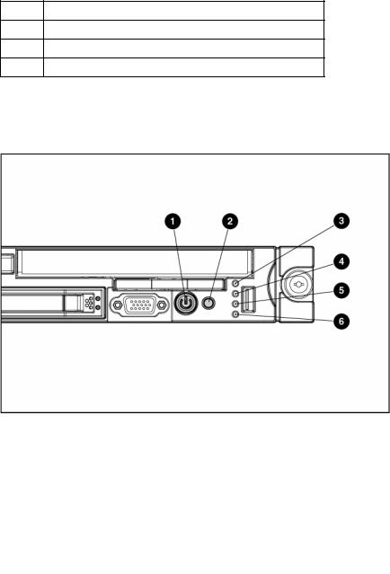
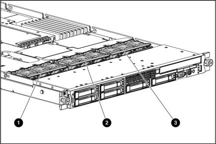
Front panel components
Item |
Description |
|
|
1 |
Hard drive bay 5 (optional)* |
|
|
2 |
Hard drive bay 6 (optional)* |
|
|
3 |
Multibay drive bay |
|
|
4 |
USB connector |
|
|
5 |
HP Systems Insight Display |
|
|
6 |
Video connector |
|
|
7 |
Hard drive bay 4 |
|
|
Component identification 7
Item Description
8Hard drive bay 3
9Hard drive bay 2
10Hard drive bay 1
*An optional controller is required when the server is configured with six hard drives.
Front panel LEDs and buttons
Item |
Description |
Status |
|
|
|
1 |
Power On/Standby button |
Green = System is on. |
|
and system power LED |
Amber = System is shut down, but power is still applied. |
|
|
|
|
|
Off = Power cord is not attached, power supply failure has |
|
|
occurred, no power supplies are installed, facility power is not |
|
|
available, or disconnected power button cable. |
|
|
|
2 |
UID button/LED |
Blue = Identification is activated. |
|
|
Flashing blue = System is being remotely managed. |
|
|
Off = Identification is deactivated. |
|
|
|
3 |
Internal health LED |
Green = System health is normal. |
|
|
Amber = System health is degraded. To identify the component in |
|
|
a degraded state, refer to "HP Systems Insight Display and LEDs" |
|
|
("HP Systems Insight Display and LEDs" on page 12). |
|
|
Red = System health is critical. To identify the component in a |
|
|
critical state, refer to "HP Systems Insight Display and LEDs" ("HP |
|
|
Systems Insight Display and LEDs" on page 12). |
|
|
Off = System health is normal (when in standby mode). |
|
|
|
4 |
External health LED |
Green = Power supply health is normal. |
|
(power supply) |
Amber = Power redundancy failure occurred. |
|
|
|
|
|
Off = Power supply health is normal when in standby mode. |
|
|
|
Component identification 8

Item |
Description |
Status |
|
|
|
5 |
NIC 1 link/activity LED |
Green = Network link exists. |
|
|
Flashing green = Network link and activity exist. |
|
|
Off = No link to network exists. |
|
|
If power is off, the front panel LED is not active. View the LEDs on |
|
|
the RJ-45 connector for status by referring to the rear panel LEDs |
|
|
("Rear panel LEDs and buttons" on page 10). |
|
|
|
6 |
NIC 2 link/activity LED |
Green = Network link exists. |
|
|
Flashing green = Network link and activity exist. |
|
|
Off = No link to network exists. |
|
|
If power is off, the front panel LED is not active. View the LEDs on |
|
|
the RJ-45 connector for status by referring to the rear panel LEDs |
|
|
("Rear panel LEDs and buttons" on page 10). |
|
|
|
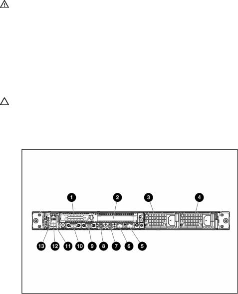
Rear panel components
Item |
Description |
|
|
1 |
PCI Express expansion slot 1, low-profile, half-length |
|
|
2 |
PCI Express expansion slot 2 |
|
|
3 |
Power supply bay 2 |
|
|
4 |
Power supply bay 1 |
|
|
5 |
NIC 2 connector |
|
|
6 |
NIC 1 connector |
|
|
7 |
Keyboard connector |
|
|
8 |
Mouse connector |
|
|
9 |
Video connector |
|
|
10 |
Serial connector |
|
|
11 |
USB connector |
|
|
12 |
USB connector |
|
|
Component identification 9
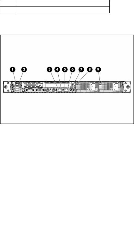
Item Description
13 iLO 2 NIC connector
Rear panel LEDs and buttons
Item |
Description |
Status |
|
|
|
1 |
iLO 2 NIC activity |
Green = Activity exists. |
|
LED |
Flashing green = Activity exists. |
|
|
|
|
|
Off = No activity exists. |
|
|
|
2 |
iLO 2 NIC link |
Green = Link exists. |
|
LED |
Off = No link exists. |
|
|
|
|
|
|
3 |
10/100/1000 |
Green = Activity exists. |
|
NIC 1 activity LED |
Flashing green = Activity exists. |
|
|
Off = No activity exists. |
|
|
|
4 |
10/100/1000 |
Green = Link exists. |
|
NIC 1 link LED |
Off = No link exists. |
|
|
|
5 |
10/100/1000 |
Green = Activity exists. |
|
NIC 2 activity LED |
Flashing green = Activity exists. |
|
|
Off = No activity exists. |
|
|
|
6 |
10/100/1000 |
Green = Link exists. |
|
NIC 2 link LED |
Off = No link exists. |
|
|
|
7 |
UID button/LED |
Blue = Identification is activated. |
|
|
Flashing blue = System is being managed |
|
|
remotely. |
|
|
Off = Identification is deactivated. |
|
|
|
8 |
Power supply 2 |
Green = Normal |
|
LED |
Off = System is off or power supply has failed |
|
|
|
|
|
|
9 |
Power supply 1 |
Green = Normal |
|
LED |
Off = System is off or power supply has failed |
|
|
|
|
|
|
Component identification 10
System board components
Item |
Description |
|
|
1 |
System maintenance switch (SW1) |
|
|
2 |
NMI switch |
|
|
3 |
FBDIMM slots (1-8) |
|
|
4 |
Processor socket 2 |
|
|
5 |
Processor socket 1 |
|
|
6 |
Multibay drive connector |
|
|
7 |
Power button connector |
|
|
8 |
Fan module 3 connectors |
|
|
9 |
Fan module 2 connectors |
|
|
10 |
Fan module 1 connectors |
|
|
11 |
SAS hard drive backplane power connector |
|
|
12 |
Integrated Smart Array controller connector |
|
|
13 |
Power supply connector 1 |
|
|
14 |
Power supply connector 2 |
|
|
15 |
Internal USB connector |
|
|
16 |
System battery |
|
|
17 |
PCI riser board connector 2 |
|
|
18 |
PCI riser board connector 1 |
|
|
Component identification 11

System maintenance switch
Position |
Default |
Function |
|
|
|
S1 |
Off |
Off = iLO 2 security is enabled. |
|
|
On = iLO 2 security is disabled. |
|
|
|
S2 |
Off |
Off = System configuration can be modified. |
|
|
On = System configuration is locked and cannot be modified. |
|
|
|
S3 |
Off |
Reserved |
|
|
|
S4 |
Off |
Reserved |
|
|
|
S5 |
Off |
Off = Power-on password is enabled. |
|
|
On = Power-on password is disabled. |
|
|
|
S6 |
Off |
Off = Normal |
|
|
On = ROM treats system configuration as invalid. |
|
|
|
S7 |
Off |
Reserved |
|
|
|
S8 |
Off |
Reserved |
|
|
|
When the system maintenance switch position 6 is set to the On position, the system is prepared to erase all system configuration settings from both CMOS and NVRAM.
CAUTION: Clearing CMOS and/or NVRAM deletes configuration information. Be sure to properly configure the server or data loss could occur.
NMI switch
The NMI switch allows administrators to perform a memory dump before performing a hard reset. Crash dump analysis is an essential part of eliminating reliability problems, such as hangs or crashes in operating systems, device drivers, and applications. Many crashes freeze a system, requiring you to do a hard reset. Resetting the system erases any information that would support root cause analysis.
Systems running Microsoft® Windows® operating systems experience a blue screen trap when the operating system crashes. When this happens, Microsoft® recommends that system administrators perform an NMI event by pressing a dump switch. The NMI event enables a hung system to become responsive again.
HP Systems Insight Display and LEDs
The display provides status for all internal LEDs and enables diagnosis with the access panel installed.
Component identification 12
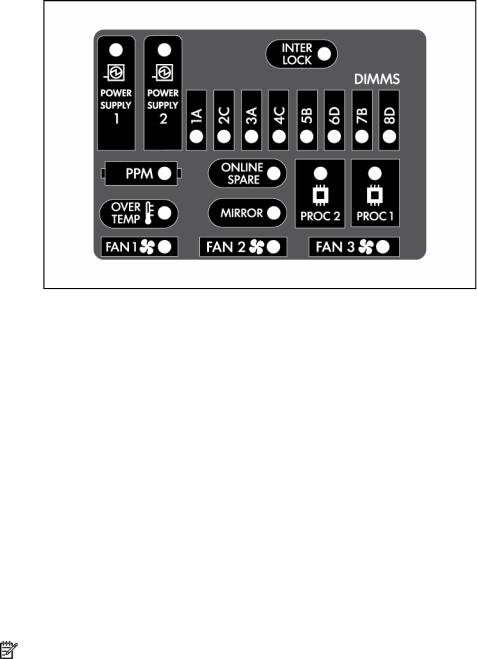
To view the LEDs, access the HP Systems Insight Display (on page 18).
Item |
Description |
Status |
|
|
|
1 |
Online spare memory |
Green = Protection enabled |
|
LED |
Flashing amber = Memory configuration |
|
|
|
|
|
error |
|
|
Amber = Memory failure occurred |
|
|
Off = No protection |
|
|
|
2 |
Mirrored memory LED |
Green = Protection enabled |
|
|
Flashing amber = Memory configuration |
|
|
error |
|
|
Amber = Memory failure occurred |
|
|
Off = No protection |
|
|
|
|
All other LEDs |
Amber = Failure |
|
|
Off = Normal |
|
|
For additional information detailing the |
|
|
causes for the activation of these LEDs, |
|
|
refer to HP Systems Insight Display LEDs |
|
|
and internal health LED combinations (on |
|
|
page 13). |
|
|
|
NOTE: The HP Systems Insight Display LEDs represent the system board layout.
HP Systems Insight Display LEDs and internal health LED combinations
When the internal health LED on the front panel illuminates either amber or red, the server is experiencing a health event. Combinations of illuminated system LEDs and the internal health LED indicate system status.
The front panel health LEDs indicate only the current hardware status. In some situations, HP SIM may report server status differently than the health LEDs because the software tracks more system attributes.
Component identification 13
HP Systems Insight |
Internal health LED |
Status |
Display LED and color |
color |
|
|
|
|
Processor failure, socket X |
Red |
One or more of the following conditions may exist: |
(amber) |
|
• Processor in socket X has failed. |
|
|
|
|
|
• Processor X is required yet not installed in the socket. |
|
|
• Processor X is unsupported. |
|
|
|
|
Amber |
Processor in socket X is in a pre-failure condition. |
|
|
|
Processor failure, both |
Red |
Processor types are mismatched. |
sockets (amber) |
|
|
PPM failure (amber) |
Red |
Integrated PPM has failed. |
|
|
|
FBDIMM failure, slot X |
Red |
One or more of the following conditions may exist: |
(amber) |
|
• FBDIMM in slot X has failed. |
|
|
|
|
|
• FBDIMM in slot X is an unsupported type, and no |
|
|
valid memory exists in another bank. |
|
|
|
|
Amber |
One or more of the following conditions may exist: |
|
|
• FBDIMM in slot X has reached single-bit correctable |
|
|
error threshold. |
|
|
• FBDIMM in slot X is in a pre-failure condition. |
|
|
• FBDIMM in slot X is an unsupported type, but valid |
|
|
memory exists in another bank. |
FBDIMM failure, all slots |
Red |
No valid or usable memory is installed in the system. |
(amber) |
|
|
|
|
|
Overtemperature (amber) |
Amber |
The health driver has detected a cautionary temperature |
|
|
level. |
|
|
|
|
Red |
The server has detected a critical temperature level. |
|
|
|
Riser interlock (amber) |
Red |
The PCI riser board assembly is not seated properly. |
|
|
|
Online spare memory |
Amber |
Bank X failed over to the online spare memory bank. |
(amber) |
|
|
|
|
|
Fan module (amber) |
Amber |
A redundant fan has failed. |
|
|
|
Fan module (amber) |
Red |
The minimum fan requirements are not being met in one |
|
|
or more of the fan modules. One or more fans have failed |
|
|
or are missing. |
|
|
|
Component identification 14

SAS and SATA device numbers
•Four hard drive configuration
•Six hard drive configuration
Component identification 15
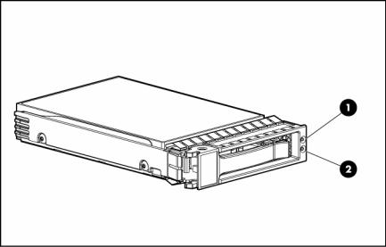
SAS and SATA hard drive LEDs
Item |
Description |
|
|
1 |
Fault/UID LED (amber/blue) |
|
|
2 |
Online LED (green) |
|
|
SAS and SATA hard drive LED combinations
Online/activity LED |
Fault/UID LED |
Interpretation |
(green) |
(amber/blue) |
|
|
|
|
On, off, or flashing |
Alternating amber |
The drive has failed, or a predictive failure alert has been |
|
and blue |
received for this drive; it also has been selected by a |
|
|
management application. |
On, off, or flashing |
Steadily blue |
The drive is operating normally, and it has been selected by a |
|
|
management application. |
|
|
|
On |
Amber, flashing |
A predictive failure alert has been received for this drive. |
|
regularly (1 Hz) |
Replace the drive as soon as possible. |
|
|
|
|
|
|
On |
Off |
The drive is online, but it is not active currently. |
|
|
|
Flashing regularly |
Amber, flashing |
Do not remove the drive. Removing a drive may |
(1 Hz) |
regularly (1 Hz) |
terminate the current operation and cause data loss. |
|
|
The drive is part of an array that is undergoing capacity |
|
|
expansion or stripe migration, but a predictive failure alert has |
|
|
been received for this drive. To minimize the risk of data loss, do |
|
|
not replace the drive until the expansion or migration is |
|
|
complete. |
Flashing regularly |
Off |
Do not remove the drive. Removing a drive may |
(1 Hz) |
|
terminate the current operation and cause data loss. |
|
|
The drive is rebuilding, or it is part of an array that is undergoing |
|
|
capacity expansion or stripe migration. |
|
|
|
Flashing irregularly |
Amber, flashing |
The drive is active, but a predictive failure alert has been |
|
regularly (1 Hz) |
received for this drive. Replace the drive as soon as possible. |
Flashing irregularly |
Off |
The drive is active, and it is operating normally. |
|
|
|
Component identification 16
Online/activity LED |
Fault/UID LED |
Interpretation |
(green) |
(amber/blue) |
|
|
|
|
Off |
Steadily amber |
A critical fault condition has been identified for this drive, and |
|
|
the controller has placed it offline. Replace the drive as soon as |
|
|
possible. |
Off |
Amber, flashing |
A predictive failure alert has been received for this drive. |
|
regularly (1 Hz) |
Replace the drive as soon as possible. |
|
|
|
Off |
Off |
The drive is offline, a spare, or not configured as part of an |
|
|
array. |
|
|
|
Fan locations
Item |
Description |
|
|
1 |
Fan module 1 |
|
|
2 |
Fan module 2 |
|
|
3 |
Fan module 3 |
|
|
Component identification 17

Operations
In this section |
|
Power up the server ................................................................................................................................ |
18 |
Power down the server............................................................................................................................ |
18 |
Access the HP Systems Insight Display ...................................................................................................... |
18 |
Extend the server from the rack ................................................................................................................ |
19 |
Remove the access panel ........................................................................................................................ |
20 |
Install the access panel ........................................................................................................................... |
20 |
Remove the PCI riser board assembly ....................................................................................................... |
20 |
Install the PCI riser board assembly .......................................................................................................... |
21 |
Remove the power supply air baffle.......................................................................................................... |
21 |
Remove the processor air baffle ............................................................................................................... |
22 |
Remove and install a fan module.............................................................................................................. |
22 |
Power up the server |
|
To power up the server, press the Power On/Standby button. |
|
Power down the server |
|
WARNING: To reduce the risk of personal injury, electric shock, or damage to the equipment, remove the power cord to remove power from the server. The front panel Power On/Standby button does not completely shut off system power. Portions of the power supply and some internal circuitry remain active until AC power is removed.
IMPORTANT: If installing a hot-plug device, it is not necessary to power down the server.
1.Back up the server data.
2.Shut down the operating system as directed by the operating system documentation.
3.If the server is installed in a rack, press the UID LED button on the front panel. Blue LEDs illuminate on the front and rear panels of the server.
4.Press the Power On/Standby button to place the server in standby mode. When the server activates standby power mode, the system power LED changes to amber.
5.If the server is installed in a rack, locate the server by identifying the illuminated rear UID LED button.
6.Disconnect the power cords.
The system is now without power.
Access the HP Systems Insight Display
To eject the HP Systems Insight Display:
1.Press and release the display.
Operations 18
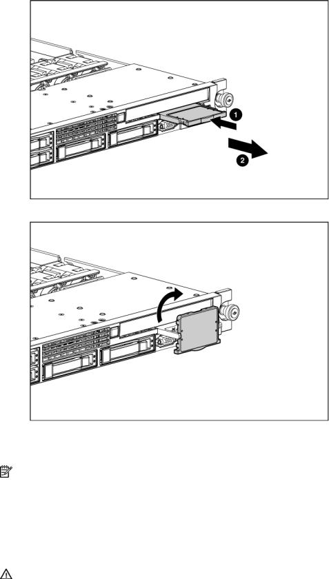
2.Extend the display from the chassis.
The display can be rotated up to 90 degrees.
Extend the server from the rack
NOTE: If the optional cable management arm option is installed, you can extend the server without powering down the server or disconnecting peripheral cables and power cords. These steps are only necessary with the standard cable management solution.
1.Power down the server (on page 18).
2.Disconnect all peripheral cables and power cords.
3.Loosen the front panel thumbscrews.
4.Extend the server on the rack rails until the server rail-release latches engage.
WARNING: To reduce the risk of personal injury or equipment damage, be sure that the rack is adequately stabilized before extending a component from the rack.
Operations 19

WARNING: To reduce the risk of personal injury, be careful when pressing the server rail-release latches and sliding the server into the rack. The sliding rails could pinch your fingers.
5.After performing the installation or maintenance procedure, slide the server into the rack:
a.Slide the server fully into the rack.
b.Secure the server by tightening the thumbscrews.
6.Connect the peripheral cables and power cords.
Remove the access panel
WARNING: To reduce the risk of personal injury from hot surfaces, allow the drives and the internal system components to cool before touching them.
CAUTION: Do not operate the server for long periods with the access panel open or removed. Operating the server in this manner results in improper airflow and improper cooling that can lead to thermal damage.
1.Power down the server if the standard cable management solution is installed ("Power down the server" on page 18).
NOTE: If the optional cable management arm is installed, you can extend the server and perform hot-plug installation or maintenance procedures without powering down the server.
2.Extend or remove the server from the rack ("Extend the server from the rack" on page 19).
3.Lift up on the hood latch handle and remove the access panel.
Install the access panel
1.Place the access panel on top of the server with the hood latch open. Allow the panel to extend past the rear of the server approximately 0.8 cm (0.2 in).
2.Engage the anchoring pin with the corresponding hole in the latch.
3.Push down on the hood latch. The access panel slides to a closed position.
Remove the PCI riser board assembly
CAUTION: To prevent damage to the server or expansion boards, power down the server and remove all AC power cords before removing or installing the PCI riser board assembly.
1.Power down the server (on page 18).
2.Extend or remove the server from the rack ("Extend the server from the rack" on page 19).
3.Remove the access panel (on page 20).
4.Remove the PCI riser board assembly:
a.Disconnect external cables connected to any existing expansion boards.
b.Loosen the four PCI riser board assembly thumbscrews.
Operations 20
c. Lift the assembly to unseat the PCI riser boards and remove the assembly.
Install the PCI riser board assembly
CAUTION: To prevent damage to the server or expansion boards, power down the server and remove all AC power cords before removing or installing the PCI riser board assembly.
1.Align the PCI riser boards with the corresponding connectors on the system board and install the assembly.
2.Tighten the four PCI riser board assembly thumbscrews.
Remove the power supply air baffle
1.Power down the server (on page 18).
2.Extend or remove the server from the rack ("Extend the server from the rack" on page 19).
3.Remove the access panel (on page 20).
Operations 21
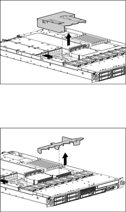
4.Remove the air baffle.
Remove the processor air baffle
1.Power down the server (on page 18).
2.Extend or remove the server from the rack ("Extend the server from the rack" on page 19).
3.Remove the access panel (on page 20).
4.Remove the air baffle.
Remove and install a fan module
The server has three fan modules ("Fan locations" on page 17).
To remove a fan module:
1.Power down the server (on page 18).
Operations 22

2.Extend or remove the server from the rack ("Extend the server from the rack" on page 19).
3.Remove the access panel (on page 20).
4.To remove fan module 1:
a.Remove the power supply air baffle (on page 21).
b.Remove fan module 1.
5.To remove fan module 2 or 3:
a.Remove the processor air baffle (on page 22).
b.Remove fan module 2 or 3.
To install a fan module, reverse the removal procedures.
Operations 23
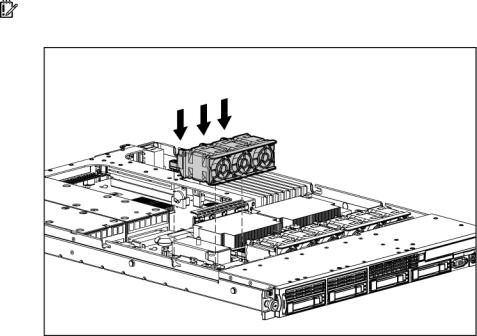
IMPORTANT: After installing the fan module, firmly press the top of the module connectors to ensure the connectors are seated properly.
Operations 24

Setup
In this section |
|
Optional installation services ................................................................................................................... |
25 |
Rack planning resources ......................................................................................................................... |
26 |
Optimum environment............................................................................................................................. |
26 |
Rack warnings ....................................................................................................................................... |
28 |
Contents of the server shipping carton ...................................................................................................... |
28 |
Installing hardware options ..................................................................................................................... |
28 |
Installing the server into the rack .............................................................................................................. |
28 |
Powering up and configuring the server .................................................................................................... |
30 |
Installing the operating system ................................................................................................................. |
30 |
Registering the server.............................................................................................................................. |
31 |
Optional installation services
Delivered by experienced, certified engineers, HP Care Pack services help you keep your servers up and running with support packages tailored specifically for HP ProLiant systems. HP Care Packs let you integrate both hardware and software support into a single package. A number of service level options are available to meet your needs.
HP Care Pack Services offer upgraded service levels to expand your standard product warranty with easy- to-buy, easy-to-use support packages that help you make the most of your server investments. Some of the Care Pack services are:
•Hardware support
•6-Hour Call-to-Repair
•4-Hour 24x7 Same Day
•4-Hour Same Business Day
•Software support
•Microsoft®
•Linux
•HP ProLiant Essentials (HP SIM and RDP)
•VMWare
•Integrated hardware and software support
•Critical Service
•Proactive 24
•Support Plus
•Support Plus 24
•Startup and implementation services for both hardware and software
For more information on Care Packs, refer to the HP website (http://www.hp.com/hps/carepack/servers/cp_proliant.html).
Setup 25

Rack planning resources
The rack resource kit ships with all HP branded or Compaq branded 9000, 10000, and H9 series racks. For more information on the content of each resource, refer to the rack resource kit documentation.
If you intend to deploy and configure multiple servers in a single rack, refer to the white paper on highdensity deployment at the HP website (http://www.hp.com/products/servers/platforms).
Optimum environment
When installing the server in a rack, select a location that meets the environmental standards described in this section.
Space and airflow requirements
To allow for servicing and adequate airflow, observe the following space and airflow requirements when deciding where to install a rack:
•Leave a minimum clearance of 63.5 cm (25 in) in front of the rack.
•Leave a minimum clearance of 76.2 cm (30 in) behind the rack.
•Leave a minimum clearance of 121.9 cm (48 in) from the back of the rack to the back of another rack or row of racks.
HP servers draw in cool air through the front door and expel warm air through the rear door. Therefore, the front and rear rack doors must be adequately ventilated to allow ambient room air to enter the cabinet, and the rear door must be adequately ventilated to allow the warm air to escape from the cabinet.
CAUTION: To prevent improper cooling and damage to the equipment, do not block the ventilation openings.
When vertical space in the rack is not filled by a server or rack component, the gaps between the components cause changes in airflow through the rack and across the servers. Cover all gaps with blanking panels to maintain proper airflow.
CAUTION: Always use blanking panels to fill empty vertical spaces in the rack. This arrangement ensures proper airflow. Using a rack without blanking panels results in improper cooling that can lead to thermal damage.
The 9000 and 10000 Series Racks provide proper server cooling from flow-through perforations in the front and rear doors that provide 64 percent open area for ventilation.
CAUTION: When using a Compaq branded 7000 Series rack, you must install the high airflow rack door insert [P/N 327281-B21 (42U) or P/N 157847-B21 (22U)] to provide proper front-to-back airflow and cooling.
CAUTION: If a third-party rack is used, observe the following additional requirements to ensure adequate airflow and to prevent damage to the equipment:
•Front and rear doors—If the 42U rack includes closing front and rear doors, you must allow 5,350 sq cm (830 sq in) of holes evenly distributed from top to bottom to permit adequate airflow (equivalent to the required 64 percent open area for ventilation).
•Side—The clearance between the installed rack component and the side panels of the rack must be a minimum of 7 cm (2.75 in).
Setup 26

Temperature requirements
To ensure continued safe and reliable equipment operation, install or position the system in a wellventilated, climate-controlled environment.
The maximum recommended ambient operating temperature (TMRA) for most server products is 35°C (95°F). The temperature in the room where the rack is located must not exceed 35°C (95°F).
CAUTION: To reduce the risk of damage to the equipment when installing third-party options:
•Do not permit optional equipment to impede airflow around the server or to increase the internal rack temperature beyond the maximum allowable limits.
•Do not exceed the manufacturer’s TMRA.
Power requirements
Installation of this equipment must comply with local and regional electrical regulations governing the installation of information technology equipment by licensed electricians. This equipment is designed to operate in installations covered by NFPA 70, 1999 Edition (National Electric Code) and NFPA-75, 1992 (code for Protection of Electronic Computer/Data Processing Equipment). For electrical power ratings on options, refer to the product rating label or the user documentation supplied with that option.
WARNING: To reduce the risk of personal injury, fire, or damage to the equipment, do not overload the AC supply branch circuit that provides power to the rack. Consult the electrical authority having jurisdiction over wiring and installation requirements of your facility.
CAUTION: Protect the server from power fluctuations and temporary interruptions with a regulating uninterruptible power supply (UPS). This device protects the hardware from damage caused by power surges and voltage spikes and keeps the system in operation during a power failure.
When installing more than one server, you may need to use additional power distribution devices to safely provide power to all devices. Observe the following guidelines:
•Balance the server power load between available AC supply branch circuits.
•Do not allow the overall system AC current load to exceed 80 percent of the branch circuit AC current rating.
•Do not use common power outlet strips for this equipment.
•Provide a separate electrical circuit for the server.
For more information on the hot-plug power supply and calculators to determine server power consumption in various system configurations, refer to the HP Enterprise Configurator website (http://h30099.www3.hp.com/configurator/).
Electrical grounding requirements
The server must be grounded properly for proper operation and safety. In the United States, you must install the equipment in accordance with NFPA 70, 1999 Edition (National Electric Code), Article 250, as well as any local and regional building codes. In Canada, you must install the equipment in accordance with Canadian Standards Association, CSA C22.1, Canadian Electrical Code. In all other countries, you must install the equipment in accordance with any regional or national electrical wiring codes, such as the International Electrotechnical Commission (IEC) Code 364, parts 1 through 7. Furthermore, you must be sure that all power distribution devices used in the installation, such as branch wiring and receptacles, are listed or certified grounding-type devices.
Because of the high ground-leakage currents associated with multiple servers connected to the same power source, HP recommends the use of a PDU that is either permanently wired to the building’s branch circuit or includes a nondetachable cord that is wired to an industrial-style plug. NEMA locking-style plugs
Setup 27

or those complying with IEC 60309 are considered suitable for this purpose. Using common power outlet strips for the server is not recommended.
Rack warnings
WARNING: To reduce the risk of personal injury or damage to the equipment, be sure that:
•The leveling jacks are extended to the floor.
•The full weight of the rack rests on the leveling jacks.
•The stabilizing feet are attached to the rack if it is a single-rack installation.
•The racks are coupled together in multiple-rack installations.
•Only one component is extended at a time. A rack may become unstable if more than one component is extended for any reason.
WARNING: To reduce the risk of personal injury or equipment damage when unloading a rack:
•At least two people are needed to safely unload the rack from the pallet. An empty 42U rack can weigh as much as 115 kg (253 lb), can stand more than 2.1 m (7 ft) tall, and may become unstable when being moved on its casters.
•Never stand in front of the rack when it is rolling down the ramp from the pallet. Always handle the rack from both sides.
Contents of the server shipping carton
Unpack the server shipping carton and locate the materials and documentation necessary for installing the server. All the rack mounting hardware necessary for installing the server into the rack is included with the rack or the server.
The contents of the server shipping carton include:
•Server
•Power cord
•Printed setup documentation, Documentation CD, and software products
•Rack mounting hardware kit and documentation
In addition to these supplied items, you may need:
•T-15 Torx screwdriver
•Hardware options
•Operating system or application software
Installing hardware options
Install any hardware options before initializing the server. For options installation information, refer to the option documentation. For server-specific information, refer to "Hardware options installation (on page 32)."
Installing the server into the rack
To install the server into a rack with square, round, or threaded holes, refer to the instructions that ship with the rack hardware kit.
Setup 28
If you are installing the server into a telco rack, order the appropriate option kit at the RackSolutions.com website (http://www.racksolutions.com/hp). Follow the server-specific instructions on the website to install the rack brackets.
Use the following information when connecting peripheral cables and power cords to the server.
WARNING: This server is very heavy. To reduce the risk of personal injury or damage to the equipment:
•Observe local occupational health and safety requirements and guidelines for manual material handling.
•Get help to lift and stabilize the product during installation or removal, especially when the product is not fastened to the rails. When the server weighs more than 22.5 kg (50 lb), at least two people must lift the server into the rack together. A third person may be required to help align the server if the server is installed higher than chest level.
•Use caution when installing the server in or removing the server from the rack; it is unstable when not fastened to the rails.
CAUTION: Always plan the rack installation so that the heaviest item is on the bottom of the rack. Install the heaviest item first, and continue to populate the rack from the bottom to the top.
1.Install the server and cable management arm into the rack. Refer to the installation instructions that ship with the HP 1U Quick Deploy Rail System.
2.Connect the peripheral devices to the server.
Item |
Description |
|
|
1 |
PCI Express expansion slot 1, low-profile, half-length |
|
|
2 |
PCI Express expansion slot 2 |
|
|
3 |
Power supply bay 2 |
|
|
4 |
Power supply bay 1 |
|
|
5 |
NIC 2 connector |
|
|
6 |
NIC 1 connector |
|
|
7 |
Keyboard connector |
|
|
8 |
Mouse connector |
|
|
9 |
Video connector |
|
|
Setup 29
Item Description
10Serial connector
11USB connector
12USB connector
13iLO 2 NIC connector
3.Use the strain relief clip from the server hardware kit to secure the power cord.
Powering up and configuring the server
To power up the server, press the Power On/Standby button.
While the server boots, RBSU and the ORCA utility are automatically configured to prepare the server for operating system installation.
To configure these utilities manually:
•Press the F8 key when prompted during the array controller initialization to configure the array controller using ORCA.
•Press the F9 key when prompted during the boot process to change the server settings using RBSU. The system is set up by default for the English language.
For more information on the automatic configuration, refer to the HP ROM-Based Setup Utility User Guide located on the Documentation CD.
Installing the operating system
To operate properly, the server must have a supported operating system. For the latest information on supported operating systems, refer to the HP website (http://www.hp.com/go/supportos).
Two methods are available to install an operating system on the server:
•SmartStart assisted installation—Insert the SmartStart CD into the CD-ROM drive and reboot the server.
Setup 30
Loading...