


 Loading...
HP ProLiant ML110 G7 Server
User Guide
Abstract
This document is for the person who installs, administers, and troubleshoots servers and storage systems. This document is intended for experienced IT professionals or end-users with no or prior hardware setup experience. HP assumes you are qualified in the servicing of computer equipment and trained in recognizing hazards in products with hazardous energy levels.
Part Number: 638029-003
January 2013
Edition: 3
© Copyright 2011, 2013 Hewlett-Packard Development Company, L.P.
The information contained herein is subject to change without notice. The only warranties for HP products and services are set forth in the express warranty statements accompanying such products and services. Nothing herein should be construed as constituting an additional warranty. HP shall not be liable for technical or editorial errors or omissions contained herein.
Microsoft®, and Windows® are U.S. registered trademarks of Microsoft Corporation.

Contents |
|
Component identification............................................................................................................... |
7 |
Front panel components ............................................................................................................................. |
7 |
Front panel LEDs and buttons ............................................................................................................ |
7 |
Rear panel components.............................................................................................................................. |
8 |
Rear panel LEDs and buttons............................................................................................................. |
9 |
System board components........................................................................................................................ |
10 |
DIMM slot locations ....................................................................................................................... |
11 |
System maintenance switch............................................................................................................. |
11 |
System board LEDs ........................................................................................................................ |
12 |
NMI functionality........................................................................................................................... |
12 |
SAS and SATA drive numbering................................................................................................................ |
13 |
SAS and SATA drive LEDs ........................................................................................................................ |
14 |
SAS and SATA drive LED combinations...................................................................................................... |
14 |
BBWC module LEDs ................................................................................................................................ |
15 |
FBWC module LEDs................................................................................................................................. |
17 |
Fan locations .......................................................................................................................................... |
18 |
Operations................................................................................................................................. |
19 |
Power up the server ................................................................................................................................. |
19 |
Power down the server............................................................................................................................. |
19 |
Unlock and open the tower bezel .............................................................................................................. |
20 |
Remove the tower bezel ........................................................................................................................... |
20 |
Install the tower bezel .............................................................................................................................. |
20 |
Remove the access panel.......................................................................................................................... |
21 |
Install the access panel............................................................................................................................. |
21 |
Remove the air baffle............................................................................................................................... |
22 |
Install the air baffle .................................................................................................................................. |
22 |
Setup......................................................................................................................................... |
24 |
Optional installation services .................................................................................................................... |
24 |
Optimum environment.............................................................................................................................. |
24 |
Space and airflow requirements ...................................................................................................... |
24 |
Temperature requirements............................................................................................................... |
25 |
Power requirements ....................................................................................................................... |
25 |
Electrical grounding requirements .................................................................................................... |
25 |
Identifying the contents of the server shipping carton.................................................................................... |
26 |
Installing hardware options....................................................................................................................... |
26 |
Setting up a tower server.......................................................................................................................... |
26 |
Installing a server in a rack....................................................................................................................... |
26 |
Powering up and configuring the server ..................................................................................................... |
28 |
Installing the operating system................................................................................................................... |
29 |
Registering the server............................................................................................................................... |
29 |
Hardware options installation....................................................................................................... |
30 |
Introduction ............................................................................................................................................ |
30 |
HP product QuickSpecs............................................................................................................................ |
30 |
SAS and SATA drive options .................................................................................................................... |
30 |
Contents |
3 |
Drive installation guidelines ............................................................................................................ |
30 |
Installing a drive............................................................................................................................ |
30 |
Drive cage options .................................................................................................................................. |
32 |
Four-bay LFF hot-plug drive cage option............................................................................................ |
32 |
Eight-bay SFF hot-plug drive cage option .......................................................................................... |
35 |
Drive LED cable option............................................................................................................................. |
37 |
Storage controller option .......................................................................................................................... |
38 |
BBWC battery/FBWC capacitor pack and module option ............................................................................ |
38 |
Optical drive option ................................................................................................................................ |
42 |
Memory options ...................................................................................................................................... |
45 |
DIMM identification ....................................................................................................................... |
45 |
Single-rank and dual-rank DIMMs.................................................................................................... |
46 |
Memory subsystem architecture ....................................................................................................... |
46 |
Memory configuration.................................................................................................................... |
46 |
Expansion board options.......................................................................................................................... |
48 |
Installing an expansion board ......................................................................................................... |
48 |
Dedicated iLO management port option ..................................................................................................... |
50 |
Enabling the dedicated iLO management port................................................................................... |
51 |
HP Trusted Platform Module option ............................................................................................................ |
52 |
Installing the Trusted Platform Module board ..................................................................................... |
53 |
Retaining the recovery key/password .............................................................................................. |
54 |
Enabling the Trusted Platform Module............................................................................................... |
55 |
RPS enablement option ............................................................................................................................ |
55 |
Cabling ..................................................................................................................................... |
60 |
Storage cabling ...................................................................................................................................... |
60 |
Four-bay LFF drive cabling .............................................................................................................. |
60 |
Eight-bay SFF drive cabling............................................................................................................. |
62 |
Optical drive cabling............................................................................................................................... |
63 |
Optical drive cabling in a nonredundant power configuration ............................................................. |
63 |
Optical drive cabling in a redundant power configuration .................................................................. |
63 |
Battery/capacitor pack cabling................................................................................................................. |
64 |
Power supply cabling............................................................................................................................... |
64 |
Nonredundant power supply cabling ............................................................................................... |
64 |
Redundant power supply cabling..................................................................................................... |
65 |
Configuration and utilities ............................................................................................................ |
66 |
Configuration tools .................................................................................................................................. |
66 |
SmartStart software........................................................................................................................ |
66 |
HP ROM-Based Setup Utility............................................................................................................ |
66 |
Array Configuration Utility .............................................................................................................. |
68 |
Option ROM Configuration for Arrays ............................................................................................. |
69 |
Re-entering the server serial number and product ID ........................................................................... |
69 |
Management tools................................................................................................................................... |
70 |
Automatic Server Recovery ............................................................................................................. |
70 |
ROMPaq utility.............................................................................................................................. |
70 |
Integrated Lights-Out technology...................................................................................................... |
70 |
Erase Utility .................................................................................................................................. |
71 |
USB support.................................................................................................................................. |
71 |
Diagnostic tools ...................................................................................................................................... |
71 |
HP Insight Diagnostics.................................................................................................................... |
71 |
HP Insight Diagnostics survey functionality ........................................................................................ |
72 |
Integrated Management Log ........................................................................................................... |
72 |
Remote support and analysis tools ............................................................................................................. |
72 |
Contents |
4 |
HP Insight Remote Support software ................................................................................................. |
72 |
Keeping the system current ....................................................................................................................... |
73 |
Drivers ......................................................................................................................................... |
73 |
Version control .............................................................................................................................. |
73 |
ProLiant Support Packs ................................................................................................................... |
74 |
Operating System Version Support .................................................................................................. |
74 |
Firmware...................................................................................................................................... |
74 |
HP Smart Update Manager............................................................................................................. |
74 |
Change control and proactive notification ........................................................................................ |
75 |
Care Pack .................................................................................................................................... |
75 |
Troubleshooting .......................................................................................................................... |
76 |
Troubleshooting resources ........................................................................................................................ |
76 |
Pre-diagnostic steps ................................................................................................................................. |
76 |
Important safety information............................................................................................................ |
76 |
Symptom information ..................................................................................................................... |
78 |
Prepare the server for diagnosis ...................................................................................................... |
78 |
Loose connections ................................................................................................................................... |
80 |
Service notifications................................................................................................................................. |
81 |
Server health LEDs ................................................................................................................................... |
81 |
Troubleshooting flowcharts ....................................................................................................................... |
81 |
Start diagnosis flowchart ................................................................................................................ |
81 |
General diagnosis flowchart ........................................................................................................... |
82 |
Server power-on problems flowchart ................................................................................................ |
84 |
POST problems flowchart ............................................................................................................... |
87 |
OS boot problems flowchart ........................................................................................................... |
89 |
Server fault indications flowchart ..................................................................................................... |
90 |
POST error messages and beep codes ....................................................................................................... |
92 |
Battery replacement .................................................................................................................... |
94 |
Regulatory information ................................................................................................................ |
95 |
Safety and regulatory compliance ............................................................................................................. |
95 |
Turkey RoHS material content declaration................................................................................................... |
95 |
Ukraine RoHS material content declaration ................................................................................................. |
95 |
Warranty information .............................................................................................................................. |
95 |
Electrostatic discharge................................................................................................................. |
96 |
Preventing electrostatic discharge .............................................................................................................. |
96 |
Grounding methods to prevent electrostatic discharge.................................................................................. |
96 |
Specifications............................................................................................................................. |
97 |
Environmental specifications ..................................................................................................................... |
97 |
Mechanical specifications ........................................................................................................................ |
97 |
Power supply specifications ...................................................................................................................... |
97 |
Support and other resources ........................................................................................................ |
99 |
Before you contact HP.............................................................................................................................. |
99 |
HP contact information............................................................................................................................. |
99 |
Customer Self Repair ............................................................................................................................... |
99 |
Acronyms and abbreviations...................................................................................................... |
107 |
Documentation feedback ........................................................................................................... |
110 |
Index....................................................................................................................................... |
111 |
|
Contents 5 |
Contents 6
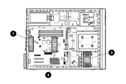
Component identification
Front panel components
Item |
Description |
|
|
1 |
Media drive bay |
2 |
USB connectors (4) |
Front panel LEDs and buttons
Component identification 7

Item |
Description |
Status |
|
|
|
1 |
System health LED |
Green = Normal |
|
|
Amber = System degraded |
|
|
Red = System critical |
|
|
|
2 |
NIC 1 link/activity LED |
Green = Network link |
|
|
Flashing green = Network link and activity |
|
|
Off = No link to network (If the power is off, view the rear panel NIC |
|
|
LEDs for status.) |
|
|
|
3 |
Drive activity LED |
Flashing green = Drive active |
|
|
Off = No drive activity |
|
|
|
4 |
System power button/LED |
Green = System on |
|
|
Amber = System in standby, but power is still applied |
|
|
Off = Power cord not attached or power supply failed |
|
|
|
5 |
Power status LED |
Green = System on |
|
|
Amber = System in standby, but power is still applied |
|
|
Off = Power cord not attached or power supply failed |
|
|
|
6 |
NIC 2 link/activity LED |
Green = Network link |
|
|
Flashing green = Network link and activity |
|
|
Off = No link to network (If the power is off, view the rear panel NIC |
|
|
LEDs for status.) |
|
|
|
7 |
UID button/LED |
Blue = Activated |
|
|
Flashing blue = System being remotely managed |
|
|
Off = Deactivated |
|
|
|
8 |
Optical drive activity LED |
Flashing green = Drive active |
|
|
Off = No drive activity |
|
|
|
Rear panel components
Item Description
1Kensington lock notch
2Power supply connector
3PCIe slot cover retainer latch
Component identification 8
4 |
Slot 1 |
PCIe2x16 (16, 8, 4, 1) |
5 |
Slot 2 |
PCIe2x8 (4, 1) |
6 |
Slot 3 |
PCIe2x8 (4, 1) |
7 |
Slot 4 |
PCIe2x4 (1) |
8 |
USB connectors (4) |
|
9 |
HP dedicated iLO management port (option) |
|
10 |
UID button/LED |
|
11 |
10/100/1000 NIC1 connector/shared iLO management port |
|
12 |
10/100/1000 NIC2 connector |
|
13 |
Video connector |
|
14 |
Serial connector |
|
Rear panel LEDs and buttons
Item |
Description |
Status |
|
|
|
1 |
UID LED/button |
Flashing blue = Activated |
|
|
Off = System being managed remotely/deactivated |
2 |
HP dedicated iLO |
Green = Network link |
|
management port |
Flashing green = Network link and activity |
|
option LEDs |
Off = No link to network |
|
|
|
3 |
NIC activity LED |
Green = Network activity |
|
|
Flashing green = Network activity |
|
|
Off = No network activity |
|
|
|
4 |
NIC link LED |
Green = Network link |
|
|
Off = No network link |
|
|
|
Component identification 9
System board components
Item |
Description |
|
|
1 |
Dedicated iLO management module connector |
|
|
2 |
System maintenance switch |
3 |
RPS connector (1x5 pin) |
4 |
Front system fan connector (2x3 pin) |
5 |
Processor socket |
6 |
DIMM slots (4) |
7 |
24-pin power supply connector |
8 |
Processor-heatsink fan assembly connector (2x3 pin) |
9 |
Rear system fan connector (2x3 pin) |
10 |
RPS connector (2x8 pin) |
11 |
Internal USB connector |
12 |
System battery |
13 |
I2C cable connector |
14 |
SATA connectors (2) |
15 |
SMB bus connector |
16 |
Temperature sensor connector |
17 |
SD card connector |
18 |
Mini-SAS connector |
19 |
Front I/O connector |
20 |
Front USB connectors (2) |
21 |
Slot 1 PCIe2x16 (16, 8, 4, 1) |
22 |
Slot 2 PCIe2x8 (4, 1) |
23 |
Slot 3 PCIe2x8 (4, 1) |
24 |
Slot 1 PCIe2x4 (1) |
25 |
4-pin power supply connector |
26 |
TPM connector |
Component identification 10
Item Description
27Rear USB connectors (4)
28NMI header
DIMM slot locations
DIMM slots are numbered sequentially (1 through 4) for the processor.
System maintenance switch
Position |
Default |
Function |
|
|
|
1 |
Off |
Off = iLO security is enabled |
|
|
On = iLO security is disabled |
|
|
|
2 |
Off |
Off = System configuration can be |
|
|
changed |
|
|
On = System configuration is locked |
|
|
|
3 |
— |
Reserved |
4 |
— |
Reserved |
5 |
Off |
Off = Power-on password is enabled |
|
|
On = Power-on password is disabled |
|
|
|
6 |
Off |
Off = No function |
|
|
On = Clear NVRAM |
|
|
|
7 |
— |
Reserved |
8 |
— |
Reserved |
9 |
— |
Reserved |
10 |
— |
Reserved |
When the system maintenance switch position 6 is set to the On position, the system is prepared to erase all system configuration settings from both CMOS and NVRAM.
Component identification 11

CAUTION: Clearing CMOS and/or NVRAM deletes configuration information. Be sure to properly configure the server or data loss could occur.
System board LEDs
Item |
LED description |
Status |
|
|
|
1 |
Power supply 1 |
Red = Power supply 1 failed |
|
failure |
Off = Normal |
|
|
|
2 |
Power supply 2 |
Red = Power supply 2 failed |
|
(redundant) failure |
Off = Normal |
NMI functionality
An NMI crash dump enables you to create crash dump files when a system is hung and not responding to traditional debug mechanisms.
Crash dump log analysis is an essential part of diagnosing reliability problems such as hangs in operating systems, device drivers, and applications. Many crashes freeze a system, and the only available action for administrators is to cycle the system power. Resetting the system erases any information that might support problem analysis, but the NMI feature preserves that information by performing a memory dump before a hard reset.
To force the OS to invoke the NMI handler and generate a crash dump log, do either of the following:
•Short the NMI header pins.
•Use the iLO Virtual NMI feature.
For more information, see the whitepaper on the HP website (http://h20000.www2.hp.com/bc/docs/support/SupportManual/c00797875/c00797875.pdf).
Component identification 12

SAS and SATA drive numbering
•Four-bay LFF drive model
•Eight-bay SFF drive model
Component identification 13

SAS and SATA drive LEDs
Item Description
1Fault/UID LED (amber/blue)
2Online LED (green)
SAS and SATA drive LED combinations
Online/activity |
Fault/UID LED |
Interpretation |
|
LED (green) |
(amber/blue) |
|
|
|
|
|
|
On, off, or |
Alternating amber and |
The drive has failed, or a predictive failure alert has been |
|
flashing |
blue |
received for this drive; it also has been selected by a management |
|
|
|
application. |
|
|
|
|
|
On, off, or |
Steadily blue |
The drive is operating normally, and it has been selected by a |
|
flashing |
|
management application. |
|
On |
Amber, flashing |
A predictive failure alert has been received for this drive. |
|
|
regularly (1 Hz) |
Replace the drive as soon as possible. |
|
On |
Off |
The drive is online, but it is not active currently. |
|
Flashing regularly |
Amber, flashing |
Do not remove the drive. Removing a drive may terminate the |
|
(1 Hz) |
regularly (1 Hz) |
current operation and cause data loss. |
|
|
|
The drive is part of an array that is undergoing capacity |
|
|
|
expansion or stripe migration, but a predictive failure alert has |
|
|
|
been received for this drive. To minimize the risk of data loss, do |
|
|
|
not replace the drive until the expansion or migration is complete. |
|
|
|
|
|
Flashing regularly |
Off |
Do not remove the drive. Removing a drive may terminate the |
|
(1 Hz) |
|
current operation and cause data loss. |
|
|
|
The drive is rebuilding, or it is part of an array that is undergoing |
|
|
|
capacity expansion or stripe migration. |
|
|
|
|
|
Flashing |
Amber, flashing |
The drive is active, but a predictive failure alert has been received |
|
irregularly |
regularly (1 Hz) |
for this drive. Replace the drive as soon as possible. |
|
Flashing |
Off |
The drive is active, and it is operating normally. |
|
irregularly |
|
|
|
|
|
Component identification 14 |
|

Online/activity |
Fault/UID LED |
Interpretation |
LED (green) |
(amber/blue) |
|
|
|
|
Off |
Steadily amber |
A critical fault condition has been identified for this drive, and the |
|
|
controller has placed it offline. Replace the drive as soon as |
|
|
possible. |
|
|
|
Off |
Amber, flashing |
A predictive failure alert has been received for this drive. Replace |
|
regularly (1 Hz) |
the drive as soon as possible. |
Off |
Off |
The drive is offline, a spare, or not configured as part of an array. |
BBWC module LEDs
Item ID |
Color |
Description |
|
|
|
1 |
Green |
System Power LED. This LED illuminates steadily when the |
|
|
system is powered up and 12-V system power is available. |
|
|
This power supply is used to maintain the battery charge |
|
|
and provide supplementary power to the cache |
|
|
microcontroller. |
|
|
|
2 |
Green |
Auxiliary Power LED. This LED illuminates steadily when |
|
|
3.3V auxiliary voltage is detected. The auxiliary voltage is |
|
|
used to preserve BBWC data and is available any time that |
|
|
the system power cords are connected to a power supply. |
|
|
|
3 |
Amber |
Battery Health LED. To interpret the illumination patterns of |
|
|
this LED, see the following table. |
|
|
|
4 |
Green |
BBWC Status LED. To interpret the illumination patterns of |
|
|
this LED, see the following table. |
Component identification 15
LED3 pattern |
LED4 pattern |
Interpretation |
|
|
|
— |
One blink every |
The system is powered down, and the cache contains data that has not |
|
two seconds |
yet been written to the drives. Restore system power as soon as |
|
|
possible to prevent data loss. |
|
|
If 3.3 V auxiliary power is available, as indicated by LED 2, then data |
|
|
preservation time is extended. If no auxiliary power is available, only |
|
|
battery power preserves the data. A fully-charged battery can |
|
|
normally preserve data for at least two days. |
|
|
The battery lifetime also depends on the cache module size. For more |
|
|
information, see the controller QuickSpecs on the HP Product Bulletin |
|
|
website (http://www.hp.com/go/productbulletin). |
|
|
|
— |
Double blink, then |
The cache microcontroller is waiting for the host controller to |
|
pause |
communicate. |
— |
One blink per |
The battery pack is below the minimum charge level and is being |
|
second |
charged. Features that require a battery (such as write cache, capacity |
|
|
expansion, stripe size migration, and RAID migration) are temporarily |
|
|
unavailable until charging is complete. The recharge process takes |
|
|
between 15 minutes and 2 hours, depending on the initial capacity of |
|
|
the battery. |
|
|
|
— |
Steady glow |
The battery pack is fully charged, and posted write data is stored in the |
|
|
cache. |
|
|
|
— |
Off |
The battery pack is fully charged, and write data is not posted in the |
|
|
cache. |
One blink per |
One blink per |
An alternating green and amber blink pattern indicates that the cache |
second |
second |
microcontroller is executing from within its boot loader and receiving |
|
|
new flash code from the host controller. |
Steady glow |
— |
There is a short circuit across the battery terminals or within the battery |
|
|
pack. BBWC features are disabled until the battery pack is replaced. |
|
|
The life expectancy of a battery pack is typically more than three |
|
|
years. |
|
|
|
One blink per |
— |
An open circuit is across the battery terminals or within the battery |
second |
|
pack. BBWC features are disabled until the battery pack is replaced. |
|
|
The life expectancy of a battery pack is typically more than three |
|
|
years. |
|
|
|
Component identification 16
FBWC module LEDs
The FBWC module has two single-color LEDs (green and amber). The LEDs are duplicated on the reverse side of the cache module to facilitate status viewing.
1 Green LED |
2 Amber LED |
Interpretation |
|
|
|
Off |
On |
A backup is in progress. |
Flashing (1 Hz) |
On |
A restore is in progress. |
Flashing (1 Hz) |
Off |
The capacitor pack is charging. |
On |
Off |
The capacitor pack has completed charging. |
Flashing (2 Hz) |
Flashing (2 Hz) |
One of the following conditions exists: |
Alternating with |
Alternating with |
• The charging process has timed out. |
amber LED |
green LED |
• The capacitor pack is not connected. |
|
|
|
On |
On |
The flash code image failed to load. |
Off |
Off |
The flash code is corrupt. |
Component identification 17
Fan locations
Item |
Description |
|
|
1 |
Rear system fan (for processor cooling) |
2 |
Processor-heatsink fan assembly |
3 |
Front system fan (for expansion board cooling |
Component identification 18

Operations
Power up the server
1.Connect each power cord to the server.
2.Connect each power cord to the power source.
3.Press the Power On/Standby button.
The server exits standby mode and applies full power to the system. The system power LED changes from amber to green.
Power down the server
Before powering down the server for any upgrade or maintenance procedures, perform a backup of critical server data and programs.
WARNING: To reduce the risk of personal injury, electric shock, or damage to the equipment, remove the power cord to remove power from the server. The front panel Power On/Standby button does not completely shut off system power. Portions of the power supply and some internal circuitry remain active until AC power is removed.
IMPORTANT: When the server is in standby mode, auxiliary power is still being provided to the system.
To power down the server, use one of the following methods:
•Press and release the Power On/Standby button.
This method initiates a controlled shutdown of applications and the OS before the server enters standby mode.
•Press and hold the Power On/Standby button for more than 4 seconds to force the server to enter standby mode.
This method forces the server to enter standby mode without properly exiting applications and the OS. If an application stops responding, you can use this method to force a shutdown.
•Use a virtual power button selection through iLO.
This method initiates a controlled remote shutdown of applications and the OS before the server enters standby mode.
Before proceeding, verify the server is in standby mode by observing that the system power LED is amber.
Operations 19

Unlock and open the tower bezel
The tower bezel must be unlocked and opened to access the drive cage and media bays. It must be unlocked to remove the access panel. The bezel must remain closed during normal server operations.
Remove the tower bezel
1.Unlock and open the tower bezel (on page 20).
2.Pull the bezel away from the front chassis.
Install the tower bezel
1.Insert the tabs on the tower bezel into the slots on the front chassis.
Operations 20
2.Close and lock the tower bezel.
Remove the access panel
WARNING: To reduce the risk of personal injury from hot surfaces, allow the drives and the internal system components to cool before touching them.
CAUTION: For proper cooling, do not operate the server without the access panel, baffles, expansion slot covers, or blanks installed. If the server supports hot-plug components, minimize the amount of time the access panel is open.
1.Power down the server (on page 19).
2.Remove all power:
a.Disconnect each power cord from the power source.
b.Disconnect each power cord from the server.
3.Unlock the tower bezel ("Unlock and open the tower bezel" on page 20).
4.Place the server on its side.
5.Remove the thumbscrew on the access panel.
6.Slide the access panel back.
7.Lift the access panel away from the chassis.
Install the access panel
CAUTION: Do not operate the server for long periods with the access panel open or removed. Operating the server in this manner results in improper airflow and improper cooling that can lead to thermal damage.
1.Place the access panel on the chassis, and then slide it toward the front of the server.
2.Tighten the thumbscrew.
3.Close and lock the tower bezel.
Operations 21
4.Connect each power cord to the server.
5.Connect each power cord to the power source.
IMPORTANT: Be sure that the panel is locked into place securely before powering up the server.
6.Power up the server (on page 19).
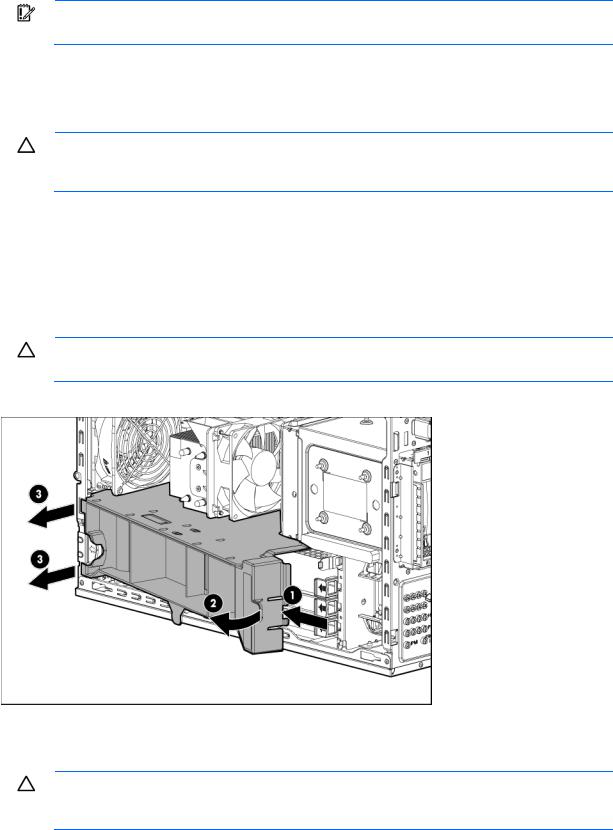
Remove the air baffle
CAUTION: For proper cooling, do not operate the server without the access panel, baffles, expansion slot covers, or blanks installed. If the server supports hot-plug components, minimize the amount of time the access panel is open.
1.Power down the server (on page 19).
2.Remove all power:
a.Disconnect each power cord from the power source.
b.Disconnect each power cord from the server.
3.Unlock the tower bezel ("Unlock and open the tower bezel" on page 20).
4.Remove the access panel (on page 21).
CAUTION: Do not detach the cable that connects the battery pack to the cache module. Detaching the cable causes any unsaved data in the cache module to be lost.
5.Remove the air baffle.
Install the air baffle
CAUTION: For proper cooling, do not operate the server without the access panel, baffles, expansion slot covers, or blanks installed. If the server supports hot-plug components, minimize the amount of time the access panel is open.
Operations 22
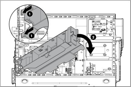
1.Insert the tabs on the baffle into the slots on the rear chassis.
2.Push the front end of the baffle inside the chassis.
3.Install the access panel (on page 21).
4.Lock the tower bezel.
5.Connect each power cord to the server.
6.Connect each power cord to the power source.
7.Power up the server (on page 19).
Operations 23

Setup
Optional installation services
Delivered by experienced, certified engineers, HP Care Pack services help you keep your servers up and running with support packages tailored specifically for HP ProLiant systems. HP Care Packs let you integrate both hardware and software support into a single package. A number of service level options are available to meet your needs.
HP Care Pack Services offer upgraded service levels to expand your standard product warranty with easy-to-buy, easy-to-use support packages that help you make the most of your server investments. Some of the Care Pack services are:
•Hardware support
o 6-Hour Call-to-Repair
o 4-Hour 24x7 Same Day
o 4-Hour Same Business Day
•Software support
o Microsoft® operating systems o Linux operating systems
o HP ProLiant Essentials (HP SIM and RDP)
•Integrated hardware and software support o Critical Service
o Proactive 24 o Support Plus
o Support Plus 24
•Startup and implementation services for both hardware and software
For more information on HP Care Pack Services, see the HP website (http://www.hp.com/services/carepack).
Optimum environment
When installing the server, select a location that meets the environmental standards described in this section.
Space and airflow requirements
Leave at least a 7.6-cm (3-inch) clearance space at the front and back of the server for proper ventilation.
Setup 24

Temperature requirements
To ensure continued, safe, and reliable equipment operation, install or position the system in a well-ventilated, climate-controlled environment.
The maximum recommended TMRA for most server products is 35°C (95°F). The temperature in the room where the server is located must not exceed 35°C (95°F).
CAUTION: To reduce the risk of damage to the equipment when installing third-party options:
•Do not permit optional equipment to impede airflow around the server beyond the maximum allowable limits.
•Do not exceed the manufacturer’s TMRA.
Power requirements
Installation of this equipment must comply with local and regional electrical regulations governing the installation of information technology equipment by licensed electricians. This equipment is designed to operate in installations covered by NFPA 70, 1999 Edition (National Electric Code) and NFPA-75, 1992 (code for Protection of Electronic Computer/Data Processing Equipment). For electrical power ratings on options, see the product rating label or the user documentation supplied with that option.
CAUTION: Protect the server from power fluctuations and temporary interruptions with a regulating uninterruptible power supply. This device protects the hardware from damage caused by power surges and voltage spikes and keeps the system in operation during a power failure.
When installing more than one server, you might have to use additional power distribution devices to safely provide power to all devices. Observe the following guidelines:
•Balance the server power load between available AC supply branch circuits.
•Do not allow the overall system AC current load to exceed 80% of the branch circuit AC current rating.
•Do not use common power outlet strips for this equipment.
•Provide a separate electrical circuit for the server.
Electrical grounding requirements
The server must be grounded properly for proper operation and safety. In the United States, you must install the equipment in accordance with NFPA 70, 1999 Edition (National Electric Code), Article 250, as well as any local and regional building codes. In Canada, you must install the equipment in accordance with Canadian Standards Association, CSA C22.1, Canadian Electrical Code. In all other countries, you must install the equipment in accordance with any regional or national electrical wiring codes, such as the International Electrotechnical Commission (IEC) Code 364, parts 1 through 7. Furthermore, you must be sure that all power distribution devices used in the installation, such as branch wiring and receptacles, are listed or certified grounding-type devices.
Because of the high ground-leakage currents associated with multiple servers connected to the same power source, HP recommends the use of a PDU that is either permanently wired to the building’s branch circuit or includes a nondetachable cord that is wired to an industrial-style plug. NEMA locking-style plugs or those complying with IEC 60309 are considered suitable for this purpose. Using common power outlet strips for the server is not recommended.
Setup 25

Identifying the contents of the server shipping carton
Unpack the server shipping carton and locate the materials and documentation necessary for installing the server.
The contents of the server shipping carton include:
•Server
•Power cord
•Hardware documentation, Documentation CD, and software products In addition to the supplied items, you might need:
•Operating system or application software
•Hardware options
Installing hardware options
Install any hardware options before initializing the server. For options installation information, refer to the option documentation. For server-specific information, refer to "Hardware options installation (on page 30)."
Setting up a tower server
To set up a tower server, follow these steps. To install the server into a rack, see Installing a server into a rack ("Installing a server in a rack" on page 26).
1.Connect peripheral devices to the server.
WARNING: To reduce the risk of electric shock, fire, or damage to the equipment, do not plug telephone or telecommunications connectors into NIC connectors.
2.Connect the power cord to the rear of the server.
3.Connect the power cord to the AC power source.
WARNING: To reduce the risk of electric shock or damage to the equipment:
•Do not disable the power cord grounding plug. The grounding plug is an important safety feature.
•Plug the power cord into a grounded (earthed) electrical outlet that is easily accessible at all times.
•Unplug the power cord from the power supply to disconnect power to the equipment.
•Do not route the power cord where it can be walked on or pinched by items placed against it. Pay particular attention to the plug, electrical outlet, and the point where the cord extends from the server.
Installing a server in a rack
The procedure to install the tray in the rack is similar to the procedures to install a server in a rack. For more information, see the 2U Quick Deploy Rail System Installation Instructions that shipped in the rail kit.
Setup 26

CAUTION: To avoid damage to the equipment, be sure that the rack rails are installed in a predetermined location on the rack so that airflow clearance issues are resolved. For airflow clearance information, refer to the documentation that ships with the server.
To install the component:
1.See the "Installing the Product into a Rack" section of the 2U Quick Deploy Rack Rail System Installation Instructions to do the following:
a.Install the component rails on the tray.
b.Install the rack rails in the rack.
2.Install the tray onto the rack rails, and then partially slide the assembly into the rack.
3.Attach the straps to the tray.
4.Place the server on the tray, and then secure the server to the tray.
Setup 27

CAUTION: To prevent damage to equipment, do not place the monitor on a rack-mounted server. The rack enabling kit supports only the server.
5.Slide the tray fully into the rack, and then tighten the thumbscrews.
6.Slide the locking bracket forward, and then tighten the thumbscrews.
Powering up and configuring the server
To power up the server, press the Power On/Standby button.
While the server boots, RBSU and the ORCA utility are automatically configured to prepare the server for operating system installation.
To configure these utilities manually:
•Press the F8 key when prompted during the array controller initialization to configure the array controller using ORCA.
Setup 28
•Press the F9 key when prompted during the boot process to change the server settings using RBSU. The system is set up by default for the English language.
For more information on the automatic configuration, refer to the HP ROM-Based Setup Utility User Guide located on the Documentation CD.
Installing the operating system
To operate properly, the server must have a supported operating system installed. For the latest information on supported operating systems, see the HP website (http://www.hp.com/go/supportos).
Methods to install an operating system on the server include:
•SmartStart assisted installation—Insert the SmartStart CD into the DVD-ROM drive and reboot the server.
•Manual installation—Insert the operating system CD into the DVD-ROM drive and reboot the server. You might have to obtain additional drivers from the HP website (http://www.hp.com/support).
For more information, see the SmartStart installation poster in the HP ProLiant Essentials Foundation Pack included with the server.
Registering the server
To register the server, see the HP Registration website (http://register.hp.com).
Setup 29

Hardware options installation
Introduction
If more than one option is being installed, read the installation instructions for all the hardware options and identify similar steps to streamline the installation process.
WARNING: To reduce the risk of personal injury from hot surfaces, allow the drives and the internal system components to cool before touching them.
CAUTION: To prevent damage to electrical components, properly ground the server before beginning any installation procedure. Improper grounding can cause electrostatic discharge.
HP product QuickSpecs
For more information about product features, specifications, options, configurations, and compatibility, see the product QuickSpecs on the HP Product Bulletin website (http://www.hp.com/go/productbulletin).
SAS and SATA drive options
The server provides non-hot-plug capability through an embedded SATA controller. To obtain hot-plug capability, install an optional controller and hot-plug cable option kit. The server supports up to four non-hot-plug or hot-plug LFF drives and up to eight hot-plug SFF drives.
Drive installation guidelines
When adding drives to the server, observe the following general guidelines:
•The system automatically sets all drive numbers.
•If only one drive is used, install it in the bay with the lowest drive number.
•When drives are grouped together into the same drive array, they must be of the same capacity to provide the greatest storage space efficiency.
Optional storage controllers provide support for hot-plug capability and drive LEDs. Controller options are:
•The embedded controller supports non-hot-plug SATA drives. Drive LEDs are not supported.
•Optional SATA controllers support hot-plug SATA drives and drive LEDs.
•Optional SAS controllers support hot-plug SAS or SATA drives and drive LEDs.
Installing a drive
CAUTION: To prevent improper cooling and thermal damage, do not operate the server unless all bays are populated with either a component or a blank.
Hardware options installation 30
Loading...