


HP ProLiant DL320 Generation 3 Server
User Guide
March 2005 (Second Edition)
Part Number 374263-002
© Copyright 2004, 2005 Hewlett-Packard Development Company, L.P.
The information contained herein is subject to change without notice. The only warranties for HP products and services are set forth in the express warranty statements accompanying such products and services. Nothing herein should be construed as constituting an additional warranty. HP shall not be liable for technical or editorial errors or omissions contained herein.
Microsoft, Windows, and Windows NT are U.S. registered trademarks of Microsoft Corporation.
Linux is a U.S. registered trademark of Linus Torvalds.
March 2005 (Second Edition)
Part Number 374263-002
Audience assumptions
This document is for the person who installs, administers, and troubleshoots servers and storage systems. HP assumes you are qualified in the servicing of computer equipment and trained in recognizing hazards in products with hazardous energy levels.

|
3 |
Contents |
|
Server component identification |
7 |
Front panel components ....................................................................................................................... |
7 |
Front panel LEDs and buttons.............................................................................................................. |
8 |
Rear panel components ...................................................................................................................... |
10 |
Rear panel LEDs and buttons............................................................................................................. |
11 |
System board components ................................................................................................................. |
12 |
System maintenance switch.................................................................................................... |
13 |
NMI switch............................................................................................................................. |
14 |
System board LEDs ........................................................................................................................... |
14 |
System LEDs and internal health LED combinations........................................................................ |
15 |
Internal USB connector...................................................................................................................... |
17 |
SCSI IDs and SATA device numbers ................................................................................................ |
17 |
Fan module location........................................................................................................................... |
18 |
Server operations |
19 |
Powering up the server....................................................................................................................... |
19 |
Powering down the server.................................................................................................................. |
19 |
Preparation procedures....................................................................................................................... |
20 |
Extending the server from the rack .................................................................................................... |
21 |
Removing the access panel ................................................................................................................ |
21 |
Installing the access panel.................................................................................................................. |
22 |
Removing the PCI riser board assembly ............................................................................................ |
22 |
Installing PCI riser board assembly ................................................................................................... |
23 |
Removing the hot-plug SATA backplane .......................................................................................... |
24 |
Removing the fan assembly ............................................................................................................... |
25 |
Installing the fan assembly................................................................................................................. |
26 |
Server setup |
27 |
Optional installation services ............................................................................................................. |
27 |
Rack planning resources .................................................................................................................... |
28 |
Optimum environment ....................................................................................................................... |
29 |
Space and airflow requirements.............................................................................................. |
29 |
Temperature requirements ...................................................................................................... |
30 |
Power requirements ................................................................................................................ |
31 |
Electrical grounding requirements.......................................................................................... |
32 |
Rack warnings.................................................................................................................................... |
32 |
Identifying the server shipping carton contents ................................................................................. |
33 |

4 HP ProLiant DL320 Generation 3 Server User Guide
Installing hardware options ................................................................................................................ |
33 |
Installing the server into the rack ....................................................................................................... |
34 |
Powering up and configuring the server ............................................................................................ |
35 |
Installing the operating system........................................................................................................... |
35 |
Registering the server......................................................................................................................... |
36 |
Hardware options installation |
37 |
Introduction........................................................................................................................................ |
37 |
Memory options ................................................................................................................................. |
37 |
DIMM installation guidelines................................................................................................. |
38 |
Installing DIMMs ................................................................................................................... |
38 |
Hard drive options.............................................................................................................................. |
39 |
Removing a hard drive blank.................................................................................................. |
40 |
Hard drive guidelines.............................................................................................................. |
40 |
Installing a SATA hard drive.................................................................................................. |
40 |
Installing non-hot-plug hard drives......................................................................................... |
41 |
Installing the CD-ROM drive assembly............................................................................................. |
43 |
Installing the DVD-ROM drive assembly.......................................................................................... |
45 |
Installing the diskette drive assembly ................................................................................................ |
45 |
Installing a PCI SCSI array controller or a PCI SCSI controller........................................................ |
45 |
Server cabling |
47 |
Cabling overview ............................................................................................................................... |
47 |
Server cable routing ........................................................................................................................... |
47 |
SATA cable routing ........................................................................................................................... |
48 |
SCSI cable routing ............................................................................................................................. |
49 |
Server software and configuration utilities |
51 |
Configuration tools ............................................................................................................................ |
51 |
SmartStart software ................................................................................................................ |
51 |
HP ROM-Based Setup Utility ................................................................................................ |
53 |
Array Configuration Utility .................................................................................................... |
54 |
HP ProLiant Essentials Rapid Deployment Pack ................................................................... |
55 |
Re-entering the server serial number and product ID ............................................................. |
55 |
Management tools.............................................................................................................................. |
56 |
Automatic Server Recovery.................................................................................................... |
57 |
ROMPaq utility....................................................................................................................... |
57 |
System Online ROM flash component utility......................................................................... |
57 |
Integrated Lights-Out technology........................................................................................... |
58 |
Erase Utility............................................................................................................................ |
59 |
Management Agents ............................................................................................................... |
60 |
HP Systems Insight Manager.................................................................................................. |
60 |
Redundant ROM support........................................................................................................ |
61 |
USB support and functionality ............................................................................................... |
62 |

Contents |
5 |
Diagnostic tools ................................................................................................................................. |
63 |
Survey Utility ......................................................................................................................... |
63 |
Array Diagnostic Utility ......................................................................................................... |
64 |
HP Insight Diagnostics ........................................................................................................... |
64 |
Integrated Management Log................................................................................................... |
64 |
Keeping the system current................................................................................................................ |
65 |
Drivers .................................................................................................................................... |
65 |
Resource Paqs......................................................................................................................... |
66 |
ProLiant Support Packs .......................................................................................................... |
66 |
Operating system version support........................................................................................... |
66 |
Change control and proactive notification.............................................................................. |
66 |
Care Pack................................................................................................................................ |
67 |
Battery replacement |
69 |
Troubleshooting |
71 |
Server diagnostic steps....................................................................................................................... |
71 |
Important safety information.............................................................................................................. |
72 |
Symbols on equipment ........................................................................................................... |
72 |
Warnings and cautions............................................................................................................ |
73 |
Preparing the server for diagnosis...................................................................................................... |
75 |
Symptom information ........................................................................................................................ |
76 |
Service notifications........................................................................................................................... |
77 |
Loose connections.............................................................................................................................. |
77 |
Diagnostic steps ................................................................................................................................. |
77 |
Start diagnosis flowchart ........................................................................................................ |
78 |
General diagnosis flowchart ................................................................................................... |
80 |
Power-on problems flowchart................................................................................................. |
82 |
POST problems flowchart ...................................................................................................... |
85 |
OS boot problems flowchart................................................................................................... |
87 |
Server fault indications flowchart........................................................................................... |
90 |
Other information resources............................................................................................................... |
93 |
Electrostatic discharge |
95 |
Preventing electrostatic discharge...................................................................................................... |
95 |
Grounding methods to prevent electrostatic discharge ...................................................................... |
96 |
Regulatory compliance notices |
97 |
Regulatory compliance identification numbers.................................................................................. |
97 |
Federal Communications Commission notice.................................................................................... |
98 |
FCC rating label...................................................................................................................... |
98 |
Class A equipment.................................................................................................................. |
98 |
Class B equipment .................................................................................................................. |
99 |

6 HP ProLiant DL320 Generation 3 Server User Guide
Declaration of conformity for products marked with the FCC logo, United States only |
................... 99 |
Modifications ................................................................................................................................... |
100 |
Cables............................................................................................................................................... |
100 |
Mouse compliance statement ........................................................................................................... |
100 |
Canadian notice (Avis Canadien)..................................................................................................... |
100 |
European Union regulatory notice ................................................................................................... |
101 |
Japanese notice................................................................................................................................. |
102 |
BSMI notice ..................................................................................................................................... |
102 |
Korean notice A&B ......................................................................................................................... |
103 |
Laser compliance ............................................................................................................................. |
103 |
Battery replacement notice............................................................................................................... |
104 |
Taiwan battery recycling notice ....................................................................................................... |
105 |
Power cord statement for Japan ....................................................................................................... |
105 |
Server specifications |
107 |
Environmental specifications ........................................................................................................... |
107 |
Server specifications ........................................................................................................................ |
107 |
Technical support |
109 |
Related documents ........................................................................................................................... |
109 |
HP contact information .................................................................................................................... |
109 |
Customer self repair ......................................................................................................................... |
110 |
Acronyms and abbreviations |
111 |
Index |
117 |
|
7 |
Server component identification |
|
In this section |
|
Front panel components.................................................................................................................. |
7 |
Front panel LEDs and buttons ........................................................................................................ |
8 |
Rear panel components................................................................................................................. |
10 |
Rear panel LEDs and buttons ....................................................................................................... |
11 |
System board components ............................................................................................................ |
12 |
System board LEDs ...................................................................................................................... |
14 |
System LEDs and internal health LED combinations .................................................................. |
15 |
Internal USB connector ................................................................................................................ |
17 |
SCSI IDs and SATA device numbers........................................................................................... |
17 |
Fan module location ..................................................................................................................... |
18 |
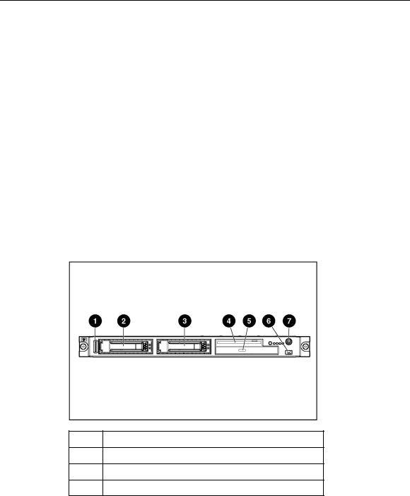
Front panel components
Item Description
1Serial label pull tab
2Hard drive bay 1
3Hard drive bay 2
8 HP ProLiant DL320 Generation 3 Server User Guide
Item Description
4Diskette drive bay
5Optical device bay
6Front USB port
7Power button
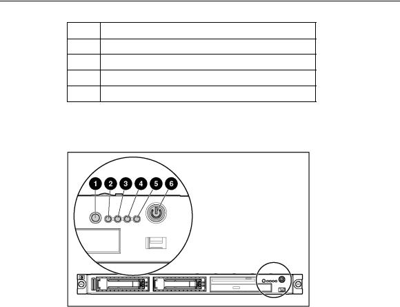
Front panel LEDs and buttons
Item |
Description |
Status |
|
|
|
1 |
UID button/LED |
Blue = Identification is activated. |
|
|
Flashing blue = System is being remotely managed. |
|
|
Off = Identification is deactivated. |
|
|
|
2 |
Internal health LED |
Green = System health is normal. |
|
|
Amber = System is degraded. To identify the component in a |
|
|
degraded state, refer to system board LEDs (on page 14). |
|
|
Red = System critical. To identify the component in a critical |
|
|
state, refer to system board LEDs (on page 14). |
|
|
Off = System health is normal (when in standby mode). |
|
|
|
|
|
|
Server component identification |
9 |
|
|
|
|
|
|
|
|
Item |
Description |
Status |
|
|
|
|
|
|
|
|
|
3 |
NIC 1 link/activity LED |
Green = Network link exists. |
|
|
|
|
|
Flashing green = Network link and activity exist. |
|
|
|
|
|
Off = No link to network exists. |
|
|
|
|
|
If power is off, view the LEDs on the RJ-45 connector for status |
|
|
|
|
|
by referring to the rear panel LEDs ("Rear panel LEDs and |
|
|
|
|
|
buttons" on page 11). |
|
|
|
|
|
|
|
|
|
4 |
NIC 2 link/activity LED |
Green = Network link exists. |
|
|
|
|
|
Flashing green = Network link and activity exist. |
|
|
|
|
|
Off = No link to network exists. |
|
|
|
|
|
If power is off, the front panel LED is not active. View the LEDs |
|
|
|
|
|
on the RJ-45 connector for status by referring to the rear panel |
|
|
|
|
|
LEDs ("Rear panel LEDs and buttons" on page 11). |
|
|
|
|
|
|
|
|
|
5 |
Drive activity LED |
Green = Drive activity is normal. |
|
|
|
|
|
Amber = Drive failure occurred. |
|
|
|
|
|
Off = No drive activity. |
|
|
|
|
|
|
|
|
|
6 |
Power On/Standby button |
Green = System is on. |
|
|
|
|
and system power LED |
Amber = System is shut down, but power is still applied. |
|
|
|
|
|
|
|
|
|
|
|
Off = Power cord is not attached, power supply failure has |
|
|
|
|
|
occurred, no power supplies are installed, facility power is not |
|
|
|
|
|
available, or the DC-to-DC converter is not installed. |
|
|
|
|
|
|
|
|
10 HP ProLiant DL320 Generation 3 Server User Guide
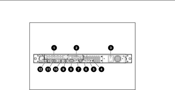
Rear panel components
Item |
Description |
|
|
1 |
PCI-X expansion slot 2, full-length 64 bit/133 MHz |
|
3.3 V (optional PCI Express slot 1, x8) |
|
|
2 |
PCI-X expansion slot 1, low-profile half-length |
|
64 bit/100 MHz 3.3 V |
|
|
3 |
Power supply |
|
|
4 |
UID button/LED |
|
|
5 |
10/100/1000 NIC 2 |
|
|
6 |
10/100/1000 NIC 1 |
|
|
7 |
iLO management port |
|
|
8 |
Serial connector |
|
|
9 |
Keyboard connector |
|
|
10 |
Mouse connector |
|
|
11 |
Video connector |
|
|
12 |
USB connectors |
|
|
Server component identification |
11 |
Rear panel LEDs and buttons
Item |
Description |
Status |
|
|
|
1 |
iLO activity |
Green = Activity exists. |
|
|
Flashing green = Activity exists. |
|
|
Off = No activity exists. |
|
|
|
2 |
iLO link |
Green = Link exists. |
|
|
Off = No link exists. |
|
|
|
3 |
10/100/1000 |
Green = Link exists. |
|
NIC 1 activity |
Flashing green = Activity exists. |
|
|
Off = No link exists. |
|
|
|
4 |
10/100/1000 |
Green = Link exists. |
|
NIC 1 link |
Off = No link exists. |
|
|
|
5 |
10/100/1000 |
Green = Link exists. |
|
NIC 2 link |
Off = No link exists. |
|
|
|
6 |
10/100/1000 |
Green = Activity exists. |
|
NIC 2 activity |
Flashing green = Activity exists. |
|
|
Off = No activity exists. |
|
|
|

12 HP ProLiant DL320 Generation 3 Server User Guide
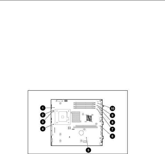
System board components
Item |
Description |
Item |
Description |
|
|
|
|
1 |
Rear USB connectors (2) |
16 |
Fan 1 connector |
|
|
|
|
2 |
Video connector |
17 |
Processor socket |
|
|
|
|
3 |
Mouse connector |
18 |
Fan 2 connector |
|
|
|
|
4 |
Keyboard connector |
19 |
Fan 3 connector |
|
|
|
|
5 |
Serial connector |
20 |
CD-ROM IDE connector |
|
|
|
|
6 |
iLO management port |
21 |
Fan 4 connector |
|
|
|
|
7 |
10/100/1000 NIC 1 |
22 |
Front USB connectors (2) |
|
|
|
|
8 |
10/100/1000 NIC 2 |
23 |
Front panel LED board |
|
|
|
connector |
|
|
|
|
9 |
UID button/LED |
24 |
Diskette drive connector |
|
|
|
|
10 |
DIMM slot 1 (Bank A) |
25 |
SATA hard drive connector 2 |
|
|
|
|
11 |
DIMM slot 2 (Bank A) |
26 |
SATA hard drive connector 1 |
|
|
|
|
12 |
DIMM slot 3 (Bank B) |
27 |
Battery |
|
|
|
|
13 |
DIMM slot 4 (Bank B) |
28 |
PCI-X 133-MHz or PCI |
|
|
|
Express connector* |
|
|
|
|
14 |
Power connector |
29 |
PCI 100-MHz connector |
|
|
|
|
Server component identification |
13 |
Item |
Description |
Item |
Description |
15 Power connector
*Designations if the optional PCI riser board is installed.
System maintenance switch
Position |
Default |
Function |
|
|
|
S1 |
Off |
Reserved |
|
|
|
S2 |
Off |
Off = Normal operation |
|
|
On = RBSU will not commit any |
|
|
configuration changes * |
|
|
|
S3 |
Off |
Reserved |
|
|
|
S4 |
Off |
Off = Normal operation |
|
|
On = Override RBSU setting and |
|
|
enable diskette boot * |
|
|
|
S5 |
Off |
Off = Power-on password enabled |
|
|
On = Power-on password disabled * |
|
|
|
S6 |
Off |
Off = Normal operation |
|
|
On = BIOS will clear CMOS and |
|
|
NVRAM * |
|
|
|
S7 |
Off |
Reserved |
|
|
|
S8 |
Off |
Reserved |
|
|
|
* "On" activates the function.
14 HP ProLiant DL320 Generation 3 Server User Guide
NMI switch
The NMI switch allows administrators to perform a memory dump before performing a hard reset. Crash dump analysis is an essential part of eliminating reliability problems, such as hangs or crashes in operating systems, device drivers, and applications. Many crashes freeze a system, requiring you to do a hard reset. Resetting the system erases any information that would support root cause analysis.
Systems running Microsoft® Windows® operating systems experience a blue screen trap when the operating system crashes. When this happens, Microsoft® recommends that system administrators perform an NMI event by pressing a dump switch. The NMI event enables a hung system to become responsive again.
System board LEDs
Item |
LED Description |
Status |
|
|
|
1 |
PPM |
Amber = PPM has failed. |
|
|
Off = PPM is operating normally. |
|
|
|
2 |
Processor |
Amber = Processor has failed. |
|
|
Off = Processor is operating normally. |
|
|
|
|
|
|
Server component identification |
15 |
|
|
|
|
|
|
Item |
LED Description |
Status |
|
|
|
|
|
|
|
3 |
Overtemperature |
Amber = System has reached a cautionary |
|
|
|
|
or critical temperature level. |
|
|
|
|
Off = Temperature is OK. |
|
|
|
|
|
|
|
4 |
System fan module |
Amber = One fan in this module has failed. |
|
|
|
|
Red = Multiple fans in this module have |
|
|
|
|
failed. |
|
|
|
|
Off = All fans in this module are operating |
|
|
|
|
normally. |
|
|
|
|
|
|
|
5 |
Power supply signal |
Amber = Power supply signal cable is not |
|
|
|
|
connected. |
|
|
|
|
Off = Power supply signal cable is |
|
|
|
|
connected. |
|
|
|
|
|
|
|
6 |
PCI Riser interlock |
Amber = PCI riser cage not seated. |
|
|
|
|
Off = PCI riser cage is seated. |
|
|
|
|
|
|
|
7 |
DIMM 1 |
Amber = DIMM has failed. |
|
|
|
|
Off = DIMM is operating normally. |
|
|
|
|
|
|
|
8 |
DIMM 2 |
Amber = DIMM has failed. |
|
|
|
|
Off = DIMM is operating normally. |
|
|
|
|
|
|
|
9 |
DIMM 3 |
Amber = DIMM has failed. |
|
|
|
|
Off = DIMM is operating normally. |
|
|
|
|
|
|
|
10 |
DIMM 4 |
Amber = DIMM has failed. |
|
|
|
|
Off = DIMM is operating normally. |
|
|
|
|
|
|
System LEDs and internal health LED combinations
When the internal health LED on the front panel illuminates either amber or red, the server is experiencing a health event. Combinations of illuminated system LEDs and the internal health LED indicate system status.
The front panel health LEDs indicate only the current hardware status. In some situations, HP SIM may report server status differently than the health LEDs because the software tracks more system attributes.

16 HP ProLiant DL320 Generation 3 Server User Guide
System LED and |
Internal Health |
Status |
|
Color |
LED Color |
|
|
|
|
|
|
Processor failure |
Red |
One or more of the following conditions may exist: |
|
(Amber) |
|
• |
Processor has failed. |
|
|
||
|
|
• Processor failed over to the offline spare. |
|
|
|
• Processor is not installed in the socket. |
|
|
|
• |
Processor is unsupported. |
|
|
• ROM detects a failed processor during POST. |
|
|
|
|
|
|
Amber |
Processor is in a pre-failure condition. |
|
|
|
|
|
PPM failure (Amber) |
Red |
PPM has failed. |
|
|
|
|
|
DIMM failure, slot X |
Red |
• DIMM in slot X has failed. |
|
(Amber) |
|
• DIMM in slot X is an unsupported type, and no valid |
|
|
|
||
|
|
|
memory exists in another bank. |
|
|
|
|
|
Amber |
• DIMM in slot X has reached single-bit correctable |
|
|
|
|
error threshold. |
|
|
• DIMM in slot X is in a pre-failure condition. |
|
|
|
• DIMM in slot X is an unsupported type, but valid |
|
|
|
|
memory exists in another bank. |
|
|
|
|
DIMM failure, all slots |
Red |
No valid or usable memory is installed in the system. |
|
in one bank (Amber) |
|
|
|
|
|
|
|
Overtemperature |
Amber |
The Health Driver has detected a cautionary temperature |
|
(Amber) |
|
level. |
|
|
|
|
|
|
Red |
The server has detected a hardware critical temperature |
|
|
|
level. |
|
|
|
|
|
Riser interlock |
Red |
The PCI riser board assembly is not seated. |
|
(Amber) |
|
|
|
|
|
|
|
Fan module (Amber) |
Amber |
A redundant fan has failed. |
|
|
|
|
|
Fan module (Red) |
Red |
The minimum fan requirements are not being met in one |
|
|
|
or more of the fan modules. One or more fans have failed |
|
|
|
or are missing. |
|
|
|
|
|
Power supply signal |
Red |
The power supply signal cable is not connected to the |
|
interlock (Amber) |
|
system board. |
|
|
|
|
|

Server component identification |
17 |
Internal USB connector
For more information, refer to "Internal USB Functionality (on page 63)."
SCSI IDs and SATA device numbers
Item |
SCSI ID |
SATA Device Number |
|
|
|
1 |
0 |
1 |
|
|
|
18 HP ProLiant DL320 Generation 3 Server User Guide
Item |
SCSI ID |
SATA Device Number |
|
|
|
2 |
1 |
2 |
|
|
|
Fan module location

|
19 |
Server operations |
|
In this section |
|
Powering up the server ................................................................................................................. |
19 |
Powering down the server ............................................................................................................ |
19 |
Preparation procedures ................................................................................................................. |
20 |
Extending the server from the rack............................................................................................... |
21 |
Removing the access panel........................................................................................................... |
21 |
Installing the access panel ............................................................................................................ |
22 |
Removing the PCI riser board assembly ...................................................................................... |
22 |
Installing PCI riser board assembly.............................................................................................. |
23 |
Removing the hot-plug SATA backplane..................................................................................... |
24 |
Removing the fan assembly.......................................................................................................... |
25 |
Installing the fan assembly ........................................................................................................... |
26 |
Powering up the server
To power up the server, press the Power On/Standby button.
Powering down the server
 WARNING: To reduce the risk of personal injury, electric shock, or damage to the equipment, remove the power cord to remove power from the server. The front panel Power On/Standby button does not completely shut off system power. Portions of the power supply and some internal circuitry remain active until AC power is removed.
IMPORTANT: If installing a hot-plug device, it is not necessary to power down the server.
1.Back up the server data.
2.Shut down the operating system as directed by the operating system documentation.

20HP ProLiant DL320 Generation 3 Server User Guide
3.If the server is installed in a rack, press the UID LED button on the front panel. Blue LEDs illuminate on the front and rear panels of the server.
4.Press the Power On/Standby button to place the server in standby mode. When the server activates standby power mode, the system power LED changes to amber.
5.If the server is installed in a rack, locate the server by identifying the illuminated rear UID LED button.
6.Disconnect the power cords.
The system is now without power.
Preparation procedures
To access some components and perform certain service procedures, you must perform one or more of the following procedures:
•Extend the server from the rack, if applicable ("Extending the server from the rack" on page 21).
If you are performing service procedures in an HP, Compaq branded, telco, or third-party rack cabinet, you can use the locking feature of the rack rails to support the server and gain access to internal components.
For more information about telco rack solutions, refer to the RackSolutions.com website (http://www.racksolutions.com/hp).
•Power down the server ("Powering down the server" on page 19).
If you must remove a server from a rack or a non-hot-plug component from a server, power down the server.
•Remove the server from the rack.
If the rack environment, cabling configuration, or the server location in the rack creates awkward conditions, remove the server from the rack.
•Remove the access panel ("Removing the access panel" on page 21).
Server operations |
21 |
Extending the server from the rack
NOTE: If the optional cable management arm option is installed, you can extend the server without powering down the server or disconnecting peripheral cables and power cords. These steps are only necessary with the standard cable management solution.
1.Power down the server ("Powering down the server" on page 19).
2.Disconnect all peripheral cables and power cords from the server rear panel.
3.Loosen the thumbscrews that secure the server faceplate to the front of the rack.
 WARNING: To reduce the risk of personal injury or equipment damage, be sure that the rack is adequately stabilized before extending a component from the rack.
 WARNING: To reduce the risk of personal injury, be careful when pressing the server rail-release latches and sliding the server into the rack. The sliding rails could pinch your fingers.
4.After performing the installation or maintenance procedure, slide the server back into the rack:
a.Press the server rail-release latches and slide the server fully into rack.
b.Secure the server by tightening the thumbscrews.
5.Reconnect the peripheral cables and power cords.
Removing the access panel
 WARNING: To reduce the risk of personal injury from hot surfaces, allow the drives and the internal system components to cool before touching them.
 CAUTION: Do not operate the server for long periods with the access panel open or removed. Operating the server in this manner results in improper airflow and improper cooling that can lead to thermal damage.

22 HP ProLiant DL320 Generation 3 Server User Guide
1.Power down the server if the standard cable management solution is installed ("Powering down the server" on page 19).
NOTE: If the optional cable management arm is installed, you can extend the server and perform hot-plug installation or maintenance procedures without powering down the server.
2.Extend the server from the rack, if applicable ("Extending the server from the rack" on page 21).
3.Use a screwdriver to remove the captive screw.
4.Slide the access panel back and lift it off the server.
Installing the access panel
1.Place the access panel on top of the server, allowing it to extend past the rear of the server approximately 10 mm (0.39 in).
2.Slide the access panel forward to lock, and tighten the captive screw to secure the access panel to the server.
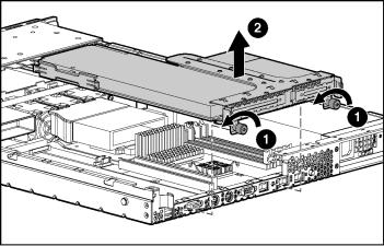
Removing the PCI riser board assembly
 CAUTION: To prevent damage to the server or expansion boards, power down the server and remove all AC power cords before removing or installing the PCI riser cage.
1.Power down the server ("Powering down the server" on page 19).
2.Extend the server from the rack, if applicable ("Extending the server from the rack" on page 21).
3.Remove the access panel ("Removing the access panel" on page 21).
4.Remove the PCI riser board assembly:
a.Disconnect any internal or external cables connected to any existing expansion boards.
b.Loosen the two PCI riser board assembly thumbscrews.
Server operations |
23 |
c.Lift the front of the assembly slightly and unseat the riser boards from the PCI riser board connectors.
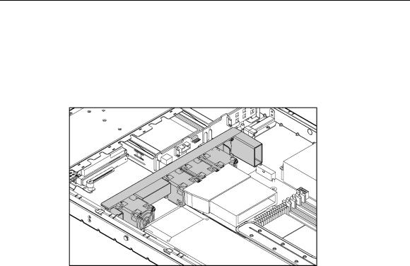
Installing PCI riser board assembly
 CAUTION: To prevent damage to the server or expansion boards, power down the server and remove all AC power cords before removing or installing the PCI riser board assembly.
1.Align the PCI riser board assembly with the corresponding connectors on the system board and install it into place.

24HP ProLiant DL320 Generation 3 Server User Guide
2.Tighten the two PCI riser board assembly thumbscrews.
Removing the hot-plug SATA backplane
1.Access the internal server components ("Preparation procedures" on page 20).
2.Disconnect the power cord and signal cables from the backplane.
3.Release the latch clip at the top middle of the backplane.
4.Remove the SATA backplane.
Server operations |
25 |
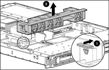
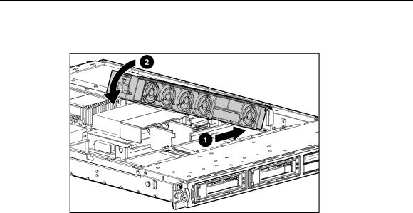
Removing the fan assembly
1.Power down the server ("Powering down the server" on page 19).
2.Extend the server from the rack, if applicable ("Extending the server from the rack" on page 21).
3.Remove the access panel ("Removing the access panel" on page 21).
4.Remove the fan assembly.
26 HP ProLiant DL320 Generation 3 Server User Guide
Installing the fan assembly

|
27 |
Server setup |
|
In this section |
|
Optional installation services........................................................................................................ |
27 |
Rack planning resources............................................................................................................... |
28 |
Optimum environment.................................................................................................................. |
29 |
Rack warnings .............................................................................................................................. |
32 |
Identifying the server shipping carton contents............................................................................ |
33 |
Installing hardware options .......................................................................................................... |
33 |
Installing the server into the rack ................................................................................................. |
34 |
Powering up and configuring the server....................................................................................... |
35 |
Installing the operating system ..................................................................................................... |
35 |
Registering the server ................................................................................................................... |
36 |
Optional installation services
Delivered by experienced, certified engineers, HP Care Pack services help you keep your servers up and running with support packages tailored specifically for HP ProLiant systems. HP Care Packs let you integrate both hardware and software support into a single package. A number of service level options are available to meet your needs.
HP Care Pack Services offer upgraded service levels to expand your standard product warranty with easy-to-buy, easy-to-use support packages that help you make the most of your server investments. Some of the Care Pack services are:
•Hardware support
–6-Hour Call-to-Repair
–4-Hour 24x7 Same Day
–4-Hour Same Business Day
•Software support
–Microsoft®
–Linux

28 HP ProLiant DL320 Generation 3 Server User Guide
– HP ProLiant Essentials (HP SIM and RDP)
•Startup and implementation services for both hardware and software
For more information on Care Packs, refer to the HP website (http://www.hp.com/hps/carepack/servers/cp_proliant.html).
Rack planning resources
The rack resource kit ships with all HP branded or Compaq branded 9000, 10000, and H9 series racks. A summary of the content of each resource follows:
•Custom Builder is a web-based service for configuring one or many racks. Rack configurations can be created using:
–A simple, guided interface
–Build-it-yourself mode
For more information, refer to the HP website (http://www.hp.com/products/configurator).
•The Installing Rack Products video provides a visual overview of operations required for configuring a rack with rack-mountable components. It also provides the following important configuration steps:
–Planning the site
–Installing rack servers and rack options
–Cabling servers in a rack
–Coupling multiple racks
•The Rack Products Documentation CD enables you to view, search, and print documentation for HP and Compaq branded racks and rack options. It also helps you set up and optimize a rack in a manner that best fits your environment.
If you intend to deploy and configure multiple servers in a single rack, refer to the white paper on high-density deployment on the HP website (http://www.hp.com/products/servers/platforms).
Server setup |
29 |
Optimum environment
When installing the server in a rack, select a location that meets the environmental standards described in this section.
Space and airflow requirements
To allow for servicing and adequate airflow, observe the following space and airflow requirements when deciding where to install a rack:
•Leave a minimum clearance of 122 cm (48 in) in front of the rack.
•Leave a minimum clearance of 76.2 cm (30 in) behind the rack.
•Leave a minimum clearance of 122 cm (48 in) from the back of the rack to the back of another rack when racks are back-to-back.
HP servers draw in cool air through the front door and expel warm air through the rear door. Therefore, the front and rear rack doors must be adequately ventilated to allow ambient room air to enter the cabinet, and the rear door must be adequately ventilated to allow the warm air to escape from the cabinet.
 CAUTION: To prevent improper cooling and damage to the equipment, do not block the ventilation openings.
When vertical space in the rack is not filled by a server or rack component, the gaps between the components cause changes in airflow through the rack and across the servers. Cover all gaps with blanking panels to maintain proper airflow.
 CAUTION: Always use blanking panels to fill empty vertical spaces in the rack. This arrangement ensures proper airflow. Using a rack without blanking panels results in improper cooling that can lead to thermal damage.
The Compaq 9000 and 10000 Series racks provide proper server cooling from flow-through perforations in the front and rear doors that provide 64 percent open area for ventilation.

30 HP ProLiant DL320 Generation 3 Server User Guide
 CAUTION: When using a Compaq branded 7000 Series rack, you must install the high airflow rack door insert [P/N 327281-B21 (42U) or P/N 157847-B21 (22U)] to provide proper front-to-back airflow and cooling.
 CAUTION: If a third-party rack is used, observe the following additional requirements to ensure adequate airflow and to prevent damage to the equipment:
•Front and rear doors—If the 42U rack includes closing front and rear doors, you must allow 5,350 sq cm (830 sq in) of holes evenly distributed from top to bottom to permit adequate airflow (equivalent to the required 64 percent open area for ventilation).
•Side—The clearance between the installed rack component and the side panels of the rack must be a minimum of 7 cm (2.75 in).
Temperature requirements
To ensure continued safe and reliable equipment operation, install or position the system in a well-ventilated, climate-controlled environment.
The maximum recommended ambient operating temperature (TMRA) for most server products is 35°C (95°F). The temperature in the room where the rack is located must not exceed 35°C (95°F).
 CAUTION: To reduce the risk of damage to the equipment when installing third-party options:
•Do not permit optional equipment to impede airflow around the server or to increase the internal rack temperature beyond the maximum allowable limits.
•Do not exceed the manufacturer’s TMRA.
 Loading...