


 Loading...
PR 30-HVSG A12
English
Printed: 07.05.2018 | Doc-Nr: PUB / 5376993 / 000 / 02
Printed: 07.05.2018 | Doc-Nr: PUB / 5376993 / 000 / 02

Contents |
|
|
1 |
Information about the documentation . . . . . . . . . . . . . . . . . . . . . . . . . . . . . . . . . . . . |
2 |
1.1 |
About this documentation . . . . . . . . . . . . . . . . . . . . . . . . . . . . . . . . . . . . . . . . . . . . . |
2 |
1.2 |
Explanation of symbols used . . . . . . . . . . . . . . . . . . . . . . . . . . . . . . . . . . . . . . . . . . . |
2 |
|
1.2.1 Warnings . . . . . . . . . . . . . . . . . . . . . . . . . . . . . . . . . . . . . . . . . . . . . . . . . . |
2 |
|
1.2.2 Symbols in the documentation . . . . . . . . . . . . . . . . . . . . . . . . . . . . . . . . . . . . . |
3 |
|
1.2.3 Symbols in the illustrations . . . . . . . . . . . . . . . . . . . . . . . . . . . . . . . . . . . . . . . |
3 |
1.3 |
On the product . . . . . . . . . . . . . . . . . . . . . . . . . . . . . . . . . . . . . . . . . . . . . . . . . . . |
3 |
1.4 |
Product information . . . . . . . . . . . . . . . . . . . . . . . . . . . . . . . . . . . . . . . . . . . . . . . . |
3 |
1.5 |
Declaration of conformity . . . . . . . . . . . . . . . . . . . . . . . . . . . . . . . . . . . . . . . . . . . . . |
3 |
1.6 |
Type approval test . . . . . . . . . . . . . . . . . . . . . . . . . . . . . . . . . . . . . . . . . . . . . . . . . |
4 |
2 |
Safety . . . . . . . . . . . . . . . . . . . . . . . . . . . . . . . . . . . . . . . . . . . . . . . . . . . . . . . . . |
4 |
2.1 |
Basic information concerning safety . . . . . . . . . . . . . . . . . . . . . . . . . . . . . . . . . . . . . . |
4 |
2.2 |
General safety measures . . . . . . . . . . . . . . . . . . . . . . . . . . . . . . . . . . . . . . . . . . . . . |
4 |
2.3 |
Proper preparation of the working area . . . . . . . . . . . . . . . . . . . . . . . . . . . . . . . . . . . . |
4 |
2.4 |
Electromagnetic compatibility . . . . . . . . . . . . . . . . . . . . . . . . . . . . . . . . . . . . . . . . . . |
5 |
2.5 |
Laser classification for Class 2 laser products . . . . . . . . . . . . . . . . . . . . . . . . . . . . . . . . |
5 |
2.6 |
Careful use of battery-powered tools . . . . . . . . . . . . . . . . . . . . . . . . . . . . . . . . . . . . . . |
5 |
3 |
Description . . . . . . . . . . . . . . . . . . . . . . . . . . . . . . . . . . . . . . . . . . . . . . . . . . . . . |
6 |
3.1 |
Product overview . . . . . . . . . . . . . . . . . . . . . . . . . . . . . . . . . . . . . . . . . . . . . . . . . . |
6 |
|
3.1.1 PR 30-HVSG A12 rotating laser . . . . . . . . . . . . . . . . . . . . . . . . . . . . . . . . . . . . |
6 |
|
3.1.2 PR 30-HVSG A12 control panel . . . . . . . . . . . . . . . . . . . . . . . . . . . . . . . . . . . . |
7 |
|
3.1.3 PRA 30G laser receiver and control panel . . . . . . . . . . . . . . . . . . . . . . . . . . . . . . |
7 |
|
3.1.4 PRA 30G laser receiver display . . . . . . . . . . . . . . . . . . . . . . . . . . . . . . . . . . . . . |
8 |
3.2 |
Intended use . . . . . . . . . . . . . . . . . . . . . . . . . . . . . . . . . . . . . . . . . . . . . . . . . . . . . |
8 |
3.3 |
Auto-leveling . . . . . . . . . . . . . . . . . . . . . . . . . . . . . . . . . . . . . . . . . . . . . . . . . . . . . |
8 |
3.4 |
Automatic alignment . . . . . . . . . . . . . . . . . . . . . . . . . . . . . . . . . . . . . . . . . . . . . . . . |
8 |
3.5 |
Inclination . . . . . . . . . . . . . . . . . . . . . . . . . . . . . . . . . . . . . . . . . . . . . . . . . . . . . . |
8 |
3.6 |
Surveillance function . . . . . . . . . . . . . . . . . . . . . . . . . . . . . . . . . . . . . . . . . . . . . . . . |
8 |
3.7 |
Automatic switch-off . . . . . . . . . . . . . . . . . . . . . . . . . . . . . . . . . . . . . . . . . . . . . . . . |
8 |
3.8 |
Shock warning function . . . . . . . . . . . . . . . . . . . . . . . . . . . . . . . . . . . . . . . . . . . . . . |
9 |
3.9 |
Sleep mode . . . . . . . . . . . . . . . . . . . . . . . . . . . . . . . . . . . . . . . . . . . . . . . . . . . . . |
9 |
3.10 |
Switching off beam segments . . . . . . . . . . . . . . . . . . . . . . . . . . . . . . . . . . . . . . . . . . |
9 |
3.11 |
Laser receiver / remote control unit . . . . . . . . . . . . . . . . . . . . . . . . . . . . . . . . . . . . . . . |
9 |
3.12 |
Pairing accessories and device . . . . . . . . . . . . . . . . . . . . . . . . . . . . . . . . . . . . . . . . . |
9 |
3.13 |
LED indicators . . . . . . . . . . . . . . . . . . . . . . . . . . . . . . . . . . . . . . . . . . . . . . . . . . . . |
9 |
3.14 |
Li-ion battery charge state display . . . . . . . . . . . . . . . . . . . . . . . . . . . . . . . . . . . . . . |
10 |
3.15 |
Items supplied . . . . . . . . . . . . . . . . . . . . . . . . . . . . . . . . . . . . . . . . . . . . . . . . . . . |
10 |
4 |
Technical data . . . . . . . . . . . . . . . . . . . . . . . . . . . . . . . . . . . . . . . . . . . . . . . . . . |
10 |
4.1 |
Technical data, rotating laser . . . . . . . . . . . . . . . . . . . . . . . . . . . . . . . . . . . . . . . . . . |
10 |
4.2 |
Technical data, laser receiver . . . . . . . . . . . . . . . . . . . . . . . . . . . . . . . . . . . . . . . . . |
11 |
5 |
Operating the rotating laser . . . . . . . . . . . . . . . . . . . . . . . . . . . . . . . . . . . . . . . . . |
11 |
5.1 |
Preparations at the workplace . . . . . . . . . . . . . . . . . . . . . . . . . . . . . . . . . . . . . . . . . |
11 |
5.2 |
Handling the rotating laser and battery correctly . . . . . . . . . . . . . . . . . . . . . . . . . . . . . . |
11 |
5.3 |
Inserting / removing the battery . . . . . . . . . . . . . . . . . . . . . . . . . . . . . . . . . . . . . . . . |
12 |
5.4 |
Switching the rotating laser on and working in the horizontal plane . . . . . . . . . . . . . . . . . . |
12 |
5.5 |
Manual horizontal alignment using the PRA 90 tripod . . . . . . . . . . . . . . . . . . . . . . . . . . . |
13 |
5.6 |
Automatic horizontal alignment using the PRA 90 tripod . . . . . . . . . . . . . . . . . . . . . . . . . |
13 |
5.7 |
Manual vertical alignment . . . . . . . . . . . . . . . . . . . . . . . . . . . . . . . . . . . . . . . . . . . . |
14 |
|
English |
1 |
Printed: 07.05.2018 | Doc-Nr: PUB / 5376993 / 000 / 02

5.8 |
Automatic vertical alignment . . . . . . . . . . . . . . . . . . . . . . . . . . . . . . . . . . . . . . . . . . |
15 |
5.9 |
Automatic vertical alignment with surveillance function . . . . . . . . . . . . . . . . . . . . . . . . . . |
16 |
5.10 |
Setting the inclination manually . . . . . . . . . . . . . . . . . . . . . . . . . . . . . . . . . . . . . . . . |
16 |
5.11 |
Setting the inclination using the PRA 79 slope adapter . . . . . . . . . . . . . . . . . . . . . . . . . . |
17 |
5.12 |
Setting inclination automatically . . . . . . . . . . . . . . . . . . . . . . . . . . . . . . . . . . . . . . . . |
17 |
5.13 |
Manual scan line function . . . . . . . . . . . . . . . . . . . . . . . . . . . . . . . . . . . . . . . . . . . . |
18 |
5.14 |
Automatic scan line function . . . . . . . . . . . . . . . . . . . . . . . . . . . . . . . . . . . . . . . . . . |
18 |
5.15 |
Deactivating the shock warning function . . . . . . . . . . . . . . . . . . . . . . . . . . . . . . . . . . . |
19 |
6 |
Operating the laser receiver . . . . . . . . . . . . . . . . . . . . . . . . . . . . . . . . . . . . . . . . . |
19 |
6.1 |
Inserting the batteries in the laser receiver . . . . . . . . . . . . . . . . . . . . . . . . . . . . . . . . . |
19 |
6.2 |
Pairing the rotating laser and the PRA 30G laser receiver . . . . . . . . . . . . . . . . . . . . . . . . |
19 |
6.3 |
Pairing the PRA 90 tripod and the PRA 30G laser receiver . . . . . . . . . . . . . . . . . . . . . . . . |
19 |
6.4 |
Using the laser receiver to detect the laser beam . . . . . . . . . . . . . . . . . . . . . . . . . . . . . |
20 |
6.5 |
Explanation of the menu options . . . . . . . . . . . . . . . . . . . . . . . . . . . . . . . . . . . . . . . |
20 |
6.6 |
PRA 83 laser receiver with holder . . . . . . . . . . . . . . . . . . . . . . . . . . . . . . . . . . . . . . . |
22 |
6.7 |
PRA 80 laser receiver with holder . . . . . . . . . . . . . . . . . . . . . . . . . . . . . . . . . . . . . . . |
23 |
6.8 |
PRA 81 laser receiver with holder . . . . . . . . . . . . . . . . . . . . . . . . . . . . . . . . . . . . . . . |
24 |
7 |
Care and maintenance . . . . . . . . . . . . . . . . . . . . . . . . . . . . . . . . . . . . . . . . . . . . . |
24 |
7.1 |
Care and maintenance . . . . . . . . . . . . . . . . . . . . . . . . . . . . . . . . . . . . . . . . . . . . . . |
24 |
7.2 |
Hilti Measuring Systems Service . . . . . . . . . . . . . . . . . . . . . . . . . . . . . . . . . . . . . . . |
25 |
7.3 |
Checking accuracy . . . . . . . . . . . . . . . . . . . . . . . . . . . . . . . . . . . . . . . . . . . . . . . . |
25 |
7.4 |
Checking the main and transverse horizontal axes . . . . . . . . . . . . . . . . . . . . . . . . . . . . |
26 |
7.5 |
Checking the vertical axis . . . . . . . . . . . . . . . . . . . . . . . . . . . . . . . . . . . . . . . . . . . . |
27 |
8 |
Transport and storage . . . . . . . . . . . . . . . . . . . . . . . . . . . . . . . . . . . . . . . . . . . . . |
27 |
8.1 |
Transport and storage of cordless tools . . . . . . . . . . . . . . . . . . . . . . . . . . . . . . . . . . . |
27 |
9 |
Troubleshooting . . . . . . . . . . . . . . . . . . . . . . . . . . . . . . . . . . . . . . . . . . . . . . . . . |
27 |
10 RoHS (Restriction of Hazardous Substances) . . . . . . . . . . . . . . . . . . . . . . . . . . . . . . |
29 |
|
11 |
Disposal . . . . . . . . . . . . . . . . . . . . . . . . . . . . . . . . . . . . . . . . . . . . . . . . . . . . . . |
30 |
12 |
Manufacturer’s warranty . . . . . . . . . . . . . . . . . . . . . . . . . . . . . . . . . . . . . . . . . . . |
30 |
1 Information about the documentation
1.1About this documentation
•Read this documentation before initial operation or use. This is a prerequisite for safe, trouble-free handling and use of the product.
•Observe the safety instructions and warnings in this documentation and on the product.
•Always keep the operating instructions with the product and make sure that the operating instructions are with the product when it is given to other persons.
1.2Explanation of symbols used
1.2.1Warnings
Warnings alert persons to hazards that occur when handling or using the product. The following signal words are used:
DANGER
DANGER !
Draws attention to imminent danger that will lead to serious personal injury or fatality.


 WARNING WARNING !
Draws attention to a potential threat of danger that can lead to serious injury or fatality.
2 English
Printed: 07.05.2018 | Doc-Nr: PUB / 5376993 / 000 / 02
CAUTION
CAUTION !
Draws attention to a potentially dangerous situation that could lead to slight personal injury or damage to the equipment or other property.
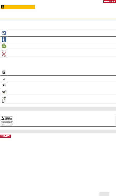
1.2.2Symbols in the documentation
The following symbols are used in this document:
Read the operating instructions before use.
Instructions for use and other useful information
Dealing with recyclable materials
Do not dispose of electric equipment and batteries as household waste
1.2.3Symbols in the illustrations
The following symbols are used in illustrations:
These numbers refer to the corresponding illustrations found at the beginning of these operating instructions
The numbering reflects the sequence of operations shown in the illustrations and may deviate from the steps described in the text
Item reference numbers are used in the overview illustrations and refer to the numbers used in the product overview section
This symbol is intended to draw special attention to certain points when handling the product.
Wireless data transfer
1.3 On the product Laser information
Laser class 2 based on standard IEC60825-1 / EN60825-1:2007 and compliant with CFR 21 § 1040 (Laser Notice 50).
Do not look straight into the laser beam.
1.4Product information
products are designed for professional users and only trained, authorized personnel are permitted to operate, service and maintain the products. This personnel must be specifically informed about the possible hazards. The product and its ancillary equipment can present hazards if used incorrectly by untrained personnel or if used not in accordance with the intended use.
The type designation and serial number are printed on the rating plate.
Write down the serial number in the table below. You will be required to state the product details when contacting Hilti Service or your local Hilti organization to inquire about the product.
Product information
|
Rotating laser | laser receiver |
PR 30-HVSG A12 | PRA 30G |
|
Generation |
02 |
|
Serial no. |
|
|
|
|
1.5 |
Declaration of conformity |
|
We declare, on our sole responsibility, that the product described here complies with the applicable directives and standards. A copy of the declaration of conformity can be found at the end of this documentation.
The technical documentation is filed here:
English 3
Printed: 07.05.2018 | Doc-Nr: PUB / 5376993 / 000 / 02

Hilti Entwicklungsgesellschaft mbH | Tool Certification | Hiltistrasse 6 | D-86916 Kaufering, Germany
1.6Type approval test
The notified tester, CSA Group Bayern, number 1948, has tested the devices and evaluated the documents and issued the following type approval certifications:
•PR 30HVSG A12: ZS 17 10 50140 006
•PRA 30G: ZS 17 10 50140 005
2Safety
2.1Basic information concerning safety
Read all safety instructions and other instructions. Failure to observe the safety instructions and other instructions may result in electric shock, fire and/or serious injury.
Retain all safety precautions and instructions for future reference. The term “electric tool” used in the safety instructions refers to your mains-operated (corded) electric tool or battery-operated (cordless) electric tool.
2.2General safety measures
Stay alert, watch what you are doing and use common sense when operating a power tool. Do not use a power tool while you are tired or under the influence of drugs, alcohol or medication. A moment of inattention while operating the power tool can result in serious personal injury.
Do not render safety devices ineffective and do not remove information and warning notices.
Keep children well away from laser devices.
Laser radiation in excess of Class 2 may be emitted if the device is opened without following the correct procedures. Have the device repaired only by Hilti Service.
Project laser beams well above or well below eye height.
Take the influences of the surrounding area into account. Do not use the device where there is a risk of fire or explosion.
Statement in accordance with FCC §15.21: Changes or modifications not expressly approved by Hilti can restrict the user’s authorization to operate the equipment.
You must check the accuracy of the device after it has been dropped or subjected to other mechanical stresses.
When the device is brought into a warm environment from very cold conditions, or vice-versa, allow it to become acclimatized before use.
When using adapters or accessories, make sure that the equipment is securely mounted.
Keep the laser aperture clean to avoid measurement errors.
The device is designed for the tough conditions of jobsite use, but as with other optical and electronic instruments (e.g. binoculars, spectacles, cameras) it must be handled with care.
The device is protected to prevent the ingress of moisture, but you must always wipe it dry before stowing it in the transport container.
Check the device before using it for important measuring work.
Repeatedly check accuracy while using the device.
Make sure that the workplace is well lit.
Do not expose the laser to rain or wet conditions.
Do not touch the contacts.
Maintain the device carefully. Check that moving parts are in full working order and do not jam and make sure there are no parts that are broken or damaged in such a way as to impair operation of the device. If it damaged, have the device repaired before use. Many accidents are caused by poorly maintained equipment.
2.3Proper preparation of the working area
Secure the area in which you will be taking measurements. Make sure that the laser beam is not directed toward other persons or toward yourself while setting up the laser tool.
Avoid unfavorable body positions when working from ladders. Make sure you work from a safe stance and stay in balance at all times.
Readings taken in the vicinity of reflective objects or surfaces, through panes of glass or similar materials may produce incorrect results.
4 English
Printed: 07.05.2018 | Doc-Nr: PUB / 5376993 / 000 / 02

Ensure that the tool is set up on a stable, level surface (not subject to vibration).
Use the tool only within its specified limits.
Use the tool and its accessories etc. in accordance with these instructions and in the manner intended for the particular type of tool. Take the working conditions and the work to be performed into account. Use of tools for applications different from those intended could result in a hazardous situation.
Use of the telescopic staff in the vicinity of overhead high voltage cables is not permissible.
2.4Electromagnetic compatibility
Although the tool complies with the strict requirements of the applicable directives, Hilti cannot exclude the following possibilities:
•The tool may be negatively affected by powerful electromagnetic radiation, possibly leading to incorrect operation.
In these cases, or if you are otherwise unsure, confirmatory measurements should be made by other means.
•The tool can cause interference to other devices (e.g. aircraft navigation equipment).
2.5Laser classification for Class 2 laser products
The tool complies with laser Class 2 as per IEC60825-1:2007 / EN60825-1:2007. This tool may be used without need for further protective measures.
CAUTION
Risk of injury! Do not direct the laser beam toward persons.
Never look directly into the source of the laser beam. In the event of direct eye contact, close your eyes and move your head out of the path of the laser beam.
2.6Careful use of battery-powered tools
Do not expose batteries to high temperatures, the direct heat of the sun, and keep them away from fire. There is a risk of explosion.
Do not disassemble, squash or incinerate batteries and do not subject them to temperatures over 80°C (176°F). This presents a risk of fire, explosion or injury through contact with caustic substances.
Do not subject the battery to hard mechanical impacts and do not throw the battery.
Batteries must be kept out of reach of children.
Avoid ingress of moisture. Ingress of moisture may cause a short circuit, resulting in burning injuries or fire.
Under abusive conditions, liquid may leak from the battery. Avoid contact with the liquid. If contact accidentally occurs, flush with water. If the liquid contacts the eyes, also seek medical attention.
Liquid leaking from the battery may cause irritation or burns.
Use only batteries of the type approved for use with the applicable tool. Use of other batteries or use of the batteries for purposes for which they are not intended presents a risk of fire and explosion.
Store the battery in a cool and dry place. Never store the battery where it is exposed to direct sunlight or sources of heat, e.g. on heaters / radiators or behind glass.
When not in use, keep the battery and the charger away from paper clips, coins, keys, nails, screws or other small metal objects that could cause a short circuit at the battery terminals or the charging contacts. Short-circuiting the contacts on a battery or charger may cause burning injuries or start a fire.
Do not charge or continue to use damaged batteries (e.g. batteries with cracks, broken parts, bent or pushed-in and/or pulled-out contacts).
Recharge only with the charger specified by the manufacturer. A charger that is suitable for a certain type of battery may present a risk of fire when used with other types of battery.
Observe the special guidelines applicable to the transport, storage and use of Li-ion batteries.
The battery must be insulated or removed from the tool before the tool is shipped or sent by mail.
Leaking batteries may damage the tool.
If the battery gets noticeably hot when not in use, this may indicate that the battery or the tool / battery system is faulty. In this case, place the tool in a non-flammable location, well away from flammable materials, where it can be kept under observation and allowed to cool down.
English 5
Printed: 07.05.2018 | Doc-Nr: PUB / 5376993 / 000 / 02

3Description
3.1Product overview
3.1.1PR 30-HVSG A12 rotating laser
@Laser beam (plane of rotation)
; |
Rotary head |
=Sight
6 English
%
&
(
Grip
Battery release button Liion battery
Printed: 07.05.2018 | Doc-Nr: PUB / 5376993 / 000 / 02
)
+
Battery state-of-charge display |
§ |
Base plate with 5/8" thread |
Control panel |
|
|
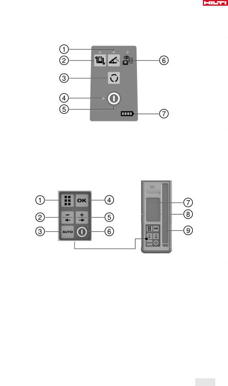
3.1.2PR 30-HVSG A12 control panel
@Inclined plane mode button and LED
;Shock warning function button and LED
=Speed of rotation button
%LED for status “On/off” and “Auto-leveling”
3.1.3PRA 30G laser receiver and control panel
@Menu button
;Decrease inclination, to the left. Move PRA 90 down. Navigation in menu.
=Automatic alignment / surveillance mode / marking function
%OK button
&
(
)
&
(
)
+
§
On/off button
Surveillance mode LED (only with automatic vertical alignment)
Battery charge status LED
Increase inclination, to the right. Move PRA 90 up. Navigation in menu. On/off button
Display Marking notch
Detection window
English 7
Printed: 07.05.2018 | Doc-Nr: PUB / 5376993 / 000 / 02

3.1.4PRA 30G laser receiver display
@Distance of the laser beam from the marking notch
;Volume indicator
=Indicator showing beam segments switched off or on
3.2Intended use
%
&
(
Battery status indicator Accuracy indicator
Position of the receiver relative to the height of the laser plane
The product described is a rotating laser with a visible rotating laser beam. It can be operated by one person. The tool is designed to be used to determine, transfer and check levels, verticals, slopes and right angles.
Use only the Hilti B 12⁄2.6 Li-Ion battery for this product.
Use only the Hilti C 4⁄1250 charger for this product.
3.3Auto-leveling
Auto-leveling takes place after the tool is switched on. LEDs indicate the current operating status. Auto-
leveling is active and can be deactivated by way of the button. The tool can be set up directly on the ground or floor, on a tripod, or with the aid of suitable mounting brackets.
3.4Automatic alignment
Automatic alignment allows a single person to bring the laser plane into alignment with the laser receiver. The rotating laser tool detects the applicable direction of alignment as follows:
•Horizontal in conjunction with the PRA 90 automatic tripod and PRA 30G laser receiver.
•Inclination in the X-axis in conjunction with the PRA 30G laser receiver.
•Vertical in conjunction with the PRA 30G laser receiver.
3.5Inclination
Inclination can be carried out manually or automatically. The PRA 79 slope adapter can be used for larger angles of inclination.
3.6Surveillance function
The rotating laser monitors alignment of the laser plane in conjunction with the PRA 30G laser receiver. In the event of an alignment deviation the system corrects the direction of the laser plane, keeping it at the zero point of the laser receiver. The rotating laser corrects all errors caused by temperature fluctuations, wind or other such influences. If the optical connection (line of sight) between the rotating laser and the laser receiver is interrupted for longer than two minutes, the system indicates an error. During vertical alignment, the surveillance function can be activated only via the AUTO menu.
3.7Automatic switch-off
The tool switches off automatically if it is unable to level itself because the rotating laser:
• Is inclined too greatly relative to the horizontal plane (except when in inclined plane mode).
8 English
Printed: 07.05.2018 | Doc-Nr: PUB / 5376993 / 000 / 02
•Is blocked mechanically.
•Has been knocked off level by an impact or vibration.
•Has identified a fault.
When the tool has switched itself off, rotation stops and all LEDs flash.
3.8Shock warning function
If the rotating laser is knocked off level during operation, the built-in shock warning function switches the tool to warning mode. The shock warning function does not go active until two minutes after completion of auto-leveling. If a button on the control panel is pressed within this two-minute period it will take a further two minutes for the shock warning function to go active. If the rotating laser is in warning mode:
•All LEDs flash.
•The laser stops rotating.
•The laser beam switches off.
The sensitivity of the shock warning function can be set using the PRA 30G laser receiver.
The shock warning function can be switched off by pressing the |
button if the ground or floor is not free |
|
from vibration or when you are working in inclined plane mode. |
|
|
Deactivate the shock warning function. → page 19 |
|
|
|
|
|
3.9 |
Sleep mode |
|
Sleep mode may be activated on the rotating laser during breaks between work or during other activities. All settings concerning the laser plane or inclination are retained while in this status. Sleep mode saves power and extends battery life.
PRA 30G the laser receiver is used to activate / deactivate sleep mode.
Sleep mode remains active for a maximum of 4 hours. The system switches itself off after this time.
3.10Switching off beam segments
Individual segments of the path of the laser beam can be deactivated in order to:
•Avoid exposing yourself or bystanders to the laser beam.
•Avoid influencing other measuring or alignment work being carried out in the vicinity.
3.11Laser receiver / remote control unit
Hilti laser receivers digitally indicate the distance between the marking notch on the laser receiver and the position at which the laser beam (laser plane) strikes the detection area on the receiver. The laser beam can also be received over long distances. The PRA 30G can be used as a laser receiver and also as a remote control unit for the rotating laser.
3.12Pairing accessories and device
Pairing accessories and device
Pairing is the act of enabling accessories and devices to communicate with each other by wireless.
The rotating laser and the laser receiver are already paired when supplied. This helps ensure trouble-free operation within the vicinity of other wireless devices.
Additional laser receivers or PRA 90 automatic tripods cannot be used without first being paired.
Pair the rotating laser and the laser receiver. → page 19
Pair the tripod and laser receiver. → page 19
3.13LED indicators
The rotating laser is equipped with LED indicators. |
|
|
|
|
|
|
|
Status |
Meaning |
|
|
All LEDs blink. |
• The tool has been bumped, knocked off level or |
||
|
has a fault. |
|
|
The auto-leveling LED flashes green. |
• The tool is in the leveling phase. |
|
|
|
|
|
9 |
|
|
English |
|
Printed: 07.05.2018 | Doc-Nr: PUB / 5376993 / 000 / 02
Loading...