


PS 250 / PS 200 S
Operating instructions |
en |
Mode d’emploi |
fr |
Manual de instrucciones |
es |
Manual de instruções |
pt |
Printed: 10.12.2013 | Doc-Nr: PUB / 5135501 / 000 / 01

1 |
|
|
|
|
|
|
|
|
|
|
|
|
|
|
|
|
|
|
|
|
|
|
|
|
|
|
|
|
|
|
|
|
|
|||||
|
|
|||||||||||
|
|
|
|
|
|
|
|
|
||||
|
|
|
|
|
|
|
|
|
|
|
|
|
|
|
|
|
|
|
|
|
|
|
|
|
|
Printed: 10.12.2013 | Doc-Nr: PUB / 5135501 / 000 / 01
2 |
3 |
4 |
Printed: 10.12.2013 | Doc-Nr: PUB / 5135501 / 000 / 01 |
ORIGINAL OPERATING INSTRUCTIONS
PS 250 ferroscan system
PS 200 S ferroscan
en
It is essential that the operating instructions are read before the tool is operated for the first time.
Always keep these operating instructions together with the tool.
Ensure that the operating instructions are with the tool when it is given to other persons.
Contents |
Page |
|
1 |
General information |
1 |
2 |
Description |
2 |
3 |
Items supplied, accessories, spare parts |
3 |
4 |
Technical data |
7 |
5 |
Safety instructions |
10 |
6 |
Before use |
11 |
7 |
Operation |
11 |
8 |
Care and maintenance |
28 |
9 |
Troubleshooting |
29 |
10 |
Disposal |
31 |
11 |
Manufacturer’s warranty |
32 |
12 |
FCC statement / IC statement |
32 |
1 These numbers refer to the corresponding illustrations. The illustrations can be found on the fold-out cover pages. Keep these pages open while studying the operating instructions.
In these operating instructions, the designation “the tool” always refers to PS 200 S Ferroscan. The designation “PS 250 Ferroscan system” applies to the whole system consistingofthePS200Sscanner, PSA100monitorand PROFIS Ferroscan PC software for data evaluation. The designation “PS 200 S Ferroscan”, on the other hand, applies only to the scanner.
Components 1
@ PS 200 S scanner ; PSA 60 soft pouch = PSA 100 monitor
% PSA 55 infrared adapter & PSA 63 hand strap
( PSA 92 USB data cable
) PUA 95 Micro USB data cable + PSA 93 headset with microphone § PSA 64 soft pouch
/ PSA 62 carrying strap : PSA 80 battery pack · PSA 82 battery pack $ PUA 81 AC adapter £ PUA 80 charger
| Supply cord
¡ PSA 10/11 reference grid set Q PUA 90 adhesive tape
W Folding rule
E PSA 70 brush
R PUA 70 marking pen set
T PROFIS Ferroscan software
Z PS 250 toolbox
1 General information
1.1 Safety notices and their meaning
DANGER
Draws attention to imminent danger that will lead to serious bodily injury or fatality.
WARNING
Draws attention to a potentially dangerous situation that could lead to serious personal injury or fatality.
CAUTION
Draws attention to a potentially dangerous situation that could lead to slight personal injury or damage to the equipment or other property.
NOTE
Draws attention to an instruction or other useful information.
1.2Explanation of the pictograms and other information
Warning signs
General |
Warning: |
Warning: |
warning |
electricity |
caustic |
|
|
substances |
1

Symbols
|
Read the |
Return waste |
|
en |
|||
operating |
material for |
||
|
instructions |
recycling. |
|
|
before use. |
|
Location of identification data on the tool
The type designation and serial number can be found on the type identification plate on the tool. Make a note of this data in your operating instructions and always refer to it when making an enquiry to your Hilti representative or service department.
Type:
Generation: 02
Serial no.:
2 Description
2.1 Use of the product as directed
The tool is intended to be used for locating reinforcing bars in concrete, measuring depth of concrete cover and estimating the diameter of the bars in the uppermost layer in accordance with the specifications detailed in the technical data provided in these operating instructions.
The tool is designed for professional use and may be operated, serviced and maintained only by trained, authorized personnel. This personnel must be informed of any special hazards that maybe encountered. The tool and its ancillary equipment may present hazards when used incorrectly by untrained personnel or when used not as directed.
Observe the information printed in the operating instructions concerning operation, care and maintenance.
Take the influences of the surrounding area into account. Do not use the tool or appliance where there is a risk of fire or explosion.
Modification of the tool or tampering with its parts is not permissible.
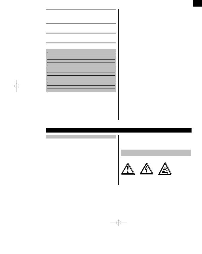
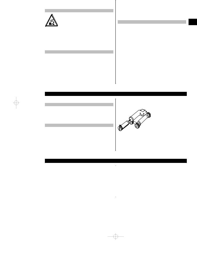
2.2 PSA 55 infrared adapter
The PSA 55 infrared adapter is used to store scans before they are subsequently transferred to a computer. The adapter has a storage capacity of approx. 100 scans.
2.3 Applications
The tool can be used for various non-destructive detection applications on steel-reinforced concrete structures (e.g. locating reinforcing bars in the uppermost layers, measuring depth of concrete cover and estimating the diameter of the bars detected). The scanning mode used depends on the application. These fall broadly into the following categories:
Application |
Scanning mode |
|
|
Avoiding damage to reinforcing bars when drilling or core drilling |
Quickscan detection, Imagescan or |
|
Blockscan |
Determining the position / number and diameter of bars for load- |
Imagescan |
bearing capacity checks or depth of cover measurements |
|
Determining depth of concrete cover over large areas |
Quickscan recording |
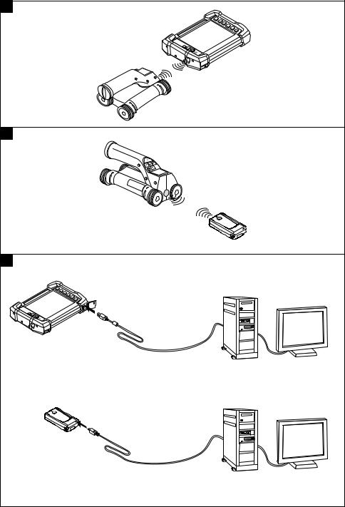
2.4 Using the system
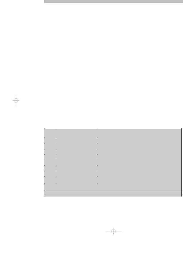
The system functions by running the scanner directly over the surface of the structure. The data collected is stored in the scanner until it can be transferred to the monitor. The monitor is used for storing large amounts of data and for viewing the scans. It can also be used for on-the-spot evaluation of scans. The data can also be downloaded to a PC. The PC software offers advanced evaluation options, data archiving functions and the ability to quickly print out complete reports.
2.5 Quickscan detection
The scanner is moved across the surface at right angles to the reinforcing bars. The position and approximate depth of the reinforcing bars can be determined and marked right away on the surface of the concrete.
2
2.6 Quickscan detection with accurate depth measurement
Before scanning, the operator is required to enter values for the diameter of the reinforcing bars and the spacing between the bars. The scan is then carried out as described for Quickscan detection.
|
|
|
|
|
|
|
2.7 Quickscan recording |
|
|
|
|
||
Data is recorded automatically as the scanner is moved over the surface of the concrete. This data is subsequently |
|
|||||
en |
||||||
transferred to the monitor where it can be evaluated and the average depth of cover determined. If the data is |
||||||
downloaded to a PC, the information can be evaluated, archived and a report printed. Further evaluation options |
|
|||||
allow Quickscan recordings to be imported and evaluated automatically, statistical evaluations prepared and scans |
|
|||||
displayed in the form of large-area evaluations. |
|
|||||
|
|
|
|
|
|
|
2.8 Imagescan |
|
|
|
|
||
A reference grid is attached at the area of interest using the adhesive tape supplied. After selecting the Imagescan |
|
|||||
mode with the scanner, the rows and columns of the grid are scanned following the instructions on the screen. The |
|
|||||
data is transferred to the monitor where the image can be viewed and evaluated. The position of the reinforcing bars |
|
|||||
relative to the concrete surface is indicated. Bar diameter can be estimated and bar depth determined. If the data is |
|
|||||
downloaded to the PC application, this information can be evaluated as on the monitor, with the additional advantage |
|
|||||
of allowing a series of points to be recorded along with associated depth and diameter, and the data saved for |
|
|||||
future use. Reports can also be printed. Further evaluation options allow Imagescans to be imported and evaluated |
|
|||||
automatically, statistical evaluations prepared and scans displayed in the form of large-area evaluations. |
|
|||||
|
|
|
|
|
|
|
2.9 Blockscan |
|
|
|
|
||
A reference grid is attached at the area of interest using the adhesive tape supplied. After selecting Blockscan mode, |
|
|||||
the user is prompted to select the first area to scan. An Imagescan is then made. After completing the Imagescan, the |
|
|||||
user is prompted to select the next area to scan. This should be adjacent to the previous area. Attach the grid and then |
|
|||||
scan as before. This procedure can be repeated for up to 3 x 3 Imagescans. The data is transferred to the monitor. The |
|
|||||
Imagescans are automatically stitched together to form a larger image. The reinforcement layout can then be viewed |
|
|||||
over the whole area. Individual Imagescans can be selected for evaluation by “zooming in”. If the data is downloaded |
|
|||||
to the PC application, this information can be evaluated as on the monitor, with the additional advantage of allowing a |
|
|||||
series of points to be recorded along with associated depth and diameter, and the data saved for future use. Reports |
|
|||||
can also be printed. |
|
|
|
|
||
|
|
|
|
|
|
|
3 Items supplied, accessories, spare parts |
|
|
||||
|
|
|
|
|
|
|
3.1 Items supplied |
|
|
|
|
||
|
|
|
|
|
|
|
3.1.1 PS 250 Ferroscan system |
|
|
|
|
||
|
|
|
|
|
||
Num- |
Designation |
Comments |
|
|||
ber |
|
|
|
|
|
|
1 |
PS 200 S scanner 1 |
|
|
|
|
|
1 |
PSA 60 soft pouch |
Soft pouch for the PS 200 S scanner |
|
|
||
|
|
|
|
|
|
|
1 |
PSA 100 monitor1 |
|
|
|
|
|
1 |
PSA 64 soft pouch |
Soft pouch for the PSA 100 monitor |
|
|
||
|
|
|
|
|
||
1 |
PSA 63 hand strap |
For the PS 200 S scanner |
|
|||
|
|
|
|
|
||
1 |
PSA 55 infrared adapter |
For temporary storage of data from the PS 200 S scanner |
|
|||
|
|
|
|
|
||
1 |
PUA 95 Micro USB data cable |
Data cable for connecting the PSA 55 infrared adapter to a PC |
|
|||
|
|
|
|
|
||
1 |
PSA 97 data module |
Contains the operating instructions in electronic form and is used to |
|
|||
|
|
update the PSA 100 monitor |
|
|
||
1 Version depends on the country-specific version of the system ordered.
2 May or may not be included in the items supplied, depending on the country-specific version of the system ordered.
3

|
|
Num- |
Designation |
Comments |
|
|
ber |
|
|
|
|
|
|
|
|
|
1 |
PSA 92 USB data cable |
PSA 100 monitor to PC |
|
|
|
|
|
|
|
1 |
PSA 93 headset with micro- |
For the PSA 100 monitor |
en |
|
|
phone |
|
|
2 |
AA-size alkaline batteries |
For the PSA 55 infrared adapter |
|
|
|
|
|
|
|
|
1 |
PSA 80 battery pack |
NiMH battery pack for the PS 200 S scanner |
|
|
|
|
|
|
|
1 |
PUA 80 charger |
Charger for the PSA 80 battery pack |
|
|
|
|
|
|
|
1 |
Supply cord1 |
Supply cord for the PUA 80 charger |
|
|
1 |
PSA 82 battery pack |
Li-ion battery pack for the PSA 100 monitor |
|
|
|
|
|
|
|
1 |
PUA 81 AC adapter |
AC adapter for charging the PSA 100 monitor |
|
|
|
|
|
|
|
1 |
PSA 75 brush |
For removing dust and particles of concrete before applying |
|
|
|
|
PUA 90 adhesive tape |
|
|
1 |
Cleaning cloth |
|
|
|
|
|
|
|
|
1 |
Folding rule2 |
|
|
|
5 |
PSA 10/11 reference grid1 |
For making an Imagescan |
|
|
1 |
PUA 90 adhesive tape |
For attaching the reference grid to a dry, dust-free concrete surface |
|
|
|
|
|
|
|
1 |
PUA 70 marking pen set |
Set of 6 red and 6 black marking pens for marking the grid position |
|
|
|
|
and object position |
|
|
1 |
PROFIS Ferroscan software |
PC software on CD-ROM for the PS 250 Ferroscan system / |
|
|
|
|
PS 200 S Ferroscan set |
|
|
1 |
PSA/PUA operating instruc- |
|
|
|
|
tions |
|
|
|
1 |
PSA 100 operating instructions |
|
|
|
|
|
|
|
|
1 |
PS 200 S Ferroscan / PS 250 |
|
|
|
|
Ferroscan system operating |
|
|
|
|
instructions |
|
|
|
1 |
PS 200 S manufacturer’s cer- |
|
|
|
|
tificate |
|
|
|
1 |
PSA 100 manufacturer’s certifi- |
|
|
|
|
cate |
|
|
|
1 |
PS 250 toolbox |
Plastic toolbox with insert for the PS 250 Ferroscan system |
|
|
|
|
|
|
|
1 Version depends on the country-specific version of the system ordered. |
||
|
|
2 May or may not be included in the items supplied, depending on the country-specific version of the system ordered. |
||
3.1.2 PS 200 S Ferroscan set
Num- |
Designation |
Comments |
|
ber |
|
|
|
|
|
|
|
1 |
PS 200 S scanner 1 |
|
|
1 |
PSA 55 infrared adapter |
For temporary storage of data from the PS 200 S scanner |
|
|
|
|
|
1 |
PSA 60 soft pouch |
Soft pouch for the PS 200 S scanner |
|
|
|
|
|
1 |
Version depends on the country-specific version of the system ordered. |
||
|
|
||
2 |
May or may not be included in the items supplied, depending on the country-specific version of the system ordered. |
||
|
|
|
|
4

Num- |
Designation |
Comments |
|
|
|
ber |
|
|
|
|
|
|
|
|
|
|
|
1 |
PSA 62 carrying strap |
|
|
|
|
|
|
|
|
|
|
1 |
PSA 63 hand strap |
Soft pouch for the PS 200 S scanner |
|
|
|
|
|
|
|
|
en |
2 |
AA-size alkaline batteries |
|
|
||
|
|
|
|
|
|
1 |
PSA 80 battery pack |
NiMH battery pack for the PS 200 S scanner |
|
|
|
|
|
|
|
|
|
1 |
PUA 80 charger |
Charger for the PSA 80 battery pack |
|
|
|
|
|
|
|
|
|
1 |
PUA 95 Micro USB data cable |
Data cable for connecting the PSA 55 infrared adapter to a PC |
|
|
|
|
|
|
|
|
|
5 |
PSA 10/11 reference grid1 |
For making an Imagescan |
|
|
|
1 |
PUA 90 adhesive tape |
For attaching the reference grid to a dry, dust-free concrete surface |
|
|
|
|
|
|
|
|
|
1 |
PUA 70 marking pen set |
Set of 6 red and 6 black marking pens for marking the grid position |
|
|
|
|
|
and object position |
|
|
|
1 |
PROFIS Ferroscan software |
PC software on CD-ROM for the PS 250 Ferroscan system / |
|
|
|
|
|
PS 200 S Ferroscan set |
|
|
|
1 |
PSA/PUA operating instruc- |
|
|
|
|
|
tions |
|
|
|
|
1 |
PS 200 S Ferroscan / PS 250 |
|
|
|
|
|
Ferroscan system operating |
|
|
|
|
|
instructions |
|
|
|
|
1 |
PSA 75 brush |
For removing dust and particles of concrete before applying |
|
|
|
|
|
PUA 90 adhesive tape |
|
|
|
1 |
Folding rule2 |
|
|
|
|
1 |
Cleaning cloth |
|
|
|
|
|
|
|
|
|
|
1 |
PS 200 S toolbox |
Plastic toolbox with insert |
|
|
|
|
|
|
|
|
|
1 |
PS 200 S manufacturer’s cer- |
|
|
|
|
|
tificate |
|
|
|
|
1 Version depends on the country-specific version of the system ordered. |
|
|
|
||
2 May or may not be included in the items supplied, depending on the country-specific version of the system ordered. |
|
|
|
||
|
|
|
|
|
|
3.1.3 PS 200 S scanner |
|
|
|
|
|
|
|
|
|
||
Num- |
Designation |
Comments |
|
|
|
ber |
|
|
|
|
|
1 |
PS 200 S scanner 1 |
|
|
|
|
1 |
PSA 60 soft pouch |
Soft pouch for the PS 200 S scanner |
|
|
|
|
|
|
|
|
|
1 |
PSA 80 battery pack |
NiMH battery pack for the PS 200 S scanner |
|
|
|
|
|
|
|
|
|
1 |
PSA 63 hand strap |
For the PS 200 S scanner |
|
|
|
|
|
|
|
|
|
1 |
PSA/PUA operating instruc- |
|
|
|
|
|
tions |
|
|
|
|
1 |
PS 200 S Ferroscan / PS 250 |
|
|
|
|
|
Ferroscan system operating |
|
|
|
|
|
instructions |
|
|
|
|
1 |
PS 200 S manufacturer’s cer- |
|
|
|
|
|
tificate |
|
|
|
|
1 Version depends on the country-specific version of the system ordered. |
|
|
|
||
5

3.2 Accessories and spare parts
|
|
Item no. |
Designation |
Comments |
|
|
|
|
|
|
|
2006082 |
PSA 100 monitor |
PSA 100 monitor, PSA 82 battery pack, PUA 92 USB data |
|
|
|
|
cable, PSA 97 data module, manufacturer’s certificate, oper- |
|
|
|
|
ating instructions, packed in a cardboard box |
en |
|
|
|
|
|
377654 |
PSA 10 reference grid |
Reference grid in mm (in packs of 5) |
|
|
|
|
|
|
|
|
377655 |
PSA 11 reference grid |
Reference grid in inches (in packs of 5) |
|
|
|
|
|
|
|
319362 |
PUA 90 adhesive tape |
For attaching the reference grid to a dry, dust-free concrete |
|
|
|
|
surface |
|
|
340806 |
PUA 70 marking pen set |
For marking the grid position and object position (12 pens) |
|
|
|
|
|
|
|
305144 |
PSA 63 hand strap |
For the PS 200 S scanner |
|
|
|
|
|
|
|
377657 |
PSA 60 soft pouch |
For the PS 200 S scanner |
|
|
|
|
|
|
|
2006088 |
PSA 64 soft pouch |
For the PSA 100 monitor |
|
|
|
|
|
|
|
319412 |
PSA 62 shoulder strap |
For carrying the PS 200 S scanner |
|
|
|
|
|
|
|
2004459 |
PUA 81 AC adapter |
For charging the PSA 100 monitor |
|
|
|
|
|
|
|
1 |
PUA 80 charger |
For charging the PSA 80 battery pack, incl. supply cord |
|
|
|
|
|
|
|
2006180 |
PUA 82 motor vehicle power |
AC adapter for charging the PSA 100 monitor |
|
|
|
adapter |
|
|
|
377472 |
PSA 80 battery pack |
For the PS 200 S scanner |
|
|
|
|
|
|
|
416930 |
PSA 82 battery pack |
For the PSA 100 monitor |
|
|
|
|
|
|
|
2006183 |
PSA 85 charger |
Charger for the PSA 82 battery pack |
|
|
|
|
|
|
|
2013775 |
PSA 92 USB data cable |
For transferring data from the PSA 100 monitor to a PC |
|
|
|
|
|
|
|
2031976 |
For data transfer from the |
PSA 55 infrared adapter for PC |
|
|
|
PUA 95 Micro USB data cable |
|
|
|
305143 |
PSA 93 headset |
For the PSA 100 monitor |
|
|
|
|
|
|
|
2006187 |
PSA 55 infrared adapter |
For temporary storage of data from the PS 200 S scanner |
|
|
|
|
|
|
|
2006191 |
PSA 97 data module |
Contains the operating instructions in electronic form and is |
|
|
|
|
used to update the PSA 100 monitor |
|
|
2006200 |
PSA 65 carrying device |
For the PSA 100 monitor |
|
|
|
|
|
|
|
319416 |
Hilti PROFIS Ferroscan PC soft- |
PC software on CD-ROM for the PS 250 Ferroscan system / |
|
|
|
ware |
PS 200 S scanner set |
|
|
2031824 |
Hilti toolbox for PS 250 |
|
|
|
|
|
|
|
|
2044483 |
Hilti toolbox for PS 200 S |
|
|
|
|
|
|
|
|
2013776 |
PSA 75 brush |
For removing dust and particles of concrete before applying |
|
|
|
|
PUA 90 adhesive tape |
|
|
276946 |
Folding rule |
|
|
|
|
|
|
|
|
2005011 |
Cleaning cloth |
|
|
|
|
|
|
|
|
2004955 |
PSA/PUA P1 operating instruc- |
For Europe / Asia |
|
|
|
tions |
|
|
|
2012529 |
PSA/PUA P2 operating instruc- |
For USA / Canada |
|
|
|
tions |
|
|
|
2004954 |
PSA 100 P1 operating instruc- |
For Europe / Asia |
|
|
|
tions |
|
6
Item no. |
Designation |
Comments |
|
|
|
2004815 |
PSA 100 P2 operating instruc- |
For USA / Canada |
|
tions |
|
2037330 |
PS 200 S Ferroscan / PS 250 |
For Europe / Asia |
|
Ferroscan system P1 operating |
|
|
instructions |
|
2037331 |
PS 200 S Ferroscan / PS 250 |
For USA / Canada |
|
Ferroscan system P2 operating |
|
|
instructions |
|
en
4 Technical data
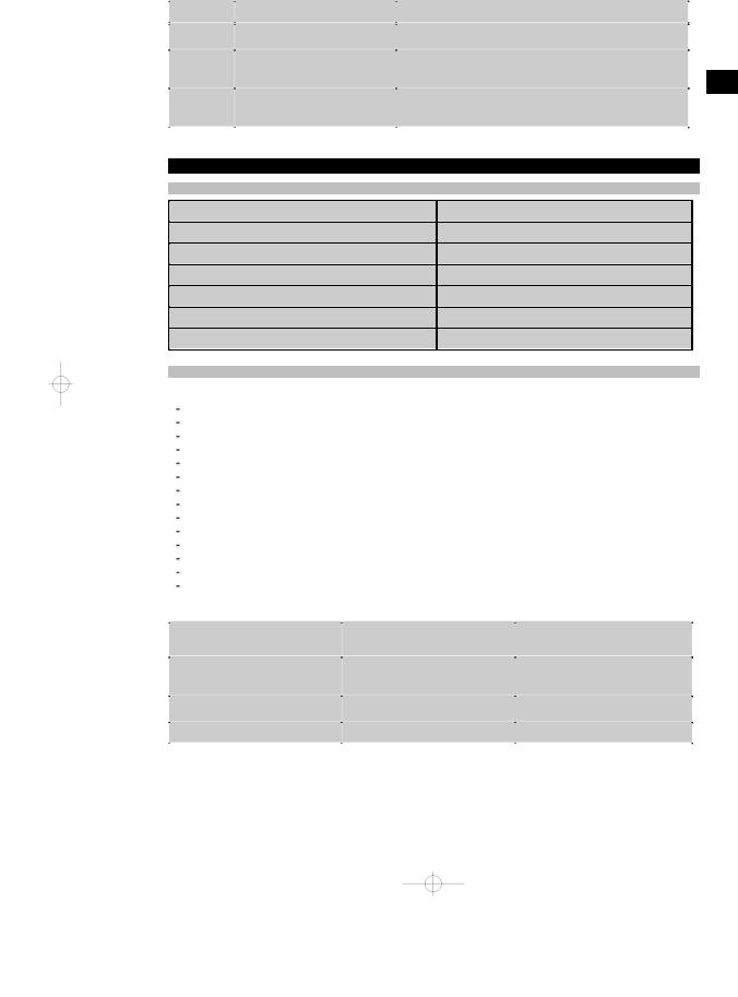
4.1 Ambient conditions
Operating temperature range |
-10…+50°C (+14…+122 °F) |
Storage temperature |
-20…+60°C (−4…+140 °F) |
Relative humidity (operation) |
Max. 90%, no condensation |
Dust and water protection (operation) |
IP54 |
Impact resistance (tool in toolbox) |
EN 60068-2-29 |
Dropping |
EN 60068-2-32 |
Vibration (not in operation) |
MIL-STD 810 D |
4.2 System scanning performance
For reliable scanning results, the following conditions must be fulfilled:
Concrete surface smooth and flat. Reinforcement not corroded.
Reinforcement lying parallel to concrete surface.
Concrete does not contain additives or components with magnetic properties. Reinforcing bars lying within ± 5° of right angle to the scanning direction. Reinforcing bars are not welded.
Neighboring bars are of similar diameter. Neighboring bars are at a similar depth.
Accuracy specifications are valid only for the first layer of reinforcement.
No interfering influences from external magnetic fields or objects nearby with magnetic properties. Bars have relative magnetic permeability of 85–105.
The scanner wheels are clean and free from sand and grit etc.
All 4 scanner wheels are in contact and rotate when the scanner is moved across the object to be scanned. The bars comply with one of the following standards (depending on system item no.):
Standards for steel reinforcing bars
Item no. |
Standard |
Origin / applicability of the stan- |
|
|
dard |
|
|
|
2044434, 2044439, 2044473, |
DIN 488 |
European Union and all other coun- |
2044435, 2044472, 377646, |
|
tries not listed below |
377652 |
|
|
2044436, 2044474, 377649 |
ASTM A 615 / A 615M 01b |
United States of America, Taiwan, |
|
|
Latin America and Central America |
2044437, 2044475, 377650 |
CAN/CSA-G30, 18-M92 |
Canada |
|
|
|
7
|
|
Item no. |
Standard |
Origin / applicability of the stan- |
|
|
|
|
dard |
|
|
|
|
|
|
|
2044438, 2044470, 2044476, |
JIS G 3112 |
Japan, Korea |
|
|
2044478, 377651 |
|
|
|
|
2044471, 2044479, 408056 |
GB 50010-2002 |
China |
en |
|
|||
|
|
|
|
|
2078650, 2078660, 2078670 |
GOST 5781-82 |
Russia |
||
|
|
|
|
|
|
|
2078651, 2078661, 2078671 |
BIS 1786:1985 |
India |
|
|
|
|
|
4.3 Detection range, measurement range and accuracy
NOTE
If one or more of the specified conditions are not fulfilled, accuracy and precision may be compromised. The ratio of bar spacing to depth of cover (s:c) is often a limiting factor in resolving individual bars.
This is defined as:
F 
;
V
cDepth of cover
sSpacing
XSurface
In order to be able to resolve and locate individual bars, the ratio of bar spacing (s) to depth of cover (c) must be at least 2:1. Minimum bar spacing is 36 mm (1.4"). The higher of the two values applies when resolving individual bars. A depth of at least c 10 mm (0.4") is required in order to carry out a depth measurement.
NOTE
Placeasheetofnon-metallicmaterial(e.gcardboard, wood, polystyrenefoam,...) betweenthescannerand thesurface to be scanned if the minimum depth cannot be adhered to.
The starting point and finishing point of the scan (e.g. from the edge of the reference grid) must be at least 30 mm (1.2") away from the nearest reinforcing bar.
In the annex of these operating instructions you will find bar diameter tables in accordance with:
DIN 488
ASTM
CAN
JIS
GB 500110-2002
GOST 5781-82
BIS 1786:1985
Explanation of the bar diameter tables in the annex
[mm] Bar diameter in mm
Bar diameter
[in] |
Depth in inches |
[mm] |
Depth in mm |
0 |
Bar is visible at this depth but no depth is calculated. |
X |
Bar cannot be detected at this depth. |
8

The value indicates the typical accuracy of the depth measurement (deviation from actual) in mm or, respectively, in inches.
4.3.1Imagescan and Blockscan: Rebar diameter is known
Please refer to the bar diameter tables in the annex (1.).
4.3.2Imagescan and Blockscan: Rebar diameter is not known
Please refer to the bar diameter tables in the annex (2.).
4.3.3Quickscan recording: Rebar diameter is known
en
Please refer to the bar diameter tables in the annex (3.).
4.3.4Quickscan detection with depth measurement: Rebar diameter is known
Please refer to the bar diameter tables in the annex (4.).
4.3.5Quickscan detection
Depth measurement is accurate to within ±10% of the effective depth.
4.3.6Accuracy of bar diameter measurement
±1 standard diameter when rebar spacing : depth of cover ≥ 2 : 1. Bar diameter measurement is possible only at depths of up to 60 mm (2.4").
4.3.7Reinforcing bar location accuracy
Bar center locating accuracy (all modes): Typically ± 3 mm (0.12") relative to the measured position, when the ratio of bar spacing : depth of cover is ≥ 1.5:1.
4.4 Technical data for PS 200 S scanner
|
|
Maximum scanning speed |
0.5 m/sec (1.64 ft/s) |
|
|
Memory type |
Built-in flash memory for data |
|
|
Memory capacity |
9 Imagescans plus up to 30 m (98 ft) of recorded |
|
Quickscan (max. 10 scans) |
Screen type / size |
LCD / 50 × 37 mm (2" x 1.5") |
|
|
Screen resolution |
128 × 64 pixels |
|
|
Dimensions |
260 × 132 × 132 mm (10.2 x 5.2 x 5.2") |
|
|
Weight (with PSA 80 battery pack) |
1.4 kg (3.09 lb) |
|
|
Minimum battery life (with PSA 80 battery pack) |
8 hours under typical conditions |
|
|
Automatic power-off |
5 min. after last press of a button |
|
|
Backup battery type / life |
Lithium / 10 years (typically) |
|
|
Scanner-monitor data interface |
Infrared |
|
|
Scanner-monitor data transfer time |
16 s for 9 images, 2 s for 1 image |
|
|
Infrared range |
Typically 0.3 m (1 ft) |
|
|
Infrared output power |
Max. 500 mW |
|
|
|
|
4.5 Technical data for PSA 55 infrared adapter |
|
|
|
Battery |
1 x 1.5 V AAA |
|
|
Dimensions |
90 x 50 x 28 mm (3.5 x 2 x 1.1") |
|
|
Weight |
65 g (0.14 lb) |
|
|
9
Scanner - adapter data interface |
IrDa |
Adapter - computer data interface |
USB |
en 
 5 Safety instructions
In addition to the information relevant to safety given |
h) Makesurethatthetoolboxisproperlysecuredduring |
|
ineachofthesectionsoftheseoperatinginstructions, |
transport and does not present a risk of injury. |
|
the following points must be strictly observed at all |
|
|
times. |
|
|
5.3 Electromagnetic compatibility |
||
|
|
Although the tool complies with the strict requirements of |
5.1 Intended use |
|
the applicable directives, Hilti cannot entirely rule out the |
|
|
|
a)The tool and its ancillary equipment may present possibility of interference to the tool caused by powerful
|
hazards when used incorrectly by untrained per- |
electromagnetic radiation, leading to incorrect operation. |
|||
b) |
sonnel or when used not as directed. |
Accuracy must be checked by taking measurements by |
|||
To avoid the risk of injury, use only genuine Hilti |
other means when working under such conditions or |
||||
c) |
accessories and additional equipment. |
if you are unsure. Likewise, Hilti cannot rule out the |
|||
Modificationofthetoolortamperingwithitsparts |
possibility of interference with other devices (e.g. aircraft |
||||
d) |
is not permissible. |
navigation equipment). |
|||
Observe the information printed in the operat- |
|
|
|||
|
ing instructions concerning operation, care and |
|
|||
|
5.4 General safety precautions |
||||
|
maintenance. |
|
|
||
|
5.4.1 Mechanical safety precautions |
||||
e) |
Do not render safety devices ineffective and do |
||||
a) |
Check the tool for damage before use. If the tool |
||||
f) |
not remove information and warning notices. |
||||
Check the condition of the tool before use. If the |
|
is found to be damaged, have it repaired at a Hilti |
|||
|
tool is found to be damaged, have it repaired at a |
b) |
Service Center. |
||
g) |
Hilti Service Center. |
You must check the accuracy of the tool after it |
|||
Inparticularlycritical situationswheremeasurements |
|
has been dropped or subjected to other mechan- |
|||
|
have safety and structural stability implications, al- |
c) |
ical stresses. |
||
|
ways check results by removing material from the |
Whenthetoolisbrought intoawarmenvironment |
|||
|
surface of the structure and physically checking the |
|
from very cold conditions, or vice-versa, allow it |
||
|
position, depth and diameter of reinforcement at key |
d) |
to become acclimatized before use. |
||
h) |
positions. |
Although the tool is protected against the entry of |
|||
When drilling at or near to a bar indicated by the sys- |
|
moisture, it should be wiped dry before being put |
|||
|
tem, never drill deeper than the bar depth indicated. |
|
away in its transport container. |
||
|
|
|
|
||
|
|
|
5.4.2 Electrical safety precautions |
||
5.2 Proper organization of the workplace |
|
||||
|
a) |
Avoidshortcircuitingthebatteryterminals.Check |
|||
|
|
|
|||
|
|
|
|
that the terminals on the battery pack and in the tool |
|
|
|
|
|
are free from foreign objects before inserting the |
|
|
|
|
|
battery pack. Short circuiting the battery terminals |
|
|
|
|
|
presents a risk of fire, explosion and chemical burns. |
|
a) |
Keep the workplace tidy. Objects which could |
b) |
Make sure that the outer surfaces of the battery |
||
|
cause injury should be removed from the work- |
|
pack are clean and dry before inserting it in the |
||
|
|
charger. Observe the operating instructions for |
|||
|
ing area. Untidiness at the workplace can lead to |
|
|||
|
|
the charger. |
|||
|
accidents. |
|
|||
b) |
c) |
Useonlythebatterypackspecifiedintheseoperating |
|||
Keep other persons, especially children, away |
|||||
|
from the area in which the work is being carried |
d) |
instructions. |
||
|
Batteries that have reached the end of their life must |
||||
|
out. |
|
be disposed of safely and correctly to avoid environ- |
||
c) |
Wear non-skid shoes. |
|
|||
|
mental pollution. |
||||
d) |
Avoid unfavorable body positions when working |
e) |
|||
Remove the battery pack before transporting the tool |
|||||
|
from ladders. Make sure you work from a safe |
|
or storing it for a long period of time. Inspect the |
||
|
stance and stay in balance at all times. |
|
|||
|
|
battery pack for any signs of leakage or damage |
|||
e) |
Only use the tool within the defined limits. |
|
|||
|
before reusing it. |
||||
f) |
Check with a qualified person that it is safe to drill at |
f) |
|||
To avoid pollution of the environment, the tool |
|||||
|
a specified point before beginning drilling. |
|
must be disposed of in accordance with the cur- |
||
g) |
Do not use the tool where there is a risk of fire or |
|
|||
|
|
||||
|
explosion. |
|
|
||
10
rently applicable national regulations. Consult the manufacturerifyouareunsureofhowtoproceed.
5.4.3 Liquids
Caustic liquids may leak from defective batteries. Avoid contact with these liquids. In case of skin contact, wash the area affected with soap and plenty of water. In case of eye contact, rinse the eyesimmediately with water and subsequently consult a doctor.
5.5Requirements to be met by users
a)The tool may be operated, serviced and repaired only by authorized, trained personnel. This personnel must be informed of any special hazards that may be encountered.
b)Concentrate on your work. Stay alert. Pay attention to what you are doing. Approach the work with common sense. Do not use the tool if you are not concentrating.
c)Do not use the tool if it is defective.
d)If you are unsure of the scan results, consult a Hilti specialist before proceeding.
e)Observe all warning and information messages displayed by the scanner and monitor.
5.6 Scanning requirements and limitations |
en |
a)Always check the accuracy of the tool before commencing work on structures where measurements havesafetyand structural stabilityimplications. Scan a reinforcing bar of known location, depth and diameter and check the results against the accuracy specifications.
b)Do not use the PS 200 S scanner if the wheels do not turn freely or appear to be worn. Contact Hilti for repair information. The wheels may also be cleaned or replaced by the user.
c)Always check how the tool is configured before using it.
d)Applyonlylightpressuretothescannerwhenmoving it across the surface.
e)Reinforcement that lies beneath the uppermost layer of reinforcement may not be detected.
f)Remove all metal items of jewelry such as rings, pendants, bracelets, etc. before commencing scanning.
6 Before use
6.1 Charging the battery pack
Use the PUA 80 charger to charge the PSA 80 battery pack. Full instructions are contained in the charger operating instructions. The battery pack must be charged for 14 hours before first use.
6.1.1 Inserting and removing the battery pack
CAUTION
The battery pack must slide easily into the scanner. Do not use force when inserting the battery pack into the scanner as this may damage the battery pack and/or the scanner.
Check that the battery pack is correctly aligned with the scanner. When the battery pack end cap is facing you, the large groove in the battery pack must be on the left.
Push the battery pack into the opening as far as it will go. Turn the end cap clockwise until it clicks into place.
To remove the battery pack, turn the end cap anticlockwise as far as it will go. Pull the battery pack out of the scanner.
7 Operation
|
|
The scanner can be used without the monitor for scan- |
|
|
|
||
|
|
ning, or the monitor can be carried in the PSA 64 soft |
|
7.1 Carrying and using the system |
|
||
|
pouch. The first option is advantageous when working |
||
CAUTION |
|||
in areas that are difficult to access and maximum mo- |
|||
The temperature inside a motor vehicle exposed to the |
|||
bility is required, such as on a scaffold or ladder. When |
|||
heat of the sun can easily exceed the maximum permis- |
scanner memory is full (9 Imagescans made, 1 complete |
||
sible storage temperature for the PS 250 Ferroscan sys- |
Blockscan or 30 mm (98 ft) of Quickscan have been |
||
tem. Some of the components of the PS 250 Ferroscan |
recorded) the data can be transferred to the PSA 55 |
||
system may suffer damage if exposed to temperatures |
infrared adapter or the PSA 100 monitor. The monitor |
||
exceeding 60°C (140°F). |
|
||
11
can be kept nearby (e.g. at the foot of the scaffold, in a |
|
in its memory and wishes to avoid repeated journeys to |
|
||
vehicle, in the site office etc.). When the user intends to |
|
the monitor, the PSA 55 infrared adapter can be used |
make more scans than the scanner is capable of storing |
|
or the monitor attached to a belt or carried using the |
|
|
shoulder strap supplied. |
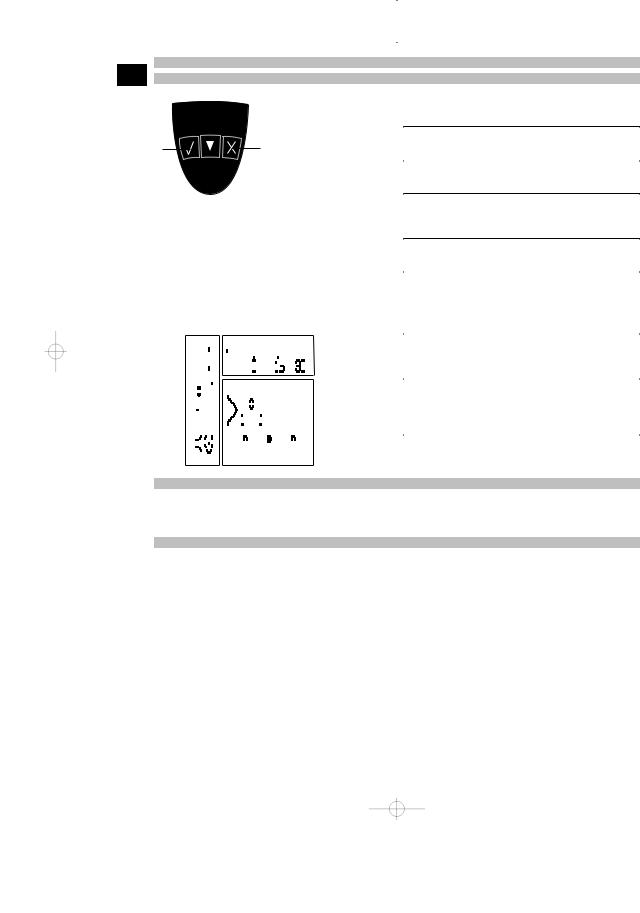
7.2 Operating the scanner en 7.2.1 Control panel and display
Control panel
1
 3
3
2 |
4 |
 5
5
@Arrow butToggle up or down in options or tons values.
; buttonConfirm |
Confirms a value or a selection. |
=On/offton butSwitches the tool on or off.
%Cancel butCancels an input, cancels the ton path being scanned or goes
back one step within a menu.
|
|
|
|
|
|
|
|
|
|
|
|
|
|
|
|
|
|
|
|
|
|
|
|
|
|
|
& |
buttonRecord |
Starts or stops a recording. |
Display |
2 |
|
|
|
|
|
|
|
|
|
|
|
|
|
Menu area. |
Functions that can be selected |
|||||||||||||
|
|
|
|
|
|
|
|
|
|
|
|
|
|
|
|
@ |
|||||||||||||
|
|
|
|
|
|
|
|
|
|
|
|
|
|
|
|
|
|
using the Arrow and Confirm |
|||||||||||
|
|
|
|
|
|
|
|
|
|
|
|
|
|
|
|
|
|
|
|
|
|
|
|
|
|
|
|
|
buttons |
|
|
|
|
|
|
|
|
|
|
|
|
|
|
|
|
|
|
|
|
|
|
|
|
|
|
|
; |
Status in- |
Information such as battery |
|
|
|
|
|
|
|
|
|
|
|
|
|
|
|
|
|
|
|
|
|
|
|
|
|
|
|
|||
|
|
|
|
|
|
|
|
|
|
|
|
|
|
|
|
|
|
|
|
|
|
|
|
|
|
|
|||
|
|
|
|
|
|
|
|
|
|
|
|
|
|
|
|
|
|
|
|
|
|
|
|
|
|
|
|
formation |
charge status and memory |
|
|
|
|
|
|
|
|
|
|
|
|
|
|
|
|
|
|
|
|
|
|
|
|
|
|
|
|
||
1 |
|
|
|
|
|
|
|
|
|
|
|
|
|
|
|
|
|
|
|
|
|
|
|
|
|
3 |
|
|
status. |
|
|
|
|
|
|
|
|
|
|
|
|
|
|
|
|
|
|
|
|
|
|
|
|
|
|
|
|||
|
|
|
|
|
|
|
|
|
|
|
|
|
|
|
|
|
|
|
|
|
|
|
|
|
= |
Variable |
This is where feedback / infor- |
||
|
|
|
|
|
|
|
|
|
|
|
|
|
|
|
|
|
|
|
|
|
|
|
|
|
|||||
|
|
|
|
|
|
|
|
|
|
|
|
|
|
|
|
|
|
|
|
|
|
|
|
|
|
area. |
mation for the user is displayed, |
||
|
|
|
|
|
|
|
|
|
|
|
|
|
|
|
|
|
|
|
|
||||||||||
|
|
|
|
|
|
|
|
|
|
|
|
|
|
|
|
|
|
|
|
|
|
|
|
|
|
|
|
|
e.g. scanning mode, bar depth, |
|
|
|
|
|
|
|
|
|
|
|
|
|
|
|
|
|
|
|
|
|
|
|
|
|
|
|
|
|
scanning progress, etc. |
|
|
|
|
|
|
|
|
|
|
|
|
|
|
|
|
|
|
|
|
|
|
|
|
|
|
|
|
|
|
|
|
|
|
|
|
|
|
|
|
|
|
|
|
|
|
|
|
|
|
|
|
|
|
|
|
|
|
|
|
|
|
|
|
|
|
|
|
|
|
|
|
|
|
|
|
|
|
|
|
|
|
|
|
|
|
|
|
|
|
|
|
|
|
|
|
|
|
|
|
|
|
|
|
|
|
|
|
|
|
|
|
|
|
|
|
|
|
|
|
7.2.2 Switching on and off
Press the on / off button to switch the scanner on or off.
The scanner can be switched off only when the main menu is displayed. To reach this screen, press the Cancel button repeatedly until the main menu is displayed.
7.2.3 Main menu
The system always starts in the main menu. All scanning functions and set-up options are selected here. The battery charge status is displayed at the top of the screen together with the memory status. The various scan modes and settings menus are displayed as symbols on the left side of the screen. Use the Arrow buttons to toggle between these options. Press the Confirm button to confirm the selected option.
12
 Loading...