


 Loading...
DD 250
DD 200/HD 30 DD 200/ST 200
English |
en |
Français |
fr |
ﻲﺑﺮﻋ |
ar |
|
ja |
|
ko |
|
cn |
|
zh |
Printed: 04.09.2017 | Doc-Nr: PUB / 5245926 / 000 / 03

1
Printed: 04.09.2017 | Doc-Nr: PUB / 5245926 / 000 / 031
2
Printed: 04.09.2017 | Doc-Nr: PUB / 5245926 / 000 / 031
3
4
5
6
Printed: 04.09.2017 | Doc-Nr: PUB / 5245926 / 000 / 031
7
8
9
10
Printed: 04.09.2017 | Doc-Nr: PUB / 5245926 / 000 / 031
11
12
13
Printed: 04.09.2017 | Doc-Nr: PUB / 5245926 / 000 / 031
|
DD 250 |
|
|
DD 200/HD 30 |
|
|
DD 200/ST 200 |
|
en |
Original operating instructions . . . . . . . . . . . . . . . . . . . . . . . . . . . . . . . . . . . . . . . |
1 |
fr |
Mode d'emploi original . . . . . . . . . . . . . . . . . . . . . . . . . . . . . . . . . . . . . . . . . . . |
32 |
ar |
ﻲﻠﺻﻷﺍ ﻝﺎﻤﻌﺘﺳﻻﺍ ﻞﻴﻟﺩ . . . . . . . . . . . . . . . . . . . . . . . . . . . . . . . . . . . . . . . . . . |
64 |
ja |
. . . . . . . . . . . . . . . . . . . . . . . . . . . . . . . . . . . . . . . . . . . . |
95 |
ko |
. . . . . . . . . . . . . . . . . . . . . . . . . . . . . . . . . . . . . . . . . . . . . |
124 |
cn |
. . . . . . . . . . . . . . . . . . . . . . . . . . . . . . . . . . . . . . . . . . . . . . . . . . |
153 |
zh |
. . . . . . . . . . . . . . . . . . . . . . . . . . . . . . . . . . . . . . . . . . . . . . . . . . |
178 |
Printed: 04.09.2017 | Doc-Nr: PUB / 5245926 / 000 / 031
Printed: 04.09.2017 | Doc-Nr: PUB / 5245926 / 000 / 031

1 Information about the documentation
1.1 Conventions
1.1.1 Prohibition signs
The following prohibition signs are used:

 Transport by crane is not permissible
1.1.2 Warning signs
The following warning signs are used:
General warning
Warning: hot surface
Warning: hazardous electrical voltage
1.1.3 Mandatory signs
The following mandatory signs are used:
Read the operating instructions before use.
Wear protective gloves
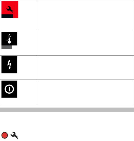
1.1.4 Symbols
The following symbols are used:
Service indicator
Hole-starting mode
Runtime counter
Drilling performance indicator: Increase contact pressure
Drilling performance indicator: Reduce contact pressure
Protective earth
Rated speed under no load
Instructions for use and other useful information
1.1.5 Typographical emphasis
The following typographic features are used to emphasize important passages in this technical documentation:
These numbers refer to the corresponding illustrations.
1
Printed: 04.09.2017 | Doc-Nr: PUB / 5245926 / 000 / 031

1.2 Information notices
On the drill stand, base plate or diamond core drilling machine
On the vacuum base plate
Upper half of the image: An additional means of securing the drill stand must be employed when the machine is used for horizontal drilling with the vacuum securing method.
Lower half of the image: Use of the vacuum securing method without an additional means of securing is prohibited for drilling in an upward direction.
On the diamond core drilling machine
Use of the water collection system in conjunction with a wet-type industrial vacuum cleaner is a mandatory requirement for working overhead.
On the diamond core drilling machine
Operate the system only with a properly functioning PRCD.
1.3Operating instructions
It is essential that the operating instructions are read before initial operation.
Always keep these operating instructions together with the power tool.
Ensure that the operating instructions are with the power tool when it is given to other persons.
Changes and errors excepted.
2
Printed: 04.09.2017 | Doc-Nr: PUB / 5245926 / 000 / 031
1.4Product information
The type designation and serial number can be found on the rating plate on the product. Make a note of this data in the following table and always refer to it when making an inquiry to your Hilti representative or Hilti Service Center.
Product information
|
Diamond core drilling |
DD 250 |
|
|
machine |
DD 200/HD 30 |
|
|
|
DD 200/ST 200 |
|
|
Generation |
02 |
|
|
Serial no. |
|
|
|
|
|
|
2 |
Safety |
|
|
|
|
|
|
2.1 |
Warnings |
|
|
The purpose of warnings
Warnings alert persons to hazards that occur when handling or using the product.
Description of the key words used DANGER
Draws attention to imminent danger that will lead to serious personal injury or fatality.
WARNING
Drawsattentiontoapotentiallydangeroussituationthatcouldleadtoseriouspersonalinjuryorfatality.
CAUTION
Draws attention to a potentially dangerous situation that could lead to slight personal injury or damage to the equipment or other property.
2.2 Safety precautions
The safety precautions given in the following section contain all general safety precautions for power tools which, in accordance with the applicable standards, require to be listed in the operating instructions. Accordingly, some of the rules listed may not be relevant to this power tool.
2.2.1 General safety precautions for power tools
WARNING Ensure that your read all safety precautions, instructions and technical data with which this power tool is provided. Failure to follow the instructions below may result in electric shock, fire and/or serious injury.
Keep all safety precautions and instructions for future reference.
The term “power tool” used in the safety precautions refers to your mains-operated (corded) power tool or battery-operated (cordless) power tool.
Work area safety
Keep your work area clean and well lit. Cluttered or dark work areas invite accidents.
Do not operate the power tool in explosive atmospheres, such as in the presence of flammable liquids, gases or dust. Power tools create sparks which may ignite the dust or fumes.
Keep bystanders, children and visitors away while operating a power tool. Distractions can cause you to lose control of the tool.
Electrical safety
The plug on the supply cord of the power tool must match the power outlet. Do not change the plug in any way. Do not use adapter plugs with earthed (grounded) power tools. Unmodified plugs and matching power outlets reduce the risk of electric shock.
Avoid body contact with earthed or grounded surfaces such as pipes, radiators, cookers, stoves and refrigerators. There is an increased risk of electric shock if your body is grounded.
Do not expose the power tool to rain or wet conditions. Water entering a power tool will increase the risk of electric shock.
Do not abuse the supply cord. Never use the supply cord for carrying, pulling or unplugging the power tool. Keep the supply cord away from heat, oil, sharp edges or moving parts. Damaged or tangled supply cords increase the risk of electric shock.
3
Printed: 04.09.2017 | Doc-Nr: PUB / 5245926 / 000 / 031

When operating a power tool outdoors, use only extension cords of a type suitable for outdoor use. Use of an extension cord suitable for outdoor use reduces the risk of electric shock.
If use of the power tool in a damp environment cannot be avoided, use a ground fault circuit interrupter. Use of a ground fault circuit interrupter reduces the risk of electric shock.
Personal safety
Stay alert, watch what you are doing and use common sense when operating a power tool. Do not use a power tool while you are tired or under the influence of drugs, alcohol or medication. A moment of inattention while operating the power tool may result in serious personal injury.
Wear your personal protective equipment and always wear protective glasses. Depending on the purpose for which the power tool is to be used, wearing safety equipment such as a dust mask, non-skid safety shoes, hard hat, or hearing protection will reduce the risk of injury.
Avoid accidental starting. Check that the power tool is switched off before you connect it to the power supply and/or the battery and before picking it up or carrying it. Carrying power tools with your finger on the switch or plugging in power tools that are already switched on invites accidents.
Remove adjusting keys or switches before turning the power tool on. A tool or a key left attached to a rotating part of the machine may result in personal injury.
Avoid unaccustomed body positions. Maintain proper footing and balance at all times. This will allow you to control the power tool better, even in unexpected situations.
Dress properly. Do not wear loose clothing or jewelry. Keep your hair, clothing and gloves away from moving parts. Loose clothes, jewelry or long hair can be caught in moving parts.
If devices are provided for the connection of dust extraction and collection facilities, ensure these are connected and properly used. The use of a dust removal system can reduce dust-related hazards.
Do not lull yourself into a false sense of security and do not flout the safety rules for power tools, even if you are familiar with the power tool after using it many times. Caress handling could cause serious injury within fractions of a second.
Use of the power tool
Do not overload the tool. Use the correct power tool for your application. The correct power tool will do the job better and more safely within the performance range for which it is designed.
Do not use a power tool if it has a faulty On/Off switch. Any power tool that cannot be controlled with the switch is dangerous and must be repaired.
Disconnect the plug from the power outlet and/or remove a removable battery before making any adjustments, changing accessories, or storing the tool. This precaution reduces the risk of the power tool starting accidentally.
Store idle power tools out of the reach of children . Do not allow persons unfamiliar with the power tool or these instructions to operate the power tool. Power tools are dangerous in the hands of untrained users.
Maintain power tools and accessories carefully. Check that moving parts operate satisfactorily and do not jam, and whether any parts are broken or so damaged that the correct operation of the power tool is adversely affected. If parts are damaged, have the parts repaired before using of the tool. Many accidents are caused by poorly maintained power tools.
Keep cutting tools sharp and clean. Properly maintained tools with sharp cutting edges are less likely to bind and are easier to control.
Use power tools, accessories, insert tools, etc. only as described in this manual. Take the working conditions and the work to be performed into account. Use of the power tool for operations different from those intended could result in a hazardous situation.
Keep grips and gripping surfaces dry, clean and free from oil and grease. Slippery grips and gripping surfaces do not allow the power tool to be safely operated and controlled in unforeseen situations.
Service
Have your power tool repaired only by qualified,skilled personnel, using only genuine Hilti spare parts. The safety of the power tool can thus be maintained.
2.2.2Diamond drill safety warnings
When performing drilling that requires the use of water, route the water away from the operator’s work area or use a liquid collection device. Such precautionary measures keep the operator’s work area dry and reduce the risk of electrical shock.
Operate power tool by insulated grasping surfaces, when performing an operation where the cutting accessory may contact hidden wiring or its own cord. Cutting accessory contacting a “live” wire may make exposed metal parts of the power tool “live” and could give the operator an electric shock.
4
Printed: 04.09.2017 | Doc-Nr: PUB / 5245926 / 000 / 031

Wear hearing protection when diamond drilling. Exposure to noise can cause hearing loss.
When the bit is jammed, stop applying downward pressure and turn off the tool. Investigate and take corrective actions to eliminate the cause of the bit jamming.
When restarting a diamond drill in the workpiece check that the bit rotates freely before starting. If the bit is jammed, it may not start, may overload the tool, or may cause the diamond drill to release from the workpiece.
When securing the drill stand with anchors and fasteners to the workpiece, ensure that the anchoring used is capable of holding and restraining the machine during use. If the workpiece is weak or porous, the anchor may pull out causing the drill stand to release from the workpiece.
When securing the drill stand with a vacuum pad to the workpiece, install the pad on a smooth, clean, non-porous surface. Do not secure to laminated surfaces such as tiles and composite coating. If the workpiece is not smooth, flat or well affixed, the pad may pull away from the workpiece.
Ensure there is sufficient vacuum before and during drilling. If the vacuum is insufficient, the pad may release from the workpiece.
Never perform drilling with the machine secured by the vacuum pad only, except when drilling downwards. If the vacuum is lost, the pad will release from the workpiece.
When drilling through walls or ceilings, ensure to protect persons and the work area on the other side. The bit may extend through the hole or the core may fall out on the other side.
When drilling overhead, always use the liquid collection device specified in the instructions. Do not allow water to flow into the tool. Water entering the power tool will increase the risk of electric shock.
2.2.3Additional safety precautions
Personal safety
Tampering with or modification of the machine is not permitted.
The machine is not intended for use by inexperienced persons who have received no special training.
Keep the machine out of reach of children.
Avoid touching rotating parts. Switch the machine on only after it is in position at the workpiece.
Touching rotating parts, especially rotating accessory tools, may lead to injury.
Avoid skin contact with drilling slurry.
Dust from materials, such as paint containing lead, some kinds of wood, concrete / masonry / stone containing silica, and minerals as well as metal, may be injurious to health. Contact with or inhalation of the dust may cause allergic reactions and/or respiratory or other diseases to the operator or bystanders. Certain kinds of dust are classified as carcinogenic such as oak and beech dust, especially in conjunction with additives for wood conditioning (chromate, wood preservative). Material containing asbestos must only be handled by specialists. Use a dust removal system that is as effective as possible. Accordingly, use a suitable vacuum cleaner of the type recommended by Hilti for wood dust and/or mineral dust and which is designed for use with this power tool. Ensure that the workplace is well ventilated. The use of a dust mask suitable for the particular type of dust is recommended. Observe national regulations applicable to the materials on which you intend to use the machine.
The diamond core drilling machine and the diamond core bit are heavy pieces of equipment. There is a risk of crushing parts of the body. The user and any other persons in the vicinity must wear suitable eye protection, a hard hat, ear protection, protective gloves and safety footwear while the machine is in use.
Careful handling and use of electric tools
Make sure that the machine is correctly fastened in the drill stand.
Take care to ensure that an end stop is always fitted to the drill stand. The safety-relevant end-stop function becomes inoperative if this component is not fitted.
Ensure that the accessory tools used have a mounting system that is compatible with the drilling machine and that they are secured in the chuck correctly.
Electrical safety
Avoid using extension cords with multiple power outlets and the simultaneous use of several machines connected to one extension cord.
Themachinemaybeoperatedonlywhenconnectedtoanadequately-ratedpowersupplyequipped with an earth (ground) conductor.
Before beginning work, check the working area (e.g. using a metal detector) to ensure that no concealed electric cables or gas and water pipes are present. External metal parts of the machine
5
Printed: 04.09.2017 | Doc-Nr: PUB / 5245926 / 000 / 031

may become live, for example, when an electric power line is damaged accidentally. This presents a serious risk of electric shock.
Make sure that the supply cord is not pinched and damaged as the carriage advances.
Never operate the machine without the accompanying PRCD (machines without PRCD: Never operate the machine without an isolating transformer). Test the PRCD each time before use.
Check the machine’s supply cord at regular intervals and have it replaced by a qualified specialist if found to be damaged. If the machine’s supply cord is damaged it must be replaced with a specially-prepared and approved supply cord available from Hilti Customer Service. Check extension cords at regular intervals and replace them if found to be damaged. Do not touch the supply cord or extension cord if it is damaged while working. Disconnect the supply cord plug from the power outlet. Damaged supply cords or extension cords present a risk of electric shock.
Never operate the machine when it is dirty or wet. Dust (especially dust from conductive materials) or dampness adhering to the surface of the machine may, under unfavorable conditions, lead to electric shock. Dirty or dusty machines should thus be checked by Hilti Service at regular intervals, especially if used frequently for working on conductive materials.
Workplace
Approval must be obtained from the site engineer or architect prior to beginning drilling work.
Drilling work on buildings and other structures may influence the static equilibrium of the structure, especially when steel reinforcing bars or load-bearing components are cut through.
If the drill stand has not been fastened correctly, always move the machine mounted on the drill stand all the way down in order to prevent the stand from falling over.
Keep the supply cord, extension cord, water hose and vacuum hose away from rotating parts of the machine.
Use of the water collection system in conjunction with a wet-type industrial vacuum cleaner is a mandatory requirement for wet drilling overhead.
Use of the vacuum securing method without an additional means of fastening is prohibited for drilling in an upward direction.
An additional means of securing the drill stand must be employed when the machine is secured with the vacuum securing method (accessory) for horizontal drilling.
3 Description
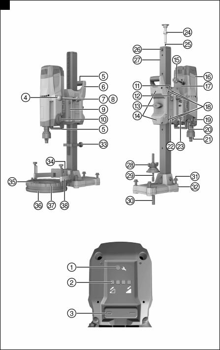
3.1Parts, indicators and operating controls for diamond core drilling machine DD 250/drill stand DDHD 30 1
Diamond core drilling machine DD 250
@Multifunction display
; Button for hole-starting mode = Runtime counter button
% Rating plate
&On/Off switch
( Supply cord cover ) Gear selector
Carriage DD-HD 30
£ Hand wheel shaft 1:1 | Hand wheel shaft 1:3
¡Eccentric pin (lock for the diamond core drilling machine)
Q Shear pin (5x)
Drill stand DD-HD 30
U Threaded spindle (accessory) I Cover
ORail
PCarrying handle
ÜBrace
[ Clamping nut ] Clamping spindle
6
+ Supply cord with PRCD § Water connection
/Carrying handle (2x)
: Carbon brush cover (2x)
∙Water flow regulator
$ Chuck
W Hand wheel
E Leveling indicator (2x) R Carriage lock
T Supply cord guide
Z Carriage play adjusting screw (4x)
Æ Rating plate
ºBase plate
~Anchor
A Hole center indicator
S Leveling screw (3x)
D End stop screw
F Depth gage (accessory)
Printed: 04.09.2017 | Doc-Nr: PUB / 5245926 / 000 / 031

GSealing washer for water collector (accessory)
HWater collector (accessory)
Vacuum base plate (accessory)
Ö Vacuum release valve
ÄVacuum hose connector
†Traversing mechanism adapter
JSeal (accessory)
KWater collector holder (accessory)
LTraversing mechanism adapter
ΠPressure gage
ÅVacuum seal
ªLeveling screw (4x)
3.2Parts, indicators and operating controls for diamond core drilling machine DD 200/drill stand DDST 200 2
Diamond core drilling machine DD 200 |
|
Carriage lock |
||
@ |
Service indicator |
$ |
||
; |
Drilling performance indicator |
£ |
Screw for adjusting the play between |
|
= |
On/Off switch |
|
carriage and roller (2x) |
|
% |
Hand wheel |
| |
Supply cord with PRCD |
|
|
¡ |
Carbon brush cover (2x) |
||
& |
Carrying handles (2x) |
|||
|
Q |
Supply cord cover |
||
( |
Carriage casing |
|||
|
W |
Screw for adjusting the play between |
||
) |
Hand wheel shaft |
|||
|
|
carriage and sliding piece (4x) |
||
+ |
Shear pin (2x) |
|
||
E |
Water flow regulator |
|||
§ |
Intermediate piece |
|||
R |
Water connection |
|||
/ |
Gear selector |
|||
T |
Chuck |
|||
: |
Adjusting screw hexagon socket wrench |
|||
Z |
Rating plate |
|||
∙ |
Supply cord guide |
|||
U |
Intermediate piece screw (4x) |
|||
|
|
|||
DDST 200 drill stand |
|
Base plate |
||
I |
Threaded spindle (accessory) |
~ |
||
O |
Threaded spindle chuck |
A |
Depth gage (accessory) |
|
P |
End stop screw |
S |
Spacer for water collector holder (acces- |
|
Ü |
Rail |
|
sory) |
|
[ |
Clamping nut |
D |
Sealing washer for water collector (acces- |
|
|
|
sory) |
||
] |
Clamping spindle |
|
||
F |
Seal (accessory) |
|||
Æ |
Anchor |
|||
G |
Water collector (accessory) |
|||
º |
Leveling screw (4x) |
|||
H |
Water collector holder (accessory) |
|||
|
|
|||
3.3 Intended use
The product described is an electrically powered diamond core drilling machine. It is designed for drilling through-holes and blind holes in (reinforced) mineral base materials using a drill stand and the wet drilling technique. Hand-held use of the diamond core drilling machine is not permitted.
The product described is designed for professional use and may be operated, serviced and maintained only by trained, authorized personnel. This personnel must be informed of any particular hazards that may be encountered. The product described and its ancillary equipment may present hazards when used incorrectly by untrained personnel or when used not as directed.
Always use a drill stand when using the diamond core drilling machine. The drill stand must be sufficiently anchored in the base material by an anchor or vacuum base plate.
Do not use a hammer or other heavy object when making adjustments to the base plate.
The tool may be operated only when connected to a power supply providing a voltage and frequency in compliance with the information given on its rating plate.
Observe the national health and safety requirements.
Observe the safety rules and operating instructions for the accessories used.
To reduce the risk of injury, use only genuine Hilti core bits and accessories.
3.4DD 250: Display symbols and explanations on the multifunction display of the diamond core drilling machine
For the following indicators, the diamond core drilling machine must be ready for operation (plugged in and with a switched-on PRCD).
7
Printed: 04.09.2017 | Doc-Nr: PUB / 5245926 / 000 / 031

|
The status bar displays various pieces of information regarding the ma- |
|
|
chine’s current status, such as the gear engaged or the activated hole- |
|
|
starting mode. |
|
Status bar for information |
|
|
|
The status bar displays various warning indicators that do not cause the |
|
|
diamond core drilling machine to stop immediately, such as (from right to |
|
|
left) time remaining until the carbon brushes have to be replaced, when |
|
|
service is necessary or if there is a fault in the power supply. |
|
Status bar for warning |
|
|
messages |
|
|
|
The diamond core drilling machine is not switched on. The indicator helps |
|
|
level the system and align the drill stand when drilling at an angle. The |
|
|
indicator displays the alignment of the diamond core drilling machine |
|
|
symbolically and in degrees. |
|
|
Note |
|
Spirit level |
Angular accuracy at room temperature: ±2° |
|
|
The diamond core drilling machine is running under no load. The indicator |
|
|
helps ensure that the gear engaged is suitable for the diamond core bit |
|
|
used. At the top left, the indicator displays the gear engaged and in the |
|
|
center, the recommended core bit diameter range in millimeters and inches |
|
|
for this gear. |
|
Gear indicator for first to |
|
|
fourth gear |
|
|
|
The diamond core drilling machine is switched off or running under no load. |
|
|
The function makes it possible to start holes with low vibration in the case |
|
|
of core bits with a large diameter. This function can be deactivated at any |
|
|
time by pressing the button for the hole-starting mode again |
|
|
Note |
|
Hole-starting mode is |
The indicator is automatically hidden after a few seconds. |
|
active |
|
|
|
The diamond core drilling machine is drilling. The button for activating |
|
|
hole-starting mode was pressed while the diamond core drilling machine |
|
|
was under load, was being run-in after the carbon brushes had been |
|
|
changed, or was in cool-down mode, or immediately after the diamond |
|
|
core drilling machine had been operated for two minutes in hole-starting |
|
The hole-starting mode |
mode. Activation is not possible. |
|
Note |
||
cannot be activated |
||
The indicator is automatically hidden after a few seconds. |
||
|
||
|
The diamond core drilling machine is drilling. The hole-starting mode is |
|
|
active. The indicator displays the time remaining until the diamond core |
|
|
drilling machine automatically switches off. |
|
|
Note |
|
|
To protect the diamond core drilling machine, the hole-starting mode |
|
Running time for the hole- |
automatically switches off after a maximum of two minutes. |
|
starting mode |
|
8
Printed: 04.09.2017 | Doc-Nr: PUB / 5245926 / 000 / 031

|
The diamond core drilling machine is drilling. The hole-starting mode is not |
|
|
active. The indicator helps ensure that the diamond core drilling machine is |
|
|
being operated in the optimal range. Background color: Yellow. |
|
|
The contact pressure is too low. Increase the contact pressure. |
|
Drilling performance |
|
|
indicator: Contact pressure |
|
|
is too low |
|
|
|
The diamond core drilling machine is drilling. The hole-starting mode is not |
|
|
active. The indicator helps ensure that the diamond core drilling machine is |
|
|
being operated in the optimal range. Background color: Green. |
|
|
The contact pressure is at the optimum level. |
|
Drilling performance |
|
|
indicator: Optimum contact |
|
|
pressure |
|
|
|
The diamond core drilling machine is drilling. The hole-starting mode is |
|
|
not active. It is indicated that rated current has exceeded the limit of 20 A. |
|
|
Background color: Green. |
|
|
The contact pressure is too high. Reduce the contact pressure. |
|
Rated current limit has |
|
|
been exceeded |
|
|
|
The diamond core drilling machine is drilling. The hole-starting mode is not |
|
|
active. The indicator helps ensure that the diamond core drilling machine is |
|
|
being operated in the optimal range. Background color: Red. |
|
|
The contact pressure is too high. Reduce the contact pressure. |
|
Drilling performance |
|
|
indicator: Contact pressure |
|
|
is too high |
|
|
|
The button for the runtime counter has been pressed. At the top, the indi- |
|
|
cator displays the drilling time (the diamond core drilling machine is drilling) |
|
|
and, at the bottom, the diamond core drilling machine's operating hours |
|
|
(diamond core drilling machine is switched on) in hours, minutes and sec- |
|
|
onds. Press the button for the runtime counter for a few seconds to reset |
|
Runtime counter |
the drilling time total to zero. |
|
Note |
||
|
||
|
The indicator is automatically hidden after a few seconds or by pressing the |
|
|
button again. |
|
|
The diamond core drilling machine is running. The carbon brush wear |
|
|
limit has almost been reached. The indicator helps ensure that the carbon |
|
|
brushes are replaced in good time. The time remaining until the diamond |
|
|
core drilling machine automatically switches off is displayed in hours and |
|
|
minutes. The indicator is automatically hidden after a few seconds. |
|
Time remaining until the |
|
|
carbon brushes are to be |
|
|
replaced |
|
|
|
The carbon brushes are worn. The carbon brushes must be replaced. |
|
|
An internal fault has occurred. |
|
Service indicator |
|
|
|
9 |
Printed: 04.09.2017 | Doc-Nr: PUB / 5245926 / 000 / 031
The diamond core drilling machine is running. The carbon brushes have been changed and must be run in by letting the machine run under no load for at least one minute without interruption, in order to achieve the optimum service life. The indicator displays the time remaining until the running-in process is completed.
Running in after the carbon brushes have been replaced
The diamond core drilling machine has overheated. It is no longer running or is in cool-down mode. The indicator displays the time remaining until the diamond core drilling machine cools down. If the diamond core drilling machine is still too hot after this time has elapsed, the remaining running time starts from the beginning again.
Overheating
Undervoltage occurred in the supply network. In the event of undervoltage, the diamond core drilling machine cannot be operated at full power.
Note
The indicator is automatically hidden after a few seconds.
Fault in the power supply
Maximum running time with hole-starting mode active has been exceeded; Fault in the power supply; The diamond core drilling machine has been overloaded; Overheated, water has entered the motor or the cooling running time has ended.
Restart interlock
3.5 DD 200: Service indicator and drilling performance indicator
The diamond core drilling machine is equipped with a service indicator and an LED drilling performance indicator. For the following indicators, the diamond core drilling machine must be ready for operation (plugged in and with a switched-on PRCD).
Status |
Meaning |
|
|
Lights up red |
• The diamond core drilling machine is |
|
|
in working order. The carbon brush |
|
|
wear limit has almost been reached. |
|
|
The indicator helps ensure that the |
|
|
carbon brushes are replaced in good |
|
|
time. After the lamp lights up for the |
|
|
first time, the machine may continue |
|
|
to be used for several hours before |
|
|
the automatic cut-out is activated. |
|
|
• The diamond core drilling machine |
|
|
is in working order. The carbon |
|
|
brushes have been changed and |
|
|
must be run in by letting the machine |
|
|
run under no load for at least one |
|
|
minute without interruption, in order |
|
|
to achieve the optimum service life. |
|
|
• The diamond core drilling machine |
|
|
is no longer in working order. The |
|
|
carbon brushes are worn. The |
|
|
carbon brushes must be replaced. |
|
|
• The diamond core drilling machine is |
|
|
no longer in working order. Damage |
|
|
to the diamond core drilling machine. |
10 |
|
|
Printed: 04.09.2017 | Doc-Nr: PUB / 5245926 / 000 / 031
Status |
Meaning |
||
|
Flashing red light |
• |
Overheating. See “Troubleshooting”. |
|
|
|
|
|
The LED on the left lights yellow. |
• Contact pressure is too low. |
|
|
|
|
|
|
The LEDs in the middle light green. |
• The contact pressure is at the |
|
|
|
|
optimum level. |
|
|
|
|
|
The LED on the right lights red. |
• Contact pressure is too high. |
|
|
|
|
|
|
LED on the right-hand side flashes red |
• |
Contact pressure is too high. |
|
|
|
The rated current limit has been |
|
|
|
exceeded. |
|
|
|
|
3.6 Items supplied |
|
|
|
Note
To help ensure safe and reliable operation, use only genuine Hilti spare parts and consumables. Spare parts, consumables and accessories approved by Hilti for use with the product can be found at your local Hilti Center or online at: www.hilti.com
Items supplied: DD 250/DD 200 for DDHD 30
Diamond core drilling machine, operating instructions.
Items supplied: DD 200 for DDST 200
Diamond core drilling machine, hand wheel/lever, hexagon socket wrench, operating instructions.
3.7 Accessories and spare parts QR codes
Note
Scan the applicable QR code with your smartphone for further information.
DD 200 for drill standDD-HD 30
DD 200 for drill standDD-ST 200
11
Printed: 04.09.2017 | Doc-Nr: PUB / 5245926 / 000 / 031

DD 250 for drill standDD-HD 30
Spare parts |
|
Item number |
Designation |
51279 |
Hose connector |
2006843 |
Carbon brushes 220-240 V |
2104230 |
Carbon brushes 100-127 V |
|
|
4 Technical data |
|
|
|
4.1 Diamond core drilling machine |
|
When powered by a generator or transformer, the generator or transformer’s power output must be at least twice the rated input power shown on the rating plate of the power tool. The operating voltage of the transformer or generator must always be within +5% and -15% of the rated voltage of the power tool.
The information given applies to a rated voltage of 230 V. The data may vary in the event of deviations from the rated voltage and for country-specific versions. Please refer to the power tool’s rating plate for details of its voltage, frequency, current and input power ratings.
Information for users as per EN 61000-3-11: Switching on causes a brief drop in voltage. Other appliances may be negatively affected on mains supplies where conditions are unfavorable. No malfunctions are to be expected in mains supplies with an impedance of less than 0.4287 ohms.
|
|
DD 250 |
DD 200 for |
DD 200 for |
|
|
|
DDHD 30 |
DDST 200 |
Weight in accordance with EPTA |
15.3 kg |
14.6 kg |
20.4 kg |
|
procedure 01/2003 |
|
|
|
|
Weight of the drill |
DD-HD 30 |
21.4 kg |
21.4 kg |
•/• |
stand in accor- |
|
|
|
|
dance with EPTA |
DDST 200 |
•/• |
•/• |
12.3 kg |
procedure 01/2003 |
||||
Drilling depth without |
extension |
500 mm |
500 mm |
500 mm |
Permissible water supply pressure |
≤ 6 bar |
≤ 6 bar |
≤ 6 bar |
|
Rated speed under |
1st gear |
240 rpm |
240 rpm |
240 rpm |
no load |
2nd gear |
580 rpm |
580 rpm |
580 rpm |
|
3rd gear |
1,160 rpm |
1,160 rpm |
1,160 rpm |
|
4th gear |
2,220 rpm |
•/• |
•/• |
Optimum core bit |
1st gear |
152 mm … 450 mm |
152 mm … 500 mm |
152 mm … 500 mm |
diameter |
2nd gear |
82 mm … 152 mm |
82 mm … 152 mm |
82 mm … 152 mm |
|
3rd gear |
35 mm … 82 mm |
35 mm … 82 mm |
35 mm … 82 mm |
|
4th gear |
12 mm … 35 mm |
•/• |
•/• |
Ideal distance between the marking |
330 mm |
330 mm |
380 mm |
|
on the anchor base plate and the |
|
|
|
|
hole center |
|
|
|
|
Ideal distance between the marking |
165 mm |
165 mm |
215 mm |
|
on the vacuum base plate and the |
|
|
|
|
hole center |
|
|
|
|
12 |
|
|
|
|
Printed: 04.09.2017 | Doc-Nr: PUB / 5245926 / 000 / 031
4.2 Permissible core bit diameters for various items of equipment
Note
The approved drilling directions for the various items of equipment must be observed.
Use of a wet/dry vacuum cleaner with a water collection system is mandatory for drilling upwards.
|
DD 250 |
DD 200 for DDHD 30 |
DD 200 for DDST 200 |
Ø without accessories |
12 mm … 300 mm |
35 mm … 300 mm |
35 mm … 400 mm |
Ø with spacer |
12 mm … 450 mm |
35 mm … 500 mm |
35 mm … 500 mm |
Ø with water collec- |
12 mm … 250 mm |
35 mm … 250 mm |
35 mm … 250 mm |
tion system and wet- |
|
|
|
type industrial vacuum |
|
|
|
cleaner |
|
|
|
4.3 Noise information and vibration values determined in accordance with EN 62841
The sound pressure and vibration values given in these instructions have been measured in accordance with a standardized test and may be used to compare one power tool with another. They may be used for a preliminary assessment of exposure. The data given represents the main applications of the power tool. However, if the power tool is used for different applications, with different accessory tools, or is poorly maintained, the data may vary. This may significantly increase exposure over the total working period. An accurate estimation of exposure should also take into account the times when the power tool is switched off, or when it is running but not actually being used for a job. This may significantly reduce exposure over the total working period. Identify additional safety measures to protect the operator from the effects of noise and/or vibration, for example: maintain the tool and the accessories, keep the hands warm, organization of work patterns.
Noise emission values determined in accordance with EN 62841
Sound (power) level (LWA) |
109 dB(A) |
Uncertainty for the sound power level (KWA) |
3 dB(A) |
Sound pressure level (LpA) |
93 dB(A) |
Uncertainty for the sound pressure level (KpA) |
3 dB(A) |
Total vibration (vector sum of three directions), measured in accordance with EN 62841
Triaxial total vibration (vector sum of vibration) at the hand wheel (star handle) does not exceed 2.5 m/s² (including uncertainty K) in accordance with EN 62841-3-6.
5 Operation
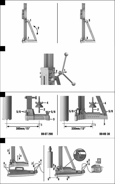
5.1 DD-HD 30: Setting up the drill stand and setting the drilling angle 3
CAUTION
Risk of injury Risk of crushing parts of the body. Releasing the tilt mechanism on the drill stand may cause the rail to tilt suddenly.
Exercise caution. Wear protective gloves.
CAUTION
Risk of injury Hazard presented by a falling diamond core drilling machine.
Always fit the cover at the end of the rail. The cover provides protection and acts as an end stop.
1.Loosen the screw at the pivoting joint at the bottom end of the rail and the screw at the top end of the brace.
2.Adjust the rail to the desired angle.
Note
The angle scale at the rear serves as an adjustment aid.
3. Retighten the two screws securely.
13
Printed: 04.09.2017 | Doc-Nr: PUB / 5245926 / 000 / 031

5.2DD-HD 30: Locking the carriage on the drill stand
1.Pivot the carriage lock in the locked position.The locking pin must engage in this position.
2.Slightly turn the hand wheel to ensure that the carriage is securely locked.
5.3Fitting the hand wheel on the drill stand 4
Note
The hand wheel may be fitted on the left-hand or on the right-hand side of the carriage.
In the case of the DDHD 30 drill stand, the hand wheel may be fitted on the carriage on two different axes. The upper axis directly affects the carriage drive and the lower axis affects the carriage drive with a gear reduction of 1:3.
1.Pull the black ring back to fit the hand wheel.
2.Fit the hand wheel onto the axle.
5.4Fastening the drill stand with an anchor 5
WARNING
Risk of injury The tool may become detached and cause damage if the wrong anchor is used.
Use an anchor suitable for the base material on which you are working and observe the anchor manufacturer’s instructions. Please contact Hilti Technical Service if you have any questions about secure fastening.
Note
Hilti metal expansion anchors M16 (5/8") are usually suitable for fastening diamond core drilling equipment to uncracked concrete. Under certain conditions, however, it may be necessary to use an alternative fastening method. Please contact Hilti Technical Service if you have any questions about secure fastening.
1.Fit the anchor that is suitable for the corresponding base material. Select the distance according to the base plate used.
Note
Ideal distance from the hole center for DD-HD 30: 330 mm (13 in)
Ideal distance from the hole center for DD-ST 200: 380 mm (15 in)
2.Screw the clamping spindle (accessory) into the anchor.
3.Place the drill stand over the spindle and align it. When using the DD-HD 30 drill stand, use the hole center indicator to help you align the drill stand. When a spacer is used, the drill stand cannot be aligned using the hole center indicator.
4.Screw the clamping nut onto the spindle but do not tighten it.
5.Level the base plate by turning the leveling screws. Use the leveling indicators for this purpose. Take care to ensure that the leveling screws make firm contact with the underlying surface.
6.Tighten the leveling screws evenly until the drill stand is securely fastened.
7.Make sure that the drill stand is fastened securely.
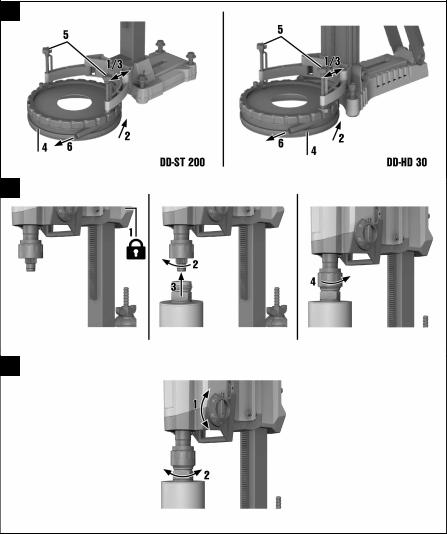
5.5Fastening the drill stand with the vacuum base plate (accessory) 6
DANGER
Risk of injury Hazard presented by a falling diamond core drilling machine.
Fastening the drill stand to the ceiling only by means of the vacuum securing method is not permissible. A heavy structural support or a threaded spindle, for example, can serve as an additional means of fastening.
14
Printed: 04.09.2017 | Doc-Nr: PUB / 5245926 / 000 / 031

WARNING
Risk of injury Hazard presented by a falling diamond core drilling machine.
When drilling horizontally, the drill stand must be secured additionally by a chain.
WARNING
Risk of injury Pressure check
Before beginning drilling and during operation, it must be ensured that the pressure gage indicator remains within the green area.
Note
Make sure that the anchor base plate lies flat against the vacuum base plate and that the two plates are securely connected when using the drill stand with an anchor base plate. Screw the anchor base plate securely onto the vacuum base plate. Make sure that the core bit selected for use will not damage the vacuum base plate.
Before positioning the drill stand, ensure that there is sufficient space available for assembly and operation.
Use the vacuum fastening method only together with core bits of up to 300 mm (12") in diameter and when no spacer is fitted.
A vacuum release valve, which can be used to increase the vacuum again, is fitted to the hand grip on the vacuum base plate.
1.Turn all leveling screws back until they project approximately 5 mm (1/5 in) beneath the vacuum base plate.
2.Connect the vacuum connector on the vacuum base plate to the vacuum pump.
3.Place the drill stand on the vacuum base plate.
4.Fit the drill stand using the screw supplied with a washer underneath on the vacuum base plate and tighten the screw.
Note
DD-HD 30: Use the thinner of the two washers supplied.
DD-ST 200: Use the thicker of the two washers supplied.
5.Locate the center point of the hole to be drilled. Draw a line from the center of the hole to be drilled towards where the drill stand is to be positioned.
6.Make a mark on the line at the distance stated from the center of the hole to be drilled. Bring the middle of the front edge of the vacuum base plate into alignment with the mark made.
Note
Take care to ensure that the base material on which the vacuum base plate is positioned is flat and clean.
Ideal distance from the hole center for DD-HD 30: 165 mm (6 1/2 in) Ideal distance from the hole center for DD-ST 200: 215 mm (8 1/2 in)
7.Switch on the vacuum pump, press the vacuum release valve and keep it pressed.
8.Once the drill stand has been positioned correctly, release the vacuum release valve and press the vacuum base plate against the base material.
9.Level the vacuum base plate by turning the leveling screws. Use the leveling indicators for this purpose.
Note
The anchor base plate cannot and should not be leveled on the vacuum base plate.
10.Make sure that the drill stand is fastened securely.
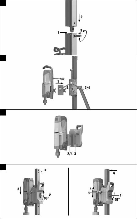
5.6DD-HD 30: Fastening the drill stand with the threaded spindle (accessory)
1.Remove the cover (with built-in end stop) from the top end of the rail.
2.Fit the cylindrical connector on the threaded spindle into the end of the rail on the drill stand.
3.Secure the threaded spindle by turning the eccentric pin.
4.Position the drill stand on the work surface.
15
Printed: 04.09.2017 | Doc-Nr: PUB / 5245926 / 000 / 031

5.Level the base plate by turning the leveling screws.
6.Secure the drill stand with the threaded spindle and tighten the threaded spindle.
7.Make sure that the drill stand is fastened securely.
5.7DDST 200: Fastening the drill stand with the threaded spindle (accessory)
1.Fasten the threaded spindle at the upper end of the rail.
2.Position the drill stand on the work surface.
3.Level the base plate by turning the leveling screws.
4.Secure the drill stand with the threaded spindle and tighten the threaded spindle.
5.Make sure that the drill stand is fastened securely.
5.8DD-HD 30: Extending the rail (accessory) on the drill stand 7
Note
When starting holes, use only core bits or extended core bits with a maximum total length of 650 mm (25 1/2 in).
A depth gage on the rail can be used as an additional end stop.
After removing the extension rail, the cover (with integrated end stop) must be refitted to the drill stand in order to ensure that the safety-relevant end-stop function is restored. The safety-relevant end-stop function becomes inoperative if this component is not fitted.
1.Remove the cover (with built-in end stop) from the top end of the rail. Fit the cover on the extension rail.
2.Fit the cylindrical connector on the extension rail into the end of the rail on the drill stand.
3.Secure the extension rail by turning the eccentric pin.
5.9DD-HD 30: Fitting the spacer (accessory) 8
WARNING
Risk of injury. The fastening may become overloaded.
When one or more spacers are used, the contact pressure must be reduced in order to avoid overloading the fastening.
Note
The diamond core drilling machine should not already be mounted on the drill stand when the spacer is being fitted.
Note
When core bits with a diameter of 300 mm (11 1/2 in) or greater are used, the distance between the drill stand and the drilling axis must be increased by fitting one or two spacers. The hole center indicator is no longer functional when spacers are used.
1.Lock the carriage on the rail with the carriage lock.
2.Pull out the eccentric pin for locking the diamond core drilling machine on the carriage.
3.Place the spacer into the carriage.
4.Push the eccentric pin into the carriage as far as it will go.
5.Tighten the eccentric pin.
6.Check to ensure that the spacer is securely fastened.
5.10DDST 200: Fitting the spacer (accessory) 9
WARNING
Risk of injury. The fastening may become overloaded.
When one or more spacers are used, the contact pressure must be reduced in order to avoid overloading the fastening.
16
Printed: 04.09.2017 | Doc-Nr: PUB / 5245926 / 000 / 031

Note
When core bits with a diameter of 400 mm (15 3/4 in) or greater are used, the distance between the drill stand and the drilling axis must be increased by fitting a spacer.
1.Detach the diamond core drilling machine from the drill stand.
2.Separate the carriage from the diamond core drilling machine by loosening the four screws on the carriage.
3.Screw the spacer tightly to the carriage with the four screws that are additionally supplied.
4.Re-screw the diamond core drilling machine tightly to the spacer with the four screws.
5.11DD-HD 30: Attaching the diamond core drilling machine to the drill stand 8
CAUTION
Risk of injury Hazard presented by inadvertent starting of the diamond core drilling machine.
The diamond core drilling machine should not be connected to the power supply during set-up.
1.Lock the carriage on the rail with the carriage lock.
2.Pull out the eccentric pin for locking the diamond core drilling machine on the carriage.
3.Fit the diamond core drilling machine onto the carriage or the spacer.
4.Push the eccentric pin into the carriage or the spacer as far as it will go.
5.Tighten the eccentric pin.
6.Fasten the supply cord in the cord guide to the carriage cover.
7.Check to ensure that the diamond core drilling machine is securely fastened to the drill stand.
5.12DDST 200: Attaching the diamond core drilling machine to the drill stand 10
DANGER
Risk of injury Impact as a result of a fast-moving lever or hand wheel when the carriage is in motion.
The lever and the hand wheel must not be fitted on the drill stand when the diamond core drilling machine is being fitted.
CAUTION
Risk of injury Hazard presented by inadvertent starting of the diamond core drilling machine.
The diamond core drilling machine should not be connected to the power supply during set-up.
Note
The drive unit and the carriage form a unit. The diamond core drilling machine can thus be removed from the drill stand together with the carriage.
Adjust the play between the rail and carriage before using the tool for the first time.
1.Remove the end stop screw from the end of the rail.
2.Ensure that the carriage lock is open.
3.Mount the diamond core drilling machine on the drill stand by sliding the opening in the carriage over the end of the rail.
4.Lock the carriage on the rail by turning the carriage lock through 90°.
5.Slightly turn the hand wheel to ensure that the diamond core drilling machine is securely fastened.
6.Refit the end stop screw to the end of the rail. The safety-relevant end-stop function becomes inoperative if this component is not fitted.
17
Printed: 04.09.2017 | Doc-Nr: PUB / 5245926 / 000 / 031

5.13Fitting the water connection (accessory)
CAUTION
RiskofpersonalinjuryandmaterialdamageThehosemaybecomedamagedifitisusedincorrectly.
Regularly check the hoses for damage and make sure that the maximum permissible water supply pressure of 6 bar is not exceeded.
Make sure that the hose does not come into contact with rotating parts.
Make sure that the hose is not damaged as the carriage advances.
Maximum water temperature: 40 °C.
Check the water supply system to ensure there are no leaks.
Note
To avoid damage to the components, use only fresh water containing no dirt particles. A flow meter (accessory) may be fitted between the tool and the water supply hose.
1.Connect the water flow regulator to the diamond core drilling machine.
2.Connect the water supply (hose connection).
5.14Fitting the water collection system (accessory) 11
WARNING
Risk of personal injury and material damage The diamond core drilling machine may become damaged and the risk of electric shock is increased.
Water must not be allowed to run over the motor and cover.
Use of a wet-type industrial vacuum cleaner is a mandatory requirement for drilling in an upwards direction.
Note
The diamond core drilling machine must be at a 90° angle to the ceiling. The water collection system sealing disc must match the diamond core bit diameter.
Note
Use of the water collection system allows water to be led away under control, thus preventing the surrounding area from being heavily soiled. The best results are achieved with a wet-type industrial vacuum cleaner.
Note
When using the drill stand DDST 200: Before fitting the water collector holder, screw the spacer for the water collector holder tightly to the drill stand.
1.Loosen the screw on the front of the drill stand at the bottom end of the rail.
2.Slide the water collector holder into position under the screw from below.
3.Tighten the screw securely.
4.Position the water collector, with seal and water collector sealing disc fitted, between the two movable arms of the holder.
5.Secure the water collector to the holder with the two screws.
6.Connect a wet-type industrial vacuum cleaner to the water collector or establish a hose connection through which the water can drain away.
5.15Setting the depth gage (accessory)
1.Turn the hand wheel until the core bit is in contact with the base material.
2.Set the desired drilling depth by adjusting the distance of the depth gage from the carriage.
3.Lock the depth gage in position.
18
Printed: 04.09.2017 | Doc-Nr: PUB / 5245926 / 000 / 031

5.16Fitting the diamond core bit (BL chuck) 12
DANGER
Risk of injury Fragments of the workpiece or of broken insert tools may be ejected and cause injury beyond the immediate area of operation.
Do not use damaged insert tools. Check the insert tools for chipping, cracks, or heavy wear each time before use.
CAUTION
Risk of injury The tool becomes hot as a result of use. It may have sharp edges.
Wear protective gloves when changing the tool.
Note
Diamond core bits must be replaced when the cutting performance and/or rate of drilling progress drops significantly. This generally is the case when the diamond segments reach a height of less than 2 mm (1/16 in).
1.Lock the carriage on the rail with the carriage lock. Check to ensure that it is securely fastened.
2.Open the chuck by turning it in the direction of the "Open brackets" symbol.
3.From below, push the connection end of the diamond core bit into the chuck on the diamond core drilling machine, making sure that the teeth engage.
4.Close the chuck by turning it in the direction of the "Closed brackets" symbol.
5.Check that the diamond core bit is seated securely in the chuck.
5.17Fitting the diamond core bit with an alternative type of chuck
1.Lock the drive spindle with a suitable open-end wrench.
2.Tighten the core bit with a suitable open-end wrench.
5.18Selecting the speed 13
Note
Press the switch only when the tool is stationary.
1.Select the switch setting according to the core bit diameter used.
2.When turning the switch, rotate the core bit by hand at the same time until the switch can be set in the recommended position.
5.19PRCD ground fault circuit interrupter
1.Plug the diamond core drilling machine’s mains plug into an earthed/grounded power outlet.
2.Press the "I" or "RESET" button on the PRCD ground fault circuit interrupter.
The indicator lights up.
3.Press the "0" or "TEST" button on the PRCD ground fault circuit interrupter.
The indicator goes out.
WARNING
Risk of injury Risk of electric shock.
If the indicator continues to light up, further operation of the diamond core drilling machine is not permissible. Have your diamond core drilling machine repaired by Hilti Service.
4.Press the "I" or "RESET" button on the PRCD ground fault circuit interrupter.
The indicator lights up.
19
Printed: 04.09.2017 | Doc-Nr: PUB / 5245926 / 000 / 031

5.20Operating the diamond core drilling machine
WARNING
Risk of personal injury and material damage The diamond core drilling machine may become damaged and the risk of electric shock is increased.
Use of the water collection system in conjunction with a wet-type industrial vacuum cleaner is a mandatory requirement for wet drilling overhead.
DANGER
Risk of personal injury and material damage The wet-type industrial vacuum cleaner switches on and off with a delay. This allows water to run over the diamond core drilling machine. The diamond core drilling machine may become damaged and the risk of electric shock is increased.
When drilling in an upward direction, the wet-type industrial vacuum cleaner must be switched on manually before opening the water supply valve and switched off again manually after closing the water supply valve.
DANGER
Risk of personal injury and material damage The diamond core drilling machine may become damaged and the risk of electric shock is increased.
When drilling in an upward direction, stop working if the suction removal system stops working (e.g. the wet-type industrial vacuum cleaner is full).
WARNING
Risk of personal injury and material damage The water collector cannot function correctly during drilling in an upward direction at an angle. The diamond core drilling machine may become damaged and the risk of electric shock is increased.
Do not drill in an upward direction at an angle.
Note
DD 250: Pressing the button for the hole-starting mode (when the machine is idling or operating under no load) reduces the speed for starting holes. This makes it possible for diamond core bits of large diameters to start holes with greater ease and less vibration. Pressing the button for the hole-starting mode again deactivates this function and the diamond core drilling machine adjusts up to the preset speed. If the function for starting holes is not deactivated before a maximum of two minutes has expired, the diamond core drilling machine automatically switches off.
1.Slowly open the water flow regulator until the desired volume of water is flowing.
2.Press the On/Off switch on the diamond core drilling machine to "I".
3.Release the carriage locking mechanism.
4.Turn the hand wheel until the core bit is in contact with the base material.
5.When beginning drilling, apply only light pressure, until the core bit has centered itself. Only increase the pressure afterwards.
6.Regulate the contact pressure while observing the drilling performance indicator.
5.21Switching off the diamond core drilling machine
WARNING
Risk of personal injury and material damage The diamond core bit fills with water during overhead drilling. The diamond core drilling machine may become damaged and the risk of electric shock is increased.
As a first step, carefully allow the water to drain away after completing overhead drilling. This is done by disconnecting the water supply from the water flow regulator and draining the water by opening the water flow regulator. Do not allow the water to run over the motor and cover.
1. Connect the water flow regulator to the diamond core drilling machine.
20
Printed: 04.09.2017 | Doc-Nr: PUB / 5245926 / 000 / 031

2.Remove the diamond core bit from the hole.
3.Switch off the diamond core drilling machine.
4.Lock the carriage on the rail with the carriage lock.
5.Switch off the wet-type industrial vacuum cleaner (if used).
5.22DD-HD 30: Detaching the diamond core drilling machine from the drill stand
1.Lock the carriage on the rail with the carriage lock.
2.Remove the supply cord from the cord guide on the carriage cover.
CAUTION
Risk of personal injury and material damage Hazard presented by a falling diamond core drilling machine.
Hold the core drilling machine tightly with one hand by the carrying handle.
3.Loosen the eccentric pin for locking the tool on the carriage.
4.Pull out the eccentric pin.
5.Remove the diamond core drilling machine from carriage.
6.Push the eccentric pin into the carriage as far as it will go.
5.23DDST 200: Detaching the diamond core drilling machine from the drill stand
Note
The drive unit and the carriage form a unit. The diamond core drilling machine can thus be removed from the drill stand together with the carriage.
1.Remove the end stop screw from the end of the rail.
2.Release the carriage locking mechanism.
3.Detach the diamond core drilling machine from the drill stand.
4.Refit the end stop screw to the end of the rail. The safety-relevant end-stop function becomes inoperative if this component is not fitted.
6 Care, maintenance, transport and storage
6.1Care of the product
Keep the product, especially its grip surfaces, clean and free from oil and grease. Do not use cleaning agents containing silicone.
Never operate the product when the air vents are blocked. Clean the air vents carefully using a dry brush. Do not allow foreign objects to enter the interior of the product.
Clean the outside of the tool at regular intervals with a slightly damp cloth. Do not use a spray, steam pressure cleaning equipment or running water for cleaning.
Always keep the connection end of the core bit clean and lightly greased.
After carrying out care and maintenance, check that all protective and safety devices are fitted and that they function with no defects.
If service or repair is required, please contact your salesperson or refer to our contact details at www.hilti.com .
6.1.1 DD-HD 30: Adjusting the play between rail and carriage
Note
You can adjust the play between rail and carriage using the four adjusting screws on the carriage.
1.Loosen the adjusting screws using a 5 mm hexagon socket wrench (do not remove the screws).
2.Using a 19 mm open-end wrench, turn the adjusting screws so that the rollers are pressed slightly against the rail.
3.Tighten the adjusting screws firmly. The carriage is correctly adjusted when it remains in position without a diamond core drilling machine fitted and moves down when a drilling machine is mounted.
21
Printed: 04.09.2017 | Doc-Nr: PUB / 5245926 / 000 / 031

6.1.2 DD 200 for the DD-ST 200: Adjusting play between rail and carriage
Note
You can adjust the play between rail and carriage using the 6 adjusting screws on the carriage.
1. Use a hexagon socket wrench to tighten the adjusting screws hand-tight.
Technical data |
|
Tightening torque |
3 Nm |
2.Then loosen the four adjusting screws at the side by turning them half of a turn and the two rear adjusting screws by turning them quarter of a turn.
3.The carriage is correctly adjusted when it remains in position without a diamond core bit but moves down when a diamond core bit is fitted.
6.2Replacing the carbon brushes
DANGER
Risk of injury Risk of electric shock.
The machine may be operated, serviced and repaired only by trained, authorized personnel. This personnel must be specially informed of any possible hazards.
Note
Theindicatorwiththeopen-endwrenchsymbollightsupwhenthecarbonbrushesneedtobechanged. Always change all the carbon brushes at the same time.
1.Disconnect the diamond core drilling machine from the power supply.
2.Open the carbon brush covers on the left-hand and right-hand side of the motor.
3.Take note of how the carbon brushes are fitted and how the conductors are positioned. Remove the worn carbon brushes from the diamond core drilling machine.
4.Fit the new carbon brushes so that they are positioned exactly the same as the old ones fitted previously.
Note
Take care to avoid damaging the insulation on the indicator lead as you insert the brushes.
5.Screw on the carbon brush covers on the leftand right-hand side of the motor.
6.Run in the carbon brushes by letting the machine run under no load for at least one minute without interruption.
Note
After replacing the carbon brushes, the indicator lamp will go out after the machine has run for approx. one minute.
If the minimum running-in time of one minute is not observed, the life of the carbon brushes will be greatly reduced.
6.3 Transport and storage
CAUTION
Risk of personal injury and material damage Frost-damaged components may cause the tool to stop working and present a risk of injury for the user.
When temperatures drop below zero, check to ensure that no water remains in the power tool.
WARNING
Risk of injury Individual parts may become detached and fall off.
Do not lift the diamond core drilling machine and/or the drill stand by crane.
22
Printed: 04.09.2017 | Doc-Nr: PUB / 5245926 / 000 / 031
Loading...