


PR 60 / PA 350
GB
F Mode d’emploi |
51–100 |
*338416* 338416

Operating Instructions PR 60 / PA 350
PR 60 rotating laser / PA 350 detector
Symbols used
The symbols used in these operating instructions have the following meanings:
WARNING
Usage risk or incorrect use which could lead to severe personal injury of a fatal accident.
CAUTION
Usage risk or incorrect use which could lead to only minor personal injury but considerable damage to property or the environment.
Usage information which helps the user to employ the instrument efficiently and in a technically correct manner.
Besides the instructions for use, these operating instructions also contain important safety information (see “Safety instructions” section).
Please read these operating instructions carefully before operating the tool for the first time. Make the instructions available to all other users so that they can be read before the tool is operated.
Always keep these operating instructions with the tool. The operating instructions should always be with the tool when it is given to other persons.
2

|
Contents |
Contents |
Page |
1. Product information. . . . . . . . . . . . . . . . . . . . . . . . . . . . . . . . . . . . . . |
. . . . . . 4 |
Description of the PR 60 . . . . . . . . . . . . . . . . . . . . . . . . . . . . . . . . . . . |
. . . . . .4 |
Main parts of the PR 60 . . . . . . . . . . . . . . . . . . . . . . . . . . . . . . . . . . . . |
. . . . . .6 |
PR 60 control panel . . . . . . . . . . . . . . . . . . . . . . . . . . . . . . . . . . . . . . . |
. . . . . .7 |
PR 60 quick-start instructions . . . . . . . . . . . . . . . . . . . . . . . . . . . . . . . |
. . . . .10 |
PR 60 technical data . . . . . . . . . . . . . . . . . . . . . . . . . . . . . . . . . . . . . . |
. . . . .11 |
Description of the PA 350 . . . . . . . . . . . . . . . . . . . . . . . . . . . . . . . . . . |
. . . . .14 |
PA 350 technical data . . . . . . . . . . . . . . . . . . . . . . . . . . . . . . . . . . . . . |
. . . . .18 |
Items supplied . . . . . . . . . . . . . . . . . . . . . . . . . . . . . . . . . . . . . . . . . . . |
. . . . .20 |
2. Safety precautions. . . . . . . . . . . . . . . . . . . . . . . . . . . . . . . . . . . . . . . . . . . . 21
Intended uses . . . . . . . . . . . . . . . . . . . . . . . . . . . . . . . . . . . . . . . . . . . . . . . .21 Examples of misuse . . . . . . . . . . . . . . . . . . . . . . . . . . . . . . . . . . . . . . . . . . . .22 Laser classification . . . . . . . . . . . . . . . . . . . . . . . . . . . . . . . . . . . . . . . . . . . .24 Electromagnetic compatibility (EMC) . . . . . . . . . . . . . . . . . . . . . . . . . . . . . . .25 Care, storage and transportation . . . . . . . . . . . . . . . . . . . . . . . . . . . . . . . . . .26 Disposal . . . . . . . . . . . . . . . . . . . . . . . . . . . . . . . . . . . . . . . . . . . . . . . . . . . . .27
3. Operation and use . . . . . . . . . . . . . . . . . . . . . . . . . . . . . . . . . . . . . . . . . . . . 29
Inserting the batteries (PR 60) . . . . . . . . . . . . . . . . . . . . . . . . . . . . . . . . . . . .29 Inserting the batteries (PA 350) . . . . . . . . . . . . . . . . . . . . . . . . . . . . . . . . . . .30 Setting up and operating the tool . . . . . . . . . . . . . . . . . . . . . . . . . . . . . . . . . .30
4. Checks . . . . . . . . . . . . . . . . . . . . . . . . . . . . . . . . . . . . . . . . . . . . . . . . . . . . .38
Checking horizontal rotation . . . . . . . . . . . . . . . . . . . . . . . . . . . . . . . . . . . . .39 Adjustment . . . . . . . . . . . . . . . . . . . . . . . . . . . . . . . . . . . . . . . . . . . . . . . . . . .41 Checking oblique error . . . . . . . . . . . . . . . . . . . . . . . . . . . . . . . . . . . . . . . . . .43
5. Accessoires . . . . . . . . . . . . . . . . . . . . . . . . . . . . . . . . . . . . . . . . . . . . . . . . . 45 6. FCC statement (applicable in U.S.) . . . . . . . . . . . . . . . . . . . . . . . . . . . . . . 47 7. EC declaration of conformity . . . . . . . . . . . . . . . . . . . . . . . . . . . . . . . . . . . 49 8. Warranty . . . . . . . . . . . . . . . . . . . . . . . . . . . . . . . . . . . . . . . . . . . . . . . . . . . . 50
3
1. Product Information
1. Product Information
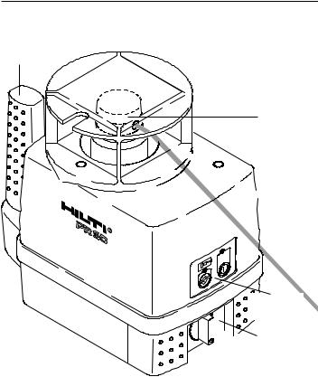
Description of the PR 60
Grip
Rotating head
Laser beam (invisible)
Control panel
 Battery compartment
PR 60 rotating laser - for quick and precise horizontal alignment 4

1. Product Information
Description of the PR 60, continued
The Hilti PR 60 is a rotating laser level with a rotating, invisible laser beam.
Features
-Using the PR 60 rotating laser, a single person can level any plane quickly and with great accuracy - always in conjunction with the PA 350 detector.
-The speed of rotation of the PR 60 is 600 rpm (revolutions per minute) when the tool is levelled.
-Automatic levelling (within ±5°):
Levelling takes place automatically after the tool is switched on by way of two built-in servo motors for the x and y axes. The beam switches on once the specified accuracy and full speed of rotation has been reached.
-The built-in liquid compensation system ensures high accuracy and optimum beam stabilisation over the entire service life of the unit.
-LEDs indicate the current operating status.
-Built-in shock warning function: The tool switches to warning mode should it be knocked off level during operation (vibration / impact); the auto-levelling and shock warning LEDs blink and the speed of rotation of the head is reduced to 150 rpm.
-Automatic cut-out: The laser beam does not switch on and the auto-levelling LED blinks when the tool is set up outside its self-levelling range or when rotation is blocked mechanically.
-The tool can be mounted on a tripod with 5/8” thread or placed directly on a steady supporting surface.
-Easy to operate, robust construction, reasonable weight.
5
1. Product Information
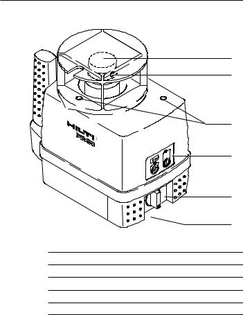
Main parts of the PR 60
1
2
3
4
5
6
No. Designation
1Rotating head
2Laser exit aperture
3Adjustment apertures
4Control panel
5Battery compartment with locking knob
6Baseplate with grip and 5/8" thread
6

|
|
|
|
|
|
|
|
|
|
|
|
|
|
|
1. Product Information |
|
|
|
|
|
|
|
|
|
|
|
|
|
|
|
|
|
|
PR 60 control panel |
|
|
|
|
|
|
|
|
|
|
|
|
|
|
||
5 |
|
|
|
|
|
|
|
|
|
|
|
|
|
|
|
1 |
|
|
|
|
|
|
|
|
|
|
|
||||||
4 |
|
|
|
|
|
|
|
|
|
|
|
|
|
|
|
2 |
|
|
|
|
|
|
|
|
|
|
|
|
|
|
|
||
|
|
|
|
|
|
|
|
|
|
|
|
|
|
|
||
3 |
|
|
|
|
|
|
|
|||||||||
|
|
|
|
|
|
|
|
|
|
|
|
|
|
|
||
No. Designation
1Auto-levelling LED
2ON / OFF button
3Shock warning ON / OFF button
4Shock warning LED
5Battery capacity LED
ON / OFF button
For switching the tool on / off. After switching on, the tool begins the automatic levelling process and the auto-levelling LED blinks. Battery capacity is also indicated.
Auto-levelling LED |
|
Blinking rapidly |
automatic levelling started |
|
|
Blinking slowly |
levelling almost complete |
|
|
Off |
tool is levelled / operating correctly |
|
|
7

1. Product Information
PR 60 control panel, continued
Shock warning LED
During operation, the tool monitors its own steady position. The laser switches off and the tool indicates a warning should it suddenly be brought out of level due to vibration or an impact:
 The auto-levelling LED and shock warning LED blink rapidly.
The shock warning LED lights continuously (red) when the shock warning function has been deactivated.
Shock warning button
-The shock warning function is activated each time after the tool is switched on and levelling has been achieved.
-To deactivate the shock warning function, press the button twice in quick succession. The shock warning LED then lights continuously (Red).
-The shock warning function can be reactivated by pressing the button once or switching the tool on again. The LED then no longer lights.
CAUTION
It is possible that no shock warning is given if the height of the tripod drops very slowly and parallel to the level at which it was set. The level should thus be checked at regular intervals.
8

1. Product Information
PR 60 control panel, continued
Battery capacity LED
In order to save battery power, the battery capacity LED is active for approx. 1 minute only after switching on the tool and after a change in the information indicated (change in remaining battery capacity).
Indication of remaining battery capacity (in 4 stages)
- All LEDs light:
Maximum battery capacity (4.6 V or more)
- 2 LEDs light:
Between 4.0 and 4.6 V
- 1 LED blinks:
3.3 to 4.0 V: The tool may continue to be operated for only a short time; replace the batteries.
- The LEDs blink alternately as long as some voltage is still available:
Batteries exhausted: The tool no longer operates.
9

1. Product Information
PR 60 quick-start instructions
1.Set up the tripod (e.g. PA 910) on a steady, approximately horizontal surface. Take care to ensure that as many measuring points as possible can be reached.
2.Mount the PR 60 correctly on the tripod.
3.Switch on the tool.
The auto-levelling LED blinks, the shock warning function is activated and the remaining battery capacity indicated. Levelling takes place automatically (under the most unfavourable conditions, within 90 sec.), the auto-levelling LED extinguishes and the head begins to rotate at the operating speed of 600 rpm.
The laser beam does not switch on and the auto-levelling LED blinks when the tool is set up outside its self-levelling range (±5°) or when rotation is blocked mechanically.
To remedy this, proceed as follows:
-Switch off the PR 60
-Level the tripod approximately by hand
-Switch on the PR 60 again
4.Attach the PA 350 detector correctly to the surveyor’s rod. Switch on the detector and begin work.
When working in an unsteady environment (vibration, wind,...), it may be of advantage to switch off the PR 60’s shock warning function. In this case, however, unintentional displacement of the tool will be ignored. The tool then relevels itself automatically. The level should thus be checked at regular intervals.
10
1. Product Information
PR 60 technical data
Measurement range
1 - 150 m [500 ft] (radius) with PA 350 detector
Accuracy ± 0.7 mm @ 10 m (at 24°C) [± 0.028 inch @ 32.8 ft]
Speed of rotation [600 rpm]
600 rpm (operating speed)
Laser |
Invisible, 795 nm (laser class 1) (EN60825-1) |
|
|
Class I (FDA21 CFR); output power: < 1mW |
|
Levelling |
|
|
Self-levelling within ±5°, LED indicator |
||
|
Operating indicators
-auto-levelling LED
-battery condition LED
-shock warning LED
Shock warning
When the tool is brought out of level during operation as a result of an impact or vibration:
-rotation stops
-the auto-levelling and shock warning LEDs both blink
Power supply
4 type-D alkaline batteries (standard) or
4 type-D NiCd rechargeable batteries (in conjunction with the accessory charger set)
11

1. Product Information
PR 60 technical data, continued
Battery life at 20°C [+68°F]
Alkaline: > 140 h
Ni-Cd: > 60 h
Tripod thread
5/8 " x 11
Operating temperature
-20° ... +50°C [-4°F ... +122°F]
Storage temperature
-30° ... +60°C dry [-22°F ... +140°F]
Protection class
IP 56 (IEC 529),
Protection against dust and heavy water spray
Weight |
3.0 kg (6.6 lbs) including 4 batteries |
Dimensions
260(L) x 151(W) x 242(H) mm [10.2(L) x 5.9(W) x 9.5(H) inches]
12

1. Product Information
PR 60 technical data, continued
Dimensions [mm]
242.4
260
35
28
151.3 |
13
1. Product Information
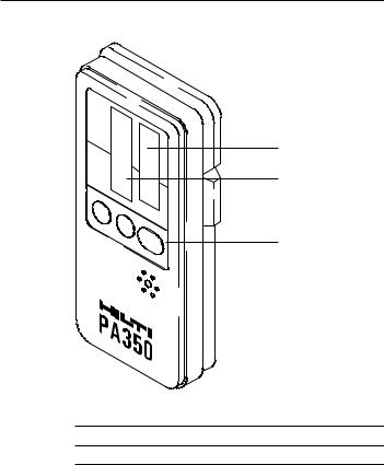
Description of the PA 350
1 |
2 |
3 |
No. Designation
1Display (front)
2Detection window
3Control panel
14

1. Product Information
Description of the PA 350, continued
The Hilti PA 350 detector is designed to detect the laser beam emitted by rotating lasers.
Features
-When a laser beam strikes the detection window, a liquid crystal display indicates whether the detector lies below, above or exactly in the reference plane (at the height of the mark).
-The visual indicators (arrows) and acoustic signal help the user to find the reference plane.
-The detector can be used on its own or it may be mounted on the telescopic rod or attached to a wooden batten or frame etc. using a suitable holder.
-To assist in finding the laser plane, one of two laser plane indicator area widths (narrow or standard) may be selected. A bar is shown in the display when the laser plane is within these areas. (Please refer to the section on “Compensation”.)
-Automatic cut-out
Battery power is switched off automatically when no laser beam is detected over a period of more than approx. 30 minutes.
-Indicates the status of the PR60: The PA 350 detects the warnings transmitted by the PR 60 and indicates «shock warning» as well as «low batteries».
15
 Loading...