


7 |
8 |
Hilti Corporation
LI-9494 Schaan
Tel.: +423 / 234 21 11
Fax: +423 / 234 29 65
www.hilti.com
Hilti = registered trademark of Hilti Corp., Schaan W 3399 0307 00-Pos. 2 1 Printed in Liechtenstein © 2007 |
320299 / B |
*320299* |
320299 |
|
|
|
|
||
Right of technical and programme changes reserved S. E. & O. |
|
|
|
|
|
|
|
|
|
|
|
|
|
|
PD 42
Operating instructions |
en |
Brugsanvisning |
da |
Bruksanvisning |
sv |
Bruksanvisning |
no |
Käyttöohje |
fi |
Инструкция по зксплуатации |
ru |
Lietoßanas pamåcîba |
lv |
Instrukcija |
lt |
Kasutusjuhend |
et |

1
+≠ |
+± +“ |
4 |
3 |
+Ç |
1 |
2 |
|
|
|
|
|
|
|
6 |
|
8 |
9 |
7 5 |
+# |
|
|
|
|
|
+| |
+{ |
|
+[ |
|
|
|
|
|
+] |
|
|
|
|
|
2 |
|
|
|
2 |
1 |
|
4 |
|
|
3 |
|
|
|
6 |
5 |
|
|
|
|
3 |
|
|
|
4 |
|
|
|
|
1 |
|
|
|
|
|
2 |
5 |
|
|
6 |
|
|
1 |
|
PD 42 laser range meter
It is essential that the operating instructions are read before the tool is operated for the first time.
Always keep these operating instructions together with the tool.
Ensure that the operating instructions are with the tool when it is given to other persons.
|
Contents |
Page |
||
|
1. |
General information |
25 |
|
|
2. |
Description |
26 |
|
|
3. |
Insert tools, accessories |
30 |
|
|
4. |
Technical data |
30 |
|
|
5. |
Safety rules |
31 |
|
|
6. |
Before use |
33 |
|
|
7. |
Operation |
37 |
|
|
8. |
Care and maintenance |
44 |
|
|
9. |
Troubleshooting |
45 |
|
|
10. |
Disposal |
46 |
|
|
11. |
Manufacturer’s warranty tools |
47 |
|
|
12. |
EC declaration of conformity |
47 |
|
1These numbers refer to the corresponding illustrations. The illustrations can be found on the fold out cover pages. Keep these pages open while studying
the operating instructions. en In these operating instructions, the designation “the
tool” always refers to the PD 42 laser range meter.
Parts, operating controls and indicators 1
@ On/off button
; Side measure button = Graphic display
% Measure button
& Delete (clear) button ( Horizontal bubble ) FNC button
+ Folding spike
§ {/ " thread for PDA 71 measuring extension / Rear contact points
: Minus button · Plus button
$ {/ " thread on the underside £ Reference button
| Optical sight ¡ Laser exit lens Q Receiving lens W Vertical bubble
1. General information
1.1 Safety notices and their meaning
DANGER
Draws attention to imminent danger that could lead to serious bodily injury or fatality.
WARNING
Draws attention to a potentially dangerous situation that could lead to serious personal injury or fatality.
CAUTION
Draws attention to a potentially dangerous situation that could lead to slight personal injury or damage to the equipment or other property.
NOTE
Draws attention to an instruction or other useful information.
1.2Explanation of the pictograms and other information
Warning signs
General warning
25
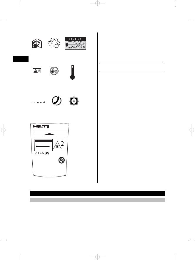
Symbols
|
Read the |
Return waste |
Laser class II according |
|
operating |
material for |
to CFR 21, § 1040 (FDA) |
en |
instructions |
recycling. |
|
before use. |
|
|
|
|
|
>1/4s |
|
|
Laser class 2 |
Do not look |
Temperature |
|
in accordance |
into the beam. |
indicator |
|
with |
|
|
|
EN 60825 |
|
|
|
1:2003 |
|
|
|
|
|
|
|
|
|
|
|
|
|
|
|
|
|
|
|
|
|
|
|
|
|
|
|
|
|
|
|
|
|
|
|
|
Battery status |
Hardware |
Unfavorable |
|||||||
|
|
indicator |
errors |
operating |
||||||
|
|
|
|
|
|
|
|
|
|
conditions |
Type identification plate
PD 42 01
Hilti = trademark of Hilti Corp., Schaan, LI Made in Germany
Serial number
AVOID EXPOSURE
Laser radiation is emitted from this aperture
LASER RADIATION - DO NOT
STARE INTO BEAM
620-690nm/0.95mW max. CLASS II LASER PRODUCT
DIN EN 60825-1:2003
This device complies with part 15 of the FCC Rules. (1) This device may not
cause harmful interference, and (2) this device must accept any inter-
ference received, including inter-
ference that may cause undesired operation.
Item No.: 30673 Power: 3V nom/400 mA
Manufactured:
PD 42
Location of identification data on the tool
The type designation and serial number can be found on the type identification plate on the tool. Make a note of this data in your operating instructions and always refer to it when making an enquiry to your Hilti representative or service department.
Type:
Serial no.:
2. Description
2.1 Use of the product as directed
The tool is designed for measuring distances, adding and subtracting distances and offers many practical functions such as a timer, area and volume measurement, min/max calculation, setting out, painter’s area measurement, Pythagoras function and data memory.
Do not use the tool as a leveling tool.
Measurements taken from plastic foam materials such as polystyrene foam, from snow or from highly reflective surfaces (mirrors, glass, etc.) may produce inaccurate results.
26

The tool and its ancillary equipment may present hazards when used incorrectly by untrained personnel or |
|
|
when used not as directed. |
|
|
Take the influences of the surrounding area into account. Do not use the appliance where there is a risk of fire |
|
|
or explosion. |
|
|
Observe the information printed in the operating instructions concerning operation, care and maintenance. |
|
|
To avoid the risk of injury, use only genuine Hilti accessories and additional equipment. |
|
|
Modification of the tool is not permissible. |
|
|
en |
||
NOTE |
|
|
Observe the permissible operating and storage temperatures. |
|
|
|
|
|
2.2 Display |
|
|
The measurements, settings and tool status are shown in the display. When the tool is in measuring mode, |
|
|
the measurements taken are shown at the bottom of the display area (the result line). When using a function, |
|
|
e.g. area measurement, the distances measured are shown in the intermediate result line and the calculated |
|
|
result is shown at the bottom of the display (the result line). |
|
|
|
|
|
2.3 Display illumination |
|
|
In low light conditions, the display is illuminated automatically as soon as a button is pressed. The display |
|
|
illumination intensity is reduced to 50% after 10 seconds. If no button is pressed over a period of 20 seconds, |
|
|
the display illumination switches off automatically. |
|
|
NOTE |
|
|
Illumination of the display consumes battery power. Shorter battery life is therefore to be expected when this |
|
|
feature is used frequently. |
|
|
|
|
|
2.4 Basic principle |
|
|
The distance is measured along a laser beam emitted by the tool to the point at which the beam strikes |
|
|
a reflective surface. The target from which the measurement is taken is clearly identified by the red laser |
|
|
measuring spot. The range of the tool depends on the reflectance and structure of the target surface from |
|
|
which measurements are taken. |
|
|
|
|
|
2.5 Measuring principle |
|
|
The tool emits a visible laser beam carrying signal pulses which are reflected by the target. The time between |
|
|
reflected pulses is used as a basis for determining the distance. |
|
|
This measuring principle permits highly accurate and reliable measurement of distances to objects without |
|
|
need for special reflectors. |
|
|
|
|
|
2.6 Standard measuring display mode |
|
|
Standard measuring display mode is always activated when the “On/off” or “Measure” button is pressed to |
|
|
switch the tool on. |
|
|
27
2.7 Symbols in the display
|
|
Temperature |
Temperature too high |
Allow the tool to cool down or warm up. |
|
|
|
(>+50°C) / too low (< |
|
|
|
|
10°C). |
|
|
|
Unfavorable operating |
Insufficient reflected |
Observe the minimum measuring distance (50 mm |
|
|
conditions |
laser light. |
from the front edge of the tool); clean the lenses; |
en |
|
|
take measurements from a different surface or use a |
|
|
|
|
|
target plate. |
|
|
|
|
|
|
|
|
|
|
|
|
General hardware error |
|
Switch the tool off and on again. If the fault persists, |
|
|
|
|
please contact Hilti Service. |
|
|
|
|
|
|
|
2.8 Control panel |
|
|
|
|
Measure button |
|
Activates the laser beam. |
|
|
|
|
|
|
|
|
|
Begins distance measurement. |
|
|
|
|
Activates continuous measuring mode (long press, |
|
|
|
|
approx. 2 sec.). |
|
|
|
|
Stops continuous measuring mode. |
|
|
Plus button |
|
Initiates distance, area and volume addition. |
|
|
|
|
Adds distances in standard measuring and painter’s |
|
|
|
|
measuring modes. |
|
|
|
|
|
|
|
|
|
Adds areas and volumes in the relevant modes. |
|
|
Minus button |
|
Initiates distance, area and volume subtraction. |
|
|
|
|
Subtracts distances in standard measuring and |
|
|
|
|
painter measuring modes. |
|
|
|
|
Subtracts areas and volumes in the relevant modes. |
|
|
FNC button |
|
Always activates the previously used function. |
|
|
|
|
Press the button repeatedly to activate or select the |
|
|
|
|
functions one after the other (when no measurements |
|
|
|
|
have been taken). |
|
|
|
|
When measurements have been taken: Deletes all |
|
|
|
|
measurements and restarts the function. |
|
|
|
|
Stops continuous measuring (tracking). |
|
|
Delete (clear) button |
The C button has various |
Stops continuous measuring (tracking). |
|
|
|
functions depending on |
|
|
|
|
operating mode. |
|
|
|
|
|
Clears the standard measurement display. |
|
|
|
|
Clears the last measurement and returns to |
|
|
|
|
“Functions”. |
|
|
|
|
Clears data memory (long press when data memory |
|
|
|
|
is displayed). |
|
|
|
|
Ends the function if no measurements have been |
|
|
|
|
taken. |
28

On/off button |
When the tool is switched off, press the button |
|
|
||
|
|
briefly to switch it on. |
|
|
|
|
|
When the tool is switched off, press and hold the |
|
|
|
|
|
button to activate the menu. |
|
|
|
|
|
When the tool is switched on, press the button |
|
|
|
|
|
briefly to switch it off. |
|
|
|
Reference button |
Switches between the various measuring reference |
|
en |
||
|
|
points (front, tripod thread on the underside, rear). |
|
|
|
|
|
|
|
||
|
|
|
|
|
|
2.9 Battery condition indicator |
|
|
|
|
|
Number of segments shown |
|
Charge status in % |
|
|
|
|
|
|
|||
|
|
|
|
|
|
4 |
|
|
= 100 % capacity |
|
|
3 |
|
|
= 75 % capacity |
|
|
2 |
|
|
= 50 % capacity |
|
|
1 |
|
|
= 25 % capacity |
|
|
0 |
|
|
Fully discharged |
|
|
2.10 Items supplied as standard
1PD 42 laser range meter
1Hand strap
1PDA 50 target plate
2Batteries
1Battery compartment key
1Operating instructions
1Manufacturer’s certificate
2.11PUA 60 laser visibility glasses
The laser visibility glasses have no protective function and thus do not protect the eyes from laser beams. As these glasses limit color vision they must not be worn by persons driving on a public road and must not be used to look directly into the sun.
The PUA 60 laser visibility glasses improve laser beam visibility considerably.
2.12 PDA 50 / 51 / 52 target plate
The PDA 50 target plate is made of durable plastic with a special reflective coating. Use of the target plate is recommended at distances greater than 10 m in poor light conditions.
The PDA 51 target plate has no reflective coating and its use is recommended in poor light conditions and at short distances. The PDA 52 target plate is equipped with the same reflective coating as the PDA 50 but is considerably larger in size (A4 format, 210 x 297 mm). This makes it much easier to aim the tool at the target plate over long distances.
NOTE
For reliable distance measurements, care should be taken to ensure that the laser beam strikes the target plate at right angles as far as possible. The laser spot on the target plate and the measuring reference point (starting point) may otherwise be in different planes (parallax error).
29

NOTE
When the target plate is used and very high accuracy is required, 1.2 mm should be added to the measurement obtained.
2.13 PDA 71 measuring extension
The measuring extension is made from aluminium and is equipped with a non conductive plastic grip. The en screw on the measuring extension should be screwed into the threaded bush on the rear contact surface of the PD 42. When the measuring extension is screwed onto the tool, the rear reference is then relocated to the
tip of the measuring extension, i.e. the rear reference is extended by 1270 mm (50 inches).
3. Insert tools, accessories
Target plate |
PDA 50 |
Target plate |
PDA 51 |
Target plate |
PDA 52 |
Measuring extension |
PDA 71 |
Hand strap |
PDA 60 |
|
|
Soft pouch |
PDA 65 |
Laser visibility glasses |
PUA 60 |
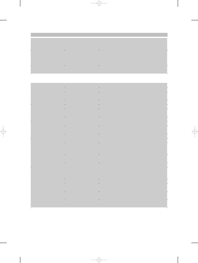
4. Technical data
Right of technical changes reserved. |
|
|
Technical data |
|
Values |
|
||
|
|
|
Power supply |
|
3V DC AA size batteries |
Battery condition check |
|
Battery condition indicator with 4 segments showing |
|
|
100%, 75%, 50%, 25% charge : No segments |
|
|
shown: The batteries are exhausted |
Measuring range |
|
0.05…200 m |
Typical measuring range without target plate |
|
Drywall panel, white: 100 m |
|
|
Concrete, dry: 70 m |
|
|
Brick, dry: 50 m |
|
|
|
Accuracy |
|
Typically ±1.0 mm for single and continuous |
|
|
measurement |
Smallest unit displayed |
|
1 mm |
Beam diameter |
|
Beam length 10 m: Max. 6 mm |
|
|
Beam length 50 m: Max. 30 mm |
|
|
Beam length 100 m: Max. 60 mm |
|
|
|
Basic operating modes |
|
Single measuring, continuous measuring, calcula- |
|
|
tion/functions |
|
|
|
Display |
|
Illuminated dot matrix display with permanent |
|
|
indication of operating mode and battery condition |
30
 Loading...