


Ferroscan System FS10
Bedienungsanleitung Operating instructions
Contents |
Main functions |
|
|
1. Safety / care and maintenance . . . . . . . . . . . . . . . . . . . . . . . . . . . . . . . . . . . . . . . . . 17
2. Items supplied. . . . . . . . . . . . . . . . . . . . . . . . . . . . . . . . . . . . . . . . . . . . . . . . . . . . . . 18
3. |
Preparing the system for operation . . . . . . . . . . . . . . . . . . . . . . . . . . . . . . . . . . . . . |
18 |
4. Operation . . . . . . . . . . . . . . . . . . . . . . . . . . . . . . . . . . . . . . . . . . . . . . . . . . . . . . . . . . 19 4.1 RV10 monitor . . . . . . . . . . . . . . . . . . . . . . . . . . . . . . . . . . . . . . . . . . . . . . . . . . . . . . . 19 Operating controls . . . . . . . . . . . . . . . . . . . . . . . . . . . . . . . . . . . . . . . . . . . . . . . . . . . . 19 Function keys . . . . . . . . . . . . . . . . . . . . . . . . . . . . . . . . . . . . . . . . . . . . . . . . . . . . . . . 19 Display . . . . . . . . . . . . . . . . . . . . . . . . . . . . . . . . . . . . . . . . . . . . . . . . . . . . . . . . . . . . 19 4.2 RS10 scanner . . . . . . . . . . . . . . . . . . . . . . . . . . . . . . . . . . . . . . . . . . . . . . . . . . . . . . . 20
4.3 Paper reference grid and ruler . . . . . . . . . . . . . . . . . . . . . . . . . . . . . . . . . . . . . . . . . . . 20 4.4 TCU12 H charger . . . . . . . . . . . . . . . . . . . . . . . . . . . . . . . . . . . . . . . . . . . . . . . . . . . . . 21 4.5 RB10 battery . . . . . . . . . . . . . . . . . . . . . . . . . . . . . . . . . . . . . . . . . . . . . . . . . . . . . . . 22
5. Using the system. . . . . . . . . . . . . . . . . . . . . . . . . . . . . . . . . . . . . . . . . . . . . . . . . . . . 23 5.1 Setup . . . . . . . . . . . . . . . . . . . . . . . . . . . . . . . . . . . . . . . . . . . . . . . . . . . . . . . . . . . . . 23 5.2 Scanning an image . . . . . . . . . . . . . . . . . . . . . . . . . . . . . . . . . . . . . . . . . . . . . . . . . . . 23 5.3 Determination of position, coverage and diameter of reinforcement . . . . . . . . . . . . . . . . 25 5.4 Rapid detection and verification of minimum coverage . . . . . . . . . . . . . . . . . . . . . . . . .26 5.5 Identifying, recalling and printing images . . . . . . . . . . . . . . . . . . . . . . . . . . . . . . . . . . .27 5.6 PC software . . . . . . . . . . . . . . . . . . . . . . . . . . . . . . . . . . . . . . . . . . . . . . . . . . . . . . . . .27
6. Working range. . . . . . . . . . . . . . . . . . . . . . . . . . . . . . . . . . . . . . . . . . . . . . . . . . . . . . 28
7. Ferroscan FS10 system - technical data. . . . . . . . . . . . . . . . . . . . . . . . . . . . . . . . . . 29
8. Warranty . . . . . . . . . . . . . . . . . . . . . . . . . . . . . . . . . . . . . . . . . . . . . . . . . . . . . . . . . . 29
The Ferroscan FS10 system provides the following main functions:
●Rapid detection and verification of minimum concrete coverage (see section 5.4).
●Scanning and recording of images, with determination of depth of coverage and diameter of reinforcement (see sections 5.2 and 5.3).
●Printing out of images (see section 5.5).
●PC software for data evaluation (see section 5.6)
Right of technical modifications reserved
16

1. Safety / care and maintenance
Safety precautions Ferroscan System |
Safety precautions TCU12 H |
||
|
|
Important: The following safety precautions must be |
|
Important: The following safety precautions must be |
|
||
|
observed |
||
observed |
|
||
|
● The mains supply must correspond to the information printed |
||
● A qualified technical expert (e.g. civil engineer) must be |
|
||
|
on the rating plate. 230 volt units may also be connected to a |
||
consulted when making use of the measurement data for |
|
||
|
220 volt supply. |
||
safety relevant purposes (e.g. structural design). |
|
||
|
● Only Hilti RB10 batteries should be charged using this char- |
||
|
|
||
Care and maintenance |
ger. |
||
The TCU12H charger and RB10 battery have been designed to |
|||
The Ferroscan FS10 system is a testing instrument. Although it |
|||
work together optimally. |
|||
has been designed for arduous jobsite conditions (impact and |
|||
● The charger must be able to give off heat during the charg- |
|||
vibration resistance) it should be treated with the appropriate |
ing procedure. Please ensure that the ventilation slits are not |
||
care. |
|||
obstructed. |
|||
The LCD display is suitable for operation in temperatures within |
|||
Do not use the charger in closed containers! |
|||
the range –10°C % to % +50°C. Extreme temperatures result- |
|||
● Do not short circuit the contacts. |
|||
ing from exposure to direct sunlight for long periods and other |
● The charger should be located in a dry, clean and cool place |
||
sources of heat such as radiators should be avoided! |
but protected from frost. |
||
The PC and printer connections should always be covered when |
|||
As this unit is connected to the mains supply, safety precautions |
|||
not in use in order to protect the instrument from the effects of |
|||
must be observed. |
|||
dust and water spray. |
|||
|
|||
The RS10 scanner required to be recalibrated after a period of |
Care and maintenance |
||
use of approx. two years. It is recommended that the RS10 |
|||
Always disconnect the mains plug from the mains supply before |
|||
scanner is returned to the nearest Hilti centre for recalibration |
|||
cleaning or servicing the TCU12 H. The contacts in the battery |
|||
after a period of two years. If the measurement characteristics |
|||
compartment must be kept clean (free of oil and grease). |
|||
lie outside tolerance limits, the complete system becomes inop- |
The ventilation slits must be free of dirt and dust. |
||
erative. No further readings can be taken. |
|||
A damaged supply cord must be replaced by a Hilti repair cen- |
|||
The lithium auxiliary battery has a life of approx. six years. It is |
|||
tre, as special tools are required for carrying out the repair cor- |
|||
recommended that this battery is checked at the two-yearly cal- |
|||
rectly. |
|||
ibration intervals. |
|||
|
|||
Safety precautions RB1O
Important: The enclosed safety precautions must be observed
●Before operating the unit, check that the RB10 battery has been fitted securely.
●Do not continue to operate the unit until the RB10 battery becomes totally exhausted (unit completely inoperative). The battery cells may suffer damage if completely discharged.
●The BP10 battery should be stored in a dry place and protected from frost. Heat sources such as direct sunlight or radiators should be avoided.
●The RB10 battery should be used only in the units indicated by Hilti. Use only the charger specified by Hilti for charging the RB10 battery. The charger, battery and other units of the system are designed to work together optimally.
●If necessary, clean the RB10 battery terminals before inserting it into the charger or into the unit.
●Do not short circuit the RB10 battery terminals.
●New RB10 batteries or batteries which have not been used for a long period only reach full capacity after several charge/discharge cycles.
Care and maintenance
Battery terminals must be kept clean (free of oil and grease). If, after having been subjected to considerable use, battery capacity drops below an acceptable level, we recommend that the battery is checked by Hilti.
Important: RB10 batteries which have reached the end of their life should be returned to Hilti for recycling.
17
2. Items supplied |
3. Preparing the system for operation |
|
|
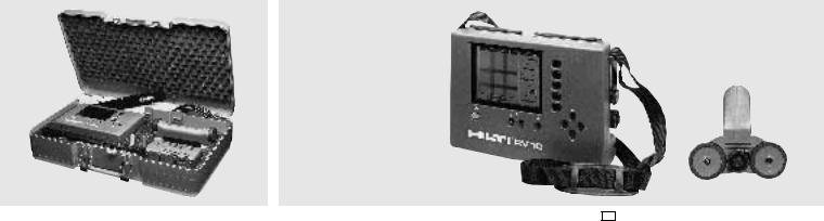
The Ferroscan FS10 system is supplied in a standard impactresistant Hilti case. The case contains:
1 RV10 monitor (evaluation module)
1 RS10 scanner (detection probe)
1 RC10 connecting cable
1 RB10 battery
1 TCU12 H charger
10 RG10 paper reference grids
1 roll of adhesive tape
1 serial interface connecting cable
1 PC program for data analysis
Before the system can be operated, the RB10 battery must be charged using the TCU12 H charger (see section 4.4).
The charged RB10 battery should be inserted in the compartment on the base of the RV10 monitor (locking lever facing upwards).
Press the I/O button to switch on the RV10 monitor. If the system is being operated for the first time, after running through an automatic self test, a short description of basic functions appears on the screen. Alternatively, the last recorded image will appear on the screen. The battery must be recharged when the  symbol, which appears at the left-hand edge of the screen, begins to blink. Charge the battery using the TCU12 H charger (see page 21). The RS10 scanner must be connected to the RV10 monitor using the RC10 connecting cable before readings can be taken.
18

4. Operation
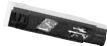
4.1 RV10 monitor
7 |
8 |
9 |
12 |
|||
|
|
|
|
|
|
|
|
|
|
|
|
|
|
6
 10
10
5
1
11
2 3 4
Operating controls
1 On/off button
2 Increase image contrast
3 Reduce image contrast
4Print
5Cursor keys
6Function keys
7Printer connection
8PC connection
9DC power supply socket
10Scanner connection
11Battery compartment
12Carrying strap
Warning: for DC power supply a regulated output voltage of 12 V is required.
Note: To save battery power, the monitor switches off automatically if no button is pressed for a period of 5 minutes.
1254 22-OCT-92 09:35
25 of 26
Main Menu
Scan...
Analyse...
Quickscan...
Delete
Image...
Set Up...
Function keys
The five function keys are used to select a function from the main menu which appears on the right-hand side of the screen. When a function has been selected, the function menu is displayed. If no function is allocated to a particular key, the corresponding position on the screen remains blank. If a function is not available for a particular operating mode, the menu position is displayed in grey.
To return to the main menu from a function menu, press the
Done key.
"Scan"creates and stores a 600mm square image. Up to 42 images can be stored.
"Analyse"provides detailed measurement functions for the stored images.
"Quickscan"gives rapid assesment of coverage over a large surface.
"Delete image"removes one or more images from the memory.
"Set up"sets volume, time, date and language.
Main Menu
Scan...
Analyse...
Quickscan...
Delete
Image...
Set Up...
Display
Normally, when the RV10 monitor is switched on, the last recorded image appears on the screen. If no image is stored in the RV10's memory, a brief description of the main functions is displayed.
19
 Loading...