


Network Video Recorder
Quick Start Guide
UD00615B

Network Video Recorder Quick Start Guide
TABLE OF CONTENTS
Chapter1 Panels Description........................................................................................................................... |
7 |
||
1.1 |
Front Panel ...................................................................................................................................... |
7 |
|
|
1.1.1 |
DS-9600NI Series ............................................................................................................... |
7 |
|
1.1.2 |
DS-8600NI and DS-7700NI Series..................................................................................... |
9 |
|
1.1.3 |
DS-7600NI Series ............................................................................................................. |
11 |
1.2 |
Rear Panel ..................................................................................................................................... |
11 |
|
|
1.2.1 |
DS-9600NI and DS-8600NI Series................................................................................... |
11 |
|
1.2.2 |
DS-7700NI Series ............................................................................................................. |
12 |
|
1.2.3 |
DS-7600NI Series ............................................................................................................. |
13 |
Chapter 2Installation and Connections........................................................................................................ |
15 |
||
2.1 |
NVR Installation............................................................................................................................ |
15 |
|
2.2 |
Hard Disk Installation.................................................................................................................... |
15 |
|
|
2.2.1 |
DS-9600NI Series ............................................................................................................. |
15 |
|
2.2.2 |
Other Models .................................................................................................................... |
17 |
2.3 |
Connections ................................................................................................................................... |
19 |
|
|
2.3.1 |
Alarm Input Wiring........................................................................................................... |
19 |
|
2.3.2 |
Alarm Output Wiring ........................................................................................................ |
19 |
|
2.3.3 |
Using Alarm Connectors................................................................................................... |
19 |
|
2.3.4 |
Controller Connection....................................................................................................... |
20 |
2.4 |
HDD Storage Calculation Chart .................................................................................................... |
21 |
|
Chapter 3Menu Operation ............................................................................................................................ |
22 |
||
3.1 |
Menu Structure .............................................................................................................................. |
22 |
|
3.2 |
Startup and Shutdown.................................................................................................................... |
22 |
|
3.3 |
Activating Your Device ................................................................................................................. |
23 |
|
3.4 |
Using the Unlock Pattern for Login............................................................................................... |
24 |
|
3.5 |
Login and Logout .......................................................................................................................... |
25 |
|
|
3.5.1 |
User Login ........................................................................................................................ |
25 |
|
3.5.2 |
User Logout ...................................................................................................................... |
26 |
3.6 |
Using the Setup Wizard ................................................................................................................. |
26 |
|
3.7 |
Network Settings ........................................................................................................................... |
27 |
|
3.8 |
Adding IP Cameras........................................................................................................................ |
27 |
|
3.9 |
Live View ...................................................................................................................................... |
28 |
|
3.10 |
One-Touch RAID Configuration ................................................................................................... |
29 |
|
3.11 |
Recording Settings......................................................................................................................... |
30 |
|
3.12 |
Playback ........................................................................................................................................ |
30 |
|
Chapter 4Accessing by Web Browser........................................................................................................... |
32 |
||
1

Network Video Recorder Quick Start Guide
Quick Start Guide
COPYRIGHT ©2016 Hangzhou Hikvision Digital Technology Co., Ltd.
ALL RIGHTS RESERVED.
Any and all information, including, among others, wordings, pictures, graphs are the properties of Hangzhou Hikvision Digital Technology Co., Ltd. or its subsidiaries (hereinafter referred to be “Hikvision”). This user manual (hereinafter referred to be “the Manual”) cannot be reproduced, changed, translated, or distributed, partially or wholly, by any means, without the prior written permission of Hikvision. Unless otherwise stipulated, Hikvision does not make any warranties, guarantees or representations, express or implied, regarding to the Manual.
About this Manual
This Manual is applicable to Network Video Recorder (NVR).
The Manual includes instructions for using and managing the product. Pictures, charts, images and all other information hereinafter are for description and explanation only. The information contained in the Manual is subject to change, without notice, due to firmware updates or other reasons. Please find the latest version in the company website (http://overseas.hikvision.com/en/).
Please use this user manual under the guidance of professionals.
Trademarks Acknowledgement
and other Hikvision’s trademarks and logos are the properties of Hikvision in various jurisdictions.
Other trademarks and logos mentioned below are the properties of their respective owners.
Legal Disclaimer
TO THE MAXIMUM EXTENT PERMITTED BY APPLICABLE LAW, THE PRODUCT DESCRIBED, WITH
ITS HARDWARE, SOFTWARE AND FIRMWARE, IS PROVIDED “AS IS”, WITH ALL FAULTS AND
ERRORS, AND HIKVISION MAKES NO WARRANTIES, EXPRESS OR IMPLIED, INCLUDING WITHOUT LIMITATION, MERCHANTABILITY, SATISFACTORY QUALITY, FITNESS FOR A PARTICULAR PURPOSE, AND NON-INFRINGEMENT OF THIRD PARTY. IN NO EVENT WILL HIKVISION, ITS DIRECTORS, OFFICERS, EMPLOYEES, OR AGENTS BE LIABLE TO YOU FOR ANY SPECIAL, CONSEQUENTIAL, INCIDENTAL, OR INDIRECT DAMAGES, INCLUDING, AMONG OTHERS, DAMAGES FOR LOSS OF BUSINESS PROFITS, BUSINESS INTERRUPTION, OR LOSS OF DATA OR DOCUMENTATION, IN CONNECTION WITH THE USE OF THIS PRODUCT, EVEN IF HIKVISION HAS BEEN ADVISED OF THE POSSIBILITY OF SUCH DAMAGES.
REGARDING TO THE PRODUCT WITH INTERNET ACCESS, THE USE OF PRODUCT SHALL BE WHOLLY AT YOUR OWN RISKS. HIKVISION SHALL NOT TAKE ANY RESPONSIBILITES FOR ABNORMAL OPERATION, PRIVACY LEAKAGE OR OTHER DAMAGES RESULTING FROM CYBER ATTACK, HACKER ATTACK, VIRUS INSPECTION, OR OTHER INTERNET SECURITY RISKS; HOWEVER, HIKVISION WILL PROVIDE TIMELY TECHNICAL SUPPORT IF REQUIRED.
SURVEILLANCE LAWS VARY BY JURISDICTION. PLEASE CHECK ALL RELEVANT LAWS IN YOUR JURISDICTION BEFORE USING THIS PRODUCT IN ORDER TO ENSURE THAT YOUR USE CONFORMS THE APPLICABLE LAW. HIKVISION SHALL NOT BE LIABLE IN THE EVENT THAT THIS PRODUCT IS USED WITH ILLEGITIMATE PURPOSES.
IN THE EVENT OF ANY CONFLICTS BETWEEN THIS MANUAL AND THE APPLICABLE LAW, THE LATER PREVAILS.
2
Network Video Recorder Quick Start Guide
Regulatory Information
FCC Information
FCC compliance: This equipment has been tested and found to comply with the limits for a Class A digital device, pursuant to part 15 of the FCC Rules. These limits are designed to provide reasonable protection against harmful interference when the equipment is operated in a commercial environment. This equipment generates, uses, and can radiate radio frequency energy and, if not installed and used in accordance with the instruction manual, may cause harmful interference to radio communications. Operation of this equipment in a residential area is likely to cause harmful interference in which case the user will be required to correct the interference at his own expense.
FCC Conditions
This device complies with part 15 of the FCC Rules. Operation is subject to the following two conditions:
1.This device may not cause harmful interference.
2.This device must accept any interference received, including interference that may cause undesired operation.
EU Conformity Statement
This product and - if applicable - the supplied accessories too are marked with "CE" and comply therefore with the applicable harmonized European standards listed under the EMC Directive
2004/108/EC, the RoHS Directive 2011/65/EU.
2012/19/EU (WEEE directive): Products marked with this symbol cannot be disposed of as unsorted municipal waste in the European Union. For proper recycling, return this product to your local supplier upon the purchase of equivalent new equipment, or dispose of it at designated collection
points. For more information see: www.recyclethis.info
2006/66/EC (battery directive): This product contains a battery that cannot be disposed of as unsorted municipal waste in the European Union. See the product documentation for specific battery information. The battery is marked with this symbol, which may include lettering to indicate cadmium (Cd), lead (Pb), or mercury (Hg). For proper recycling, return the battery to your supplier or to a
designated collection point. For more information see: www.recyclethis.info
Industry Canada ICES-003 Compliance
This device meets the CAN ICES-3 (A)/NMB-3(A) standards requirements.
3

Network Video Recorder Quick Start Guide
Safety Instruction
These instructions are intended to ensure that user can use the product correctly to avoid danger or property loss.
The precaution measure is divided into “Warnings” and “Cautions”
Warnings: Serious injury or death may occur if any of the warnings are neglected.
Cautions: Injury or equipment damage may occur if any of the cautions are neglected.
|
|
|
|
|
|
Warnings |
Follow |
these |
Cautions |
Follow |
these |
safeguards to |
prevent |
serious |
precautions |
to |
prevent |
injury or death. |
|
|
potential injury or |
material |
|
|
|
|
damage. |
|
|
|
|
|
|
|
|
Warnings
●Proper configuration of all passwords and other security settings is the responsibility of the installer and/or end-user.
●In the use of the product, you must be in strict compliance with the electrical safety regulations of the nation and region. Please refer to technical specifications for detailed information.
●Input voltage should meet both the SELV (Safety Extra Low Voltage) and the Limited Power Source with 100~240 VAC or 12 VDC according to the IEC60950-1 standard. Please refer to technical specifications for detailed information.
●Do not connect several devices to one power adapter as adapter overload may cause over-heating or a fire hazard.
●Please make sure that the plug is firmly connected to the power socket.
●If smoke, odor or noise rise from the device, turn off the power at once and unplug the power cable, and then please contact the service center.
Preventive and Cautionary Tips
Before connecting and operating your device, please be advised of the following tips:
Ensure unit is installed in a well-ventilated, dust-free environment.
Unit is designed for indoor use only.
Keep all liquids away from the device.
Ensure environmental conditions meet factory specifications.
Ensure unit is properly secured to a rack or shelf. Major shocks or jolts to the unit as a result of dropping it may cause damage to the sensitive electronics within the unit.
Use the device in conjunction with an UPS if possible.
Power down the unit before connecting and disconnecting accessories and peripherals.
A factory recommended HDD should be used for this device.
Improper use or replacement of the battery may result in hazard of explosion. Replace with the same or equivalent type only. Dispose of used batteries according to the instructions provided by the battery manufacturer.
4

Network Video Recorder Quick Start Guide
Applicable Models
This manual is applicable to the models listed in the following table.
|
Series |
|
Model |
|
|
|
DS-9608NI-I8 |
|
|
|
|
|
DS-9600NI-I8 |
|
DS-9616NI-I8 |
|
|
DS-9632NI-I8 |
|
|
|
|
|
|
|
|
DS-9664NI-I8 |
|
|
|
DS-9616NI-I16 |
|
DS-9600NI-I16 |
|
DS-9632NI-I16 |
|
|
|
DS-9664NI-I16 |
|
|
|
DS-7608NI-I2 |
|
DS-7600NI-I2 |
|
DS-7616NI-I2 |
|
|
|
DS-7632NI-I2 |
|
|
|
DS-7608NI-I2/8P |
|
DS-7600NI-I2/P |
|
DS-7616NI-I2/16P |
|
|
|
DS-7632NI-I2/16P |
|
|
|
DS-7708NI-I4 |
|
DS-7700NI-I4 |
|
DS-7716NI-I4 |
|
|
|
DS-7732NI-I4 |
|
|
|
DS-7708NI-I4/8P |
|
DS-7700NI-I4/P |
|
DS-7716NI-I4/16P |
|
|
|
DS-7732NI-I4/16P |
|
|
|
DS-8608NI-K8 |
|
DS-8600NI-K8 |
|
DS-8616NI-K8 |
|
|
|
DS-8632NI-K8 |
|
|
|
DS-7708NI-K4 |
|
DS-7700NI-K4 |
|
DS-7716NI-K4 |
|
|
|
DS-7732NI-K4 |
|
|
|
DS-7708NI-K4/8P |
|
DS-7700NI-K4/P |
|
DS-7716NI-K4/16P |
|
|
|
DS-7732NI-K4/16P |
|
|
|
DS-7608NI-K2 |
|
DS-7600NI-K2 |
|
DS-7616NI-K2 |
|
|
|
DS-7632NI-K2 |
|
|
|
DS-7608NI-K2/8P |
|
DS-7600NI-K2/P |
|
DS-7616NI-K2/16P |
|
|
|
DS-7632NI-K2/16P |
|
|
|
DS-7604NI-K1 |
|
DS-7600NI-K1 |
|
DS-7608NI-K1 |
|
|
|
DS-7616NI-K1 |
|
DS-7600NI-K1/4P |
|
DS-7604NI-K1/4P |
5

Network Video Recorder Quick Start Guide
Symbol Conventions
The symbols that may be found in this document are defined as follows.
Symbol Description
Indicates a potentially hazardous situation, which if not avoided, could result in equipment damage, data loss, performance degradation, or unexpected results.
Provides additional information to emphasize or supplement important points of the main text.
6
Network Video Recorder Quick Start Guide
Chapter1 Panels Description
1.1 Front Panel
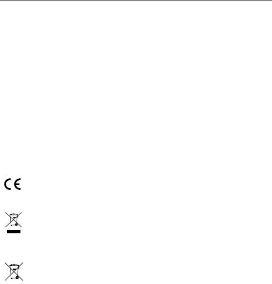
1.1.1 DS-9600NI Series
Figure 1. 1 DS-9600NI-I8 Series
Figure 1. 2 DS-9600NI-I16 Series
Table 1. 1 Panel Description
|
No. |
|
|
|
Name |
|
|
Function Description |
|
|
|
|
|
|
|
|
|
||||
|
|
|
|
|
|
ALARM |
|
Turns red when a sensor alarm is detected. |
||
|
|
|
|
|
|
READY |
|
Turns blue when the device is functioning properly. |
||
|
|
|
|
|
|
|
|
|
Turns blue when device is controlled by an IR remote. |
|
|
|
|
|
|
|
STATUS |
|
|
|
|
|
|
|
|
|
|
|
Turns red when controlled by a keyboard and purple when IR |
|||
|
|
|
|
|
|
|
|
|
||
|
1 |
|
|
Status |
|
|
|
|
remote and keyboard is used at the same time. |
|
|
|
|
Indicators |
|
HDD |
|
Flickers red when data is being read from or written to HDD. |
|||
|
|
|
|
|
|
|||||
|
|
|
|
|
|
MODEM |
|
Reserved for future usage. |
||
|
|
|
|
|
|
Tx/Rx |
|
Flickers blue when network connection is functioning properly. |
||
|
|
|
|
|
|
|
|
|
|
|
|
|
|
|
|
|
GUARD |
|
Turns blue when the device is in armed status; at this time, an |
||
|
|
|
|
|
|
|
alarm is enabled when an event is detected. |
|||
|
|
|
|
|
|
|
|
|
||
7
|
|
|
|
|
|
|
Network Video Recorder Quick Start Guide |
||||
|
|
|
|
|
|
|
|
|
|
|
|
|
|
No. |
|
|
|
Name |
|
|
Function Description |
|
|
|
|
|
|
|
|
|
|
|
|
Turns off when the device is unarmed. The arm/disarm status |
|
|
|
|
|
|
|
|
|
|
|
can be changed by pressing and holding on the ESC button for |
|
|
|
|
|
|
|
|
|
|
|
more than 3 seconds in live view mode. |
|
|
|
2 |
|
|
IR Receiver |
|
|
Receiver for IR remote control. |
|||
|
|
3 |
|
|
Front Panel Lock |
|
|
Locks or unlocks the panel by the key. |
|||
|
|
4 |
|
|
DVD-R/W |
|
|
Slot for DVD-R/W disk. |
|||
|
|
|
|
|
|
|
|
|
|
Switches to the corresponding channel in live view or PTZ |
|
|
|
|
|
|
|
|
|
|
|
control mode. |
|
|
|
|
|
|
|
|
|
|
|
Inputs numbers and characters in edit mode. |
|
|
|
5 |
|
|
Alphanumeric Buttons |
|
|
Switches between different channels in playback mode. |
|||
|
|
|
|
|
|
|
|
|
|
Turns blue when the corresponding channel is recording; turns |
|
|
|
|
|
|
|
|
|
|
|
red when the channel is in network transmission status; turns |
|
|
|
|
|
|
|
|
|
|
|
pink when the channel is recording and transmitting. |
|
|
|
6 |
|
|
USB Interfaces |
|
|
Universal Serial Bus (USB) ports for additional devices such as |
|||
|
|
|
|
|
|
USB mouse and USB Hard Disk Drive (HDD). |
|||||
|
|
|
|
|
|
|
|
|
|
||
|
|
|
|
|
|
|
ESC |
|
Returns to the previous menu. |
||
|
|
|
|
|
|
|
|
Presses for arming/disarming the device in live view mode. |
|||
|
|
|
|
|
|
|
|
|
|
||
|
|
|
|
|
|
|
|
|
|
Enters the Manual Record settings menu. |
|
|
|
|
|
|
|
|
REC/SHOT |
|
Presses this button followed by a numeric button to call a PTZ |
||
|
|
|
|
|
|
|
|
preset in PTZ control settings. |
|||
|
|
|
|
|
|
|
|
|
|
||
|
|
|
|
|
|
|
|
|
|
|
|
|
|
|
|
|
|
|
|
|
|
Turns audio on/off in the playback mode. |
|
|
|
|
|
|
|
|
PLAY/AUTO |
|
Enters the playback mode. |
||
|
|
|
|
|
|
|
|
Automatically scans in the PTZ control menu. |
|||
|
|
|
|
|
|
|
|
|
|
||
|
|
|
|
|
|
|
ZOOM+ |
|
Zooms in the PTZ camera in the PTZ control setting. |
||
|
|
|
|
|
|
|
|
|
|
Adjusts focus in the PTZ Control menu. |
|
|
|
|
|
|
|
|
A/FOCUS+ |
|
|
||
|
|
|
|
|
|
|
|
Switches between input methods (upper and lower case alphabet, |
|||
|
|
|
|
|
|
|
|
|
|
symbols and numeric input). |
|
|
|
|
|
|
|
|
|
|
|
Edits text fields. When editing text fields, it also deletes the |
|
|
|
|
|
|
|
|
|
|
|
character in front of the cursor. |
|
|
|
7 |
|
|
Composite |
|
EDIT/IRIS+ |
|
Checks the checkbox in the checkbox fields. |
||
|
|
|
|
|
|
Adjusts the iris of the camera in PTZ control mode. |
|||||
|
|
|
|
|
|
|
|||||
|
|
|
|
Keys |
|
|
|
|
|||
|
|
|
|
|
|
|
|
|
|
|
|
|
|
|
|
|
|
|
|
|
|
Generates video clips for backup in playback mode. |
|
|
|
|
|
|
|
|
|
|
|
Enters/exits the folder of USB device and eSATA HDD. |
|
|
|
|
|
|
|
|
MAIN/SPOT/ZOO |
|
Switches between main and spot output. |
||
|
|
|
|
|
|
|
M- |
|
Zooms out the image in PTZ control mode. |
||
|
|
|
|
|
|
|
|
|
|
Selects all items on the list when used in a list field. |
|
|
|
|
|
|
|
|
F1/ LIGHT |
|
Turns on/off PTZ light (if applicable) in PTZ control mode. |
||
|
|
|
|
|
|
|
|
|
|
Switches between play and reverse play in playback mode. |
|
|
|
|
|
|
|
|
F2/ AUX |
|
Cycles through tab pages. |
||
|
|
|
|
|
|
|
|
Switches between channels in synchronous playback mode. |
|||
|
|
|
|
|
|
|
|
|
|
||
|
|
|
|
|
|
|
|
|
|
Returns to the Main menu (after successful login). |
|
|
|
|
|
|
|
|
|
|
|
|
|
|
|
|
|
|
|
|
MENU/WIPER |
|
Presses and holds the button for five seconds to turn off audible |
||
|
|
|
|
|
|
|
|
key beep. |
|||
|
|
|
|
|
|
|
|
|
|
||
|
|
|
|
|
|
|
|
|
|
Starts wiper (if applicable) in PTZ control mode. |
|
|
|
|
|
|
|
|
|
|
|
|
|
8
|
|
|
|
|
|
|
Network Video Recorder Quick Start Guide |
||||
|
|
|
|
|
|
|
|
|
|
|
|
|
|
No. |
|
|
Name |
|
|
Function Description |
|
||
|
|
|
|
|
|
|
|
|
|
Shows/hides the control interface in playback mode. |
|
|
|
|
|
|
|
|
|
|
|
Switches between single screen and multi-screen mode. |
|
|
|
|
|
|
|
|
PREV/FOCUS- |
|
|||
|
|
|
|
|
|
|
Adjusts the focus in conjunction with the A/FOCUS+ button in |
||||
|
|
|
|
|
|
|
|
|
|
PTZ control mode. |
|
|
|
|
|
|
|
|
PTZ/IRIS- |
|
Enters the PTZ Control mode. |
||
|
|
|
|
|
|
|
|
|
|
||
|
|
|
|
|
|
|
|
Adjusts the iris of the PTZ camera in PTZ control mode. |
|||
|
|
|
|
|
|
|
|
|
|
||
|
|
|
|
|
|
|
|
|
|
Navigates between different fields and items in menus. |
|
|
|
|
|
|
|
|
|
|
|
|
|
|
|
|
|
|
|
|
|
|
|
In the playback mode, use the Up and Down buttons to speed up |
|
|
|
|
|
|
|
|
DIRECTION |
|
and slow down recorded video. Use the Left and Right buttons |
||
|
|
|
|
|
|
|
|
|
|
to select the next and previous video files. |
|
|
|
|
|
|
|
|
|
|
|
Cycles through channels in live view mode. |
|
|
|
8 |
|
|
Control |
|
|
|
|
Controls the movement of the PTZ camera in PTZ control mode. |
|
|
|
|
|
Buttons |
|
|
|
|
Confirms selection in any of the menu modes. |
||
|
|
|
|
|
|
|
|
||||
|
|
|
|
|
|
|
|
|
|
||
|
|
|
|
|
|
|
|
|
|
|
|
|
|
|
|
|
|
|
|
|
|
Checks the checkbox fields. |
|
|
|
|
|
|
|
|
ENTER |
|
|
||
|
|
|
|
|
|
|
|
Plays or pauses the video playing in playback mode. |
|||
|
|
|
|
|
|
|
|
|
|
Advances the video by a single frame in single-frame playback |
|
|
|
|
|
|
|
|
|
|
|
mode. |
|
|
|
|
|
|
|
|
|
|
|
Stops/starts auto switch in auto-switch mode. |
|
|
|
|
|
|
|
|
|
|
|
Moves the active selection up and down in a menu. |
|
|
|
|
|
|
|
|
|
|
|
|
|
|
|
9 |
|
|
JOG SHUTTLE Control |
|
|
Cycles through different channels in live view mode. |
|||
|
|
|
|
|
|
|
|
||||
|
|
|
|
|
|
Jumps 30s forward/backward in video files in the playback |
|||||
|
|
|
|
|
|
|
|
|
|
||
|
|
|
|
|
|
|
|
|
|
mode. |
|
|
|
|
|
|
|
|
|
|
|
Controls the movement of the PTZ camera in PTZ control mode. |
|
|
|
10 |
|
|
POWER ON/OFF |
|
|
Long press the button for more than 3 seconds to turn on/off the |
|||
|
|
|
|
|
|
NVR. |
|||||
|
|
|
|
|
|
|
|
|
|
||
|
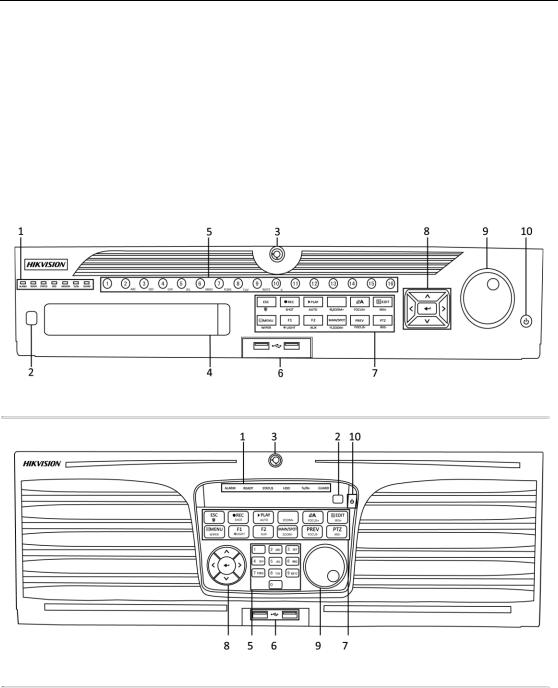
1.1.2 DS-8600NI and DS-7700NI Series |
||||||||||
Figure 1. 3 DS-8600NI-K8 Series
9
Network Video Recorder Quick Start Guide
Figure 1. 4 DS-7700NI Series
Table 1. 2 Panel Description
|
No. |
|
|
|
Name |
|
|
Function Description |
|
||
|
|
|
|
|
|
|
|||||
|
|
|
|
|
|
|
POWER |
|
|
Turns green when NVR is powered up. |
|
|
1 |
|
|
Status |
|
|
|
|
|
|
|
|
|
|
|
|
HDD |
|
|
Blinks red when HDD is reading/writing. |
|||
|
|
|
Indicators |
|
|
|
|
||||
|
|
|
|
|
|
|
|
|
|
|
|
|
|
|
|
|
|
|
Tx/Rx |
|
|
Blinks green when network connection is functioning normally. |
|
|
|
|
|
|
|
|
|
|
|
|
|
|
|
|
|
|
|
|
|
|
|
The Enter button is used to confirm selection in menu mode; or |
|
|
|
|
|
|
|
|
|
|
|
||
|
|
|
|
|
|
|
|
|
|
used to check checkbox fields and ON/OFF switch. |
|
|
|
|
|
|
|
|
|
|
|
In playback mode, it can be used to play or pause the video. |
|
|
|
|
|
|
|
|
|
|
|
|
|
|
2 |
|
|
|
ENTER |
|
|
In single-frame play mode, pressing the Enter button will play the |
|||
|
|
|
|
|
|
video by a single frame. |
|||||
|
|
|
|
|
|
|
|
|
|
||
|
|
|
|
|
|
|
|
|
|
In auto sequence view mode, the buttons can be used to pause or |
|
|
|
|
|
|
|
|
|
|
|
resume auto sequence. |
|
|
|
|
|
|
|
|
|
|
|
The Enter button is used to confirm selection in menu mode; or |
|
|
|
|
|
|
|
|
|
|
|
used to check checkbox fields and ON/OFF switch. |
|
|
|
|
|
|
|
|
|
|
|
In menu mode, the direction buttons are used to navigate between |
|
|
|
|
|
|
|
|
|
|
|
||
|
|
|
|
|
|
|
|
|
|
different fields and items and select setting parameters. |
|
|
|
|
|
|
|
|
|
|
|
In playback mode, the Up and Down buttons are used to speed up |
|
|
3 |
|
|
DIRECTION |
|
|
and slow down record playing, and the Left and Right buttons are |
||||
|
|
|
|
|
used to move the recording 30s forwards or backwards. |
||||||
|
|
|
|
|
|
|
|
|
|
||
|
|
|
|
|
|
|
|
|
|
In the image setting interface, the up and down button can adjust |
|
|
|
|
|
|
|
|
|
|
|
the level bar of the image parameters. |
|
|
|
|
|
|
|
|
|
|
|
In live view mode, these buttons can be used to switch channels. |
|
|
4 |
|
|
|
Back |
|
|
Back to the previous menu. |
|||
|
|
|
|
|
|
|
|
|
|
|
|
|
5 |
|
|
POWER ON/OFF |
|
|
Power on/off switch. |
||||
|
|
|
|
|
|
|
|
|
|
|
|
|
6 |
|
|
|
MENU |
|
|
Access the main menu interface. |
|||
|
|
|
|
|
|
|
|
|
|
|
|
|
7 |
|
|
USB Interface |
|
|
Universal Serial Bus (USB) ports for additional devices such as |
||||
|
|
|
|
|
USB mouse and USB Hard Disk Drive (HDD). |
||||||
|
|
|
|
|
|
|
|
|
|
||
10
 Loading...