

Hikvision DS-6701HFI-SATA, DS-6701HFI, DS-6704HFI-SATA, DS-6704HFI, DS-6708HFI-SATA User Manual
...
User Manual of DS-6700 Series Network Audio/Video Encoder
Network Audio/Video Encoder
User Manual (V1.1.0)
UD.6L0202D1098A01

User Manual of DS-6700 Series Audio/Video Encoder
Hikvision® Network Digital Video Server User’s Manual
This manual, as well as the software described in it, is furnished under license and may be used or copied only in
accordance with the terms of such license. The content of this manual is furnished for informational use only, is
subject to change without notice, and should not be construed as a commitment by Hikvision Digital Technology
Co., Ltd. (Hikvision). Hikvision assumes no responsibility or liability for any errors or inaccuracies that may
appear in the book.
Except as permitted by such license, no part of this publication may be reproduced, stored in a retrieval system, or
transmitted, in any form or by any means, electronic, mechanical, recording, or otherwise, without the prior
written permission of Hikvision.
HIKVISION MAKES NO WARRANTIES, EXPRESS OR IMPLIED, INCLUDING WITHOUT LIMITATION
THE IMPLIED WARRANTIES OF MERCHANTABILITY AND FITNESS FOR A PARTICULAR PURPOSE,
REGARDING THE HIKVISION SOFTWARE. HIKVISION DOES NOT WARRANT, GUARANTEE, OR
MAKE ANY REPRESENTATIONS REGARDING THE USE OR THE RESULTS OF THE USE OF THE
HIKVISION SOFTWARE IN TERMS OF ITS CORRECTNESS, ACCURACY, RELIABILITY,
CURRENTNESS, OR OTHERWISE. THE ENTIRE RISK AS TO THE RESULTS AND PERFORMANCE OF
THE HIKVISION SOFTWARE IS ASSUMED BY YOU. THE EXCLUSION OF IMPLIED WARRANTIES IS
NOT PERMITTED BY SOME STATES. THE ABOVE EXCLUSION MAY NOT APPLY TO YOU.
IN NO EVENT WILL HIKVISION, ITS DIRECTORS, OFFICERS, EMPLOYEES, OR AGENTS BE LIABLE
TO YOU FOR ANY CONSEQUENTIAL, INCIDENTAL, OR INDIRECT DAMAGES (INCLUDING
DAMAGES FOR LOSS OF BUSINESS PROFITS, BUSINESS INTERRUPTION, LOSS OF BUSINESS
INFORMATION, AND THE LIKE) ARISING OUT OF THE USE OR INABILITY TO USE THE HIKVISION
SOFTWARE EVEN IF HIKVISION HAS BEEN ADVISED OF THE POSSIBILITY OF SUCH DAMAGES.
BECAUSE SOME STATES DO NOT ALLOW THE EXCLUSION OR LIMITATION OF LIABILITY FOR
CONSEQUENTIAL OR INCIDENTAL DAMAGES, THE ABOVE LIMITATIONS MAY NOT APPLY TO
YOU.
1
User Manual of DS-6700 Series Audio/Video Encoder
Regulatory information
FCC information
FCC compliance: This equipment has been tested and found to comply with the limits for a digital device,
pursuant to part 15 of the FCC Rules. These limits are designed to provide reasonable protection against harmful
interference when the equipment is operated in a commercial environment. This equipment generates, uses,
and can radiate radio frequency energy and, if not installed and used in accordance with the instruction manual,
may cause harmful interference to radio communications. Operation of this equipment in a residential area is
likely to cause harmful interference in which case the user will be required to correct the interference at his own
expense.
FCC conditions
This device complies with part 15 of the FCC Rules. Operation is subject to the following two conditions:
1. This device may not cause harmful interference.
2. This device must accept any interference received, including interference that may cause undesired operation.
EU Conformity Statement
This product and - if applicable - the supplied accessories too are marked with "CE" and comply therefore with
the applicable harmonized European standards listed under the Low Voltage Directive 2006/95/EC, the EMC
Directive 2004/108/EC, the RoHS Directive 2011/65/EU.
2012/19/EU (WEEE directive): Products marked with this symbol cannot be disposed of as unsorted municipal
waste in the European Union. For proper recycling, return this product to your local supplier upon the purchase of
equivalent new equipment, or dispose of it at designated collection points. For more information see:
www.recyclethis.info.
2006/66/EC (battery directive): This product contains a battery that cannot be disposed of as unsorted municipal
waste in the European Union. See the product documentation for specific battery information. The battery is
marked with this symbol, which may include lettering to indicate cadmium (Cd), lead (Pb), or mercury (Hg). For
proper recycling, return the battery to your supplier or to a designated collection point. For more information see:
www.recyclethis.info.
2

User Manual of DS-6700 Series Audio/Video Encoder
Preventive and Cautionary Tips
Before connecting and operating your Encoder, please be advised of the following tips:
Ensure unit is installed in a well-ventilated, dust-free environment.
Keep all liquids away from the Encoder.
Please check the power supply to avoid the damage caused by voltage mismatch.
Please make sure the Encoder work in the allowed range of temperature and humidity.
Please keep the device horizontal and avoid the installation under severe vibration environment.
The dust board will cause a short circuit after damping; Please dedust regularly for the board, connector,
chassis fan with brush.
Improper use or replacement of the battery may result in hazard of explosion. Replace with the same or
equivalent type only. Dispose of used batteries according to the instructions provided by the battery
manufacturer.
3

User Manual of DS-6700 Series Audio/Video Encoder
TABLE OF CONTENTS
Chapter 1 Introduction ............................................................................................................. 7
1.1 Description ...................................................................................................................... 7
1.2 Models ............................................................................................................................ 7
1.3 Features .......................................................................................................................... 7
Chapter 2 Structure ................................................................................................................ 10
2.1 Front Panel .................................................................................................................... 10
2.2 Rear Panel ..................................................................................................................... 12
2.3 Alarm Connections ....................................................................................................... 15
2.3.1 Alarm Input Connections ....................................................................................... 15
2.3.2 Alarm Output Connections .................................................................................... 15
Chapter 3 Network Parameters Configuration ....................................................................... 17
3.1 Searching Active Devices Online ................................................................................... 17
3.2 Modifying Network Parameters .................................................................................... 18
Chapter 4 Access to DS-6700 by Client Software ................................................................... 20
4.1 Starting iVMS-4200 Client Software ............................................................................. 20
4.2 Accessing to DS-6700 .................................................................................................... 20
4.2.1 Adding Device ........................................................................................................ 21
4.2.2 Starting Live View .................................................................................................. 22
Chapter 5 Access to DS-6700 by WEB Browser ...................................................................... 24
5.1 Installing Web Components ......................................................................................... 24
5.2 Main Page ..................................................................................................................... 26
Chapter 6 Live View ................................................................................................................ 27
6.1 Starting Live View ......................................................................................................... 27
6.2 Capturing Picture .......................................................................................................... 28
6.3 Operating PTZ Control .................................................................................................. 28
6.3.1 Operating PTZ Movement ..................................................................................... 29
6.3.2 Setting / Calling a Preset ........................................................................................ 30
6.4 Configuring Video Parameters ...................................................................................... 31
4

User Manual of DS-6700 Series Audio/Video Encoder
Chapter 7 Device Configuration.............................................................................................. 33
7.1 Local Configuration ....................................................................................................... 33
7.2 Configuring Time Settings ............................................................................................. 34
7.3 Network Settings .......................................................................................................... 35
7.3.1 Configuring TCP/IP Settings ................................................................................... 35
7.3.2 Configuring Port Settings ....................................................................................... 36
7.3.3 Configuring DDNS Settings .................................................................................... 36
7.3.4 Configuring PPPoE Settings.................................................................................... 39
7.3.5 Configuring Email Settings ..................................................................................... 39
7.3.6 Adding Network Disk ............................................................................................. 41
7.3.7 Configuring SNMP Settings .................................................................................... 43
7.3.8 Configuring QoS Settings ....................................................................................... 44
7.3.9 Configuring FTP Settings ........................................................................................ 45
7.3.10 Configuring SOCKS Settings ................................................................................. 46
7.3.11 Configuring UPnP
TM
Settings ................................................................................ 47
7.3.12 Configuring HTTPS Settings .................................................................................. 48
7.3.13 Configuring Bonjour Settings ............................................................................... 49
7.3.14 Configuring IP Address Filter ............................................................................... 50
7.3.15 Configuring Multicast Address ............................................................................. 51
Chapter 8 Camera Settings ..................................................................................................... 52
8.1 Configuring OSD Settings .............................................................................................. 52
8.1.1 Configuring Display Settings .................................................................................. 52
8.1.2 Configuring Text Overlay ....................................................................................... 53
8.2 Configuring Video Settings ........................................................................................... 55
8.3 Configuring Snapshot Settings ...................................................................................... 56
8.4 Configuring and Handling Alarms ................................................................................. 57
8.4.1 Configuring Motion Detection ............................................................................... 57
8.4.2 Configuring External Alarm Input .......................................................................... 61
8.4.3 Configuring Video Loss Alarm ................................................................................ 63
8.4.4 Configuring Tamper-proof Alarm .......................................................................... 63
5

User Manual of DS-6700 Series Audio/Video Encoder
8.4.5 Handling Exception ................................................................................................ 64
8.5 Configuring Privacy Mask ............................................................................................. 65
8.6 Configuring RS-232/485 Settings .................................................................................. 66
8.6.1 RS-232 Settings ...................................................................................................... 66
8.6.2 RS-485 Settings ...................................................................................................... 66
Chapter 9 Record/Capture Settings ........................................................................................ 68
9.1 Configuring Holiday Settings......................................................................................... 68
9.2 Configuring Scheduled Record/Capture ....................................................................... 69
Chapter 10 Playback ............................................................................................................... 73
Chapter 11 Managing User Accounts ..................................................................................... 75
11.1 Adding a User .............................................................................................................. 75
11.2 Modifying a User......................................................................................................... 76
11.3 Deleting a User ........................................................................................................... 77
Chapter 12 Log Search and Maintenance ............................................................................... 78
12.1 Log Search ................................................................................................................... 78
12.2 Viewing Device Information ....................................................................................... 79
12.3 Maintenance ............................................................................................................... 79
12.3.1 Restarting the Device ........................................................................................... 80
12.3.2 Restoring Default Settings ................................................................................... 80
12.3.3 Importing/Exporting Configuration Files ............................................................. 81
12.3.4 Upgrading the System ......................................................................................... 81
Chapter 13 FAQ....................................................................................................................... 82
6

User Manual of DS-6700 Series Audio/Video Encoder
Chapter 1 Introduction
1.1 Description
Developed on the basis of the latest encoding technology, DS-6700 Series Audio/Video Encoder Server allows the
analog signal to be digitized and then stored in hard disk or transmitted via network, capable of encoding at up to
WD1(PAL: 960×576, NTSC: 960×480) or 4CIF resolution.
Adopting the latest embedded processor, DS-6700 Series Audio/Video Encoder provides more powerful
capabilities in audio/video encoding; data storage via SATA or network disk; various network protocols are
supported; and code downloaded in FLASH ensures high stability and reliability of system performance.
1.2 Models
According to the different resolution, connection to HDD and channel numbers, the DS-6700 Series Encoder
Server can be classified into the following models:
DS-6701HFI, DS-6704HFI, DS-6708HFI, DS-6716HFI
DS-6701HWI, DS-6704HWI, DS-6708HWI, DS-6716HWI
DS-6701HFI-SATA, DS-6704HFI-SATA, DS-6708HFI-SATA, DS-6716HFI-SATA
DS-6701HWI-SATA, DS-6704HWI-SATA, DS-6708HWI-SATA, DS-6716HWI-SATA
Description:
DS-6700HFI Series: 1/4/8/16 video inputs; support up to 4CIF resolution; 1 microSD card can be
connected to DS-6701/6704HFI for local recording.
DS-6700HFI-SATA Series: 1/4/8/16 video inputs; support up to 4CIF resolution; 1 SATA HDD can be
connected with up to 4TB capacity for local recording.
DS-6700HWI Series: 1/4/8/16 video inputs; support up to WD1 resolution, with 4CIF, 2CIF, CIF and QCIF
selectable; 1 microSD card can be connected to DS-6701/6704HWI for local recording.
DS-6700HWI-SATA Series: 1/4/8/16 video inputs; support up to WD1 resolution, with 4CIF, 2CIF, CIF
and QCIF selectable; 1 SATA HDD can be connected with up to 4TB capacity for local recording.
1.3 Features
Encoding
Support H.264/MPEG4/MPEG2/MJPEG encoding standards.
Support encoding video at up to 4CIF resolution for DS-6700HFI (-SATA) models and up to WD1
resolution for DS-6700HWI (-SATA) models.
Dual stream encoding.
Either compound streams encoding or video stream encoding selectable; audio and video synchronization
during compound streams encoding.
Network
7

User Manual of DS-6700 Series Audio/Video Encoder
One 10M/100Mbps adaptive Ethernet interface (PoE) for DS-6701/6704HFI/HWI models.
One 10M/100M/1000Mbps adaptive Ethernet interface for DS-6708/6716HFI/HWI and
DS-6701/6704/6708/6716HFI/HWI-SATA models.
Accessible by multiple web browsers: IE, FireFox, Chrome and Safari.
Remote web browser access by HTTPS ensures high security.
Netfilter builds internet firewalls based on packet filtering.
QoS protocol enhances the data transmission performance.
Support SNMPv1/v2c/v3 simple network management protocol.
mDNS-based Apple’s Bonjour protocol enables automatic discovery of devices.
Support email notifications, FTP upload and alarms upload by SOCKS v4/v5 proxy server.
Zero configuration networking (Zeroconfig) enables the device to automatically obtain the IPv4 link-local IP
addresses (range: 169.254.1.0~169.254.254.255).
Auto/Manual port mapping by UPnP™.
Support PSIA, ONVIF, HIKCGI and GENETEC protocols.
Support SADP software to automatically search and discover the online devices in local network area.
Automatically get IP address by DHCP protocol.
RTSP/RTP standard stream media protocol allows user to live view by unicast.
Multicast address for live view of multiple cameras through network.
Two-way audio and single-directional broadcasting.
Transmission via RS-232 and RS-485 transparent channel.
Note: DS-6701HFI/HWI model provides no RS-232 interface.
Access to Internet by PPPoE method, and support Peanut Hull, DynDNS, HiDDNS, etc.
Set time by NTP.
Connectable with network HDD in NAS, IPSAN mode.
Send email by SMTP protocol, and support attachment of captured JPEG image and SSL encryption.
Remote JPEG image capturing with user-defined image resolution and quality.
PTZ Control
Support Multiple PTZ Protocols
Different channels can be configured with protocol type, RS-485 address, baud rate, data bit, stop bit, even &
odd parity, stream control method, etc.; and remote configuration of presets, patrols and patterns.
Digital Zooming (with Speed Dome)
When connected with Hikvision speed dome, digital zooming can be realized by clicking on the image
through client software.
PTZ linkage
Relay input alarm can be responded with PTZ linkage actions, e.g., callup of predefined presets, patrols or
patterns.
Alarm
Relay Alarm Input
Either NO mode or NC mode can be set.
Four different alarm arming periods are configurable.
Capabilities of triggering corresponding alarm handling methods, relay alarm output, buzzer alarm, upload
to control center, PTZ linkage, presets/patrols/patterns callup, etc.
Relay Alarm Output
Relay alarm output can be connected with alarm devices for alarm handling within arming period.
8

User Manual of DS-6700 Series Audio/Video Encoder
Exceptions
Exception Alarm Handling
Exception alarms include network disconnect alarm, IP address conflict alarm, illegal access alarm, etc.;
multiple alarm handling methods are supported, relay alarm output, buzzer alarm, upload to center, etc.
Exception Reboot
Software watchdog capability: for inspecting important threads and system resources of device; in case of
exceptions detected, the device will be automatically rebooted.
Firmware watchdog: for inspecting the firmware of device; in case of exceptions in system task scheduling,
the device will be automatically rebooted.
Logs
The system logs can be classified into the operation logs, alarm logs, exception logs and information logs.
User may search and view all recorded system logs by date or type, as well as export the logs to the text
format over network.
Note: Hard disk/network disk/microSD card must be connected before log operation.
9
User Manual of DS-6700 Series Audio/Video Encoder
Item
Description
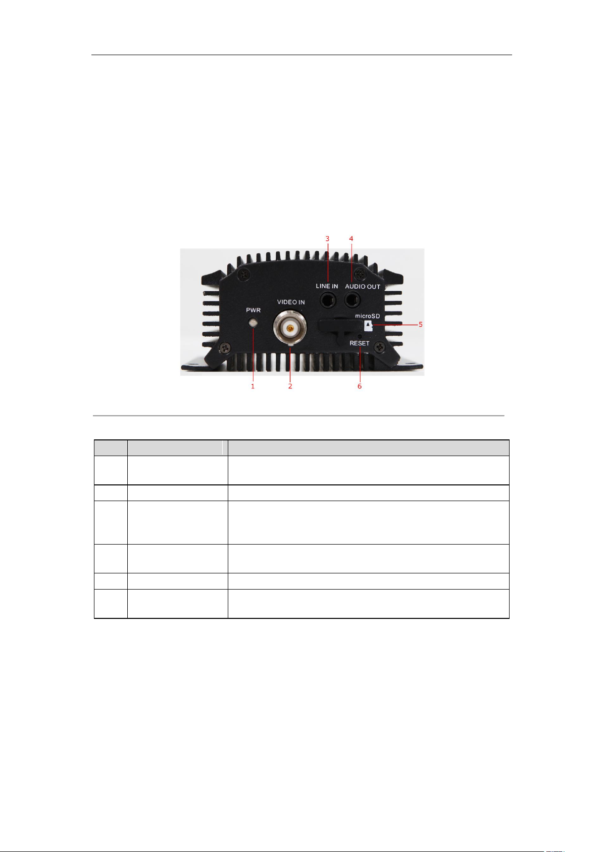
1
POWER LED
Indicator
Light in red when the device is powered on; light in orange
when the SD card is inserted.
2
VIDEO IN
BNC connector for video input.
3
LINE IN
3.5mm interface for two-way audio input or audio input;
connect to audio input device or active pick-up, microphone,
etc.
4
AUDIO OUT
3.5mm interface; connect to audio output device, e.g.,
loudspeaker, etc.
5
microSD
microSD interface for data storage.
6
Reset
Restore the factory default settings by holding the RESET
button for more than 15 seconds after power is turned on.
Chapter 2 Structure
2.1 Front Panel
DS-6701HWI/HFI:
Figure 2.1 Front Panel of DS-6701HWI/HFI
Table 2.1 Front Panel of DS-6701HWI/HFI
10
User Manual of DS-6700 Series Audio/Video Encoder
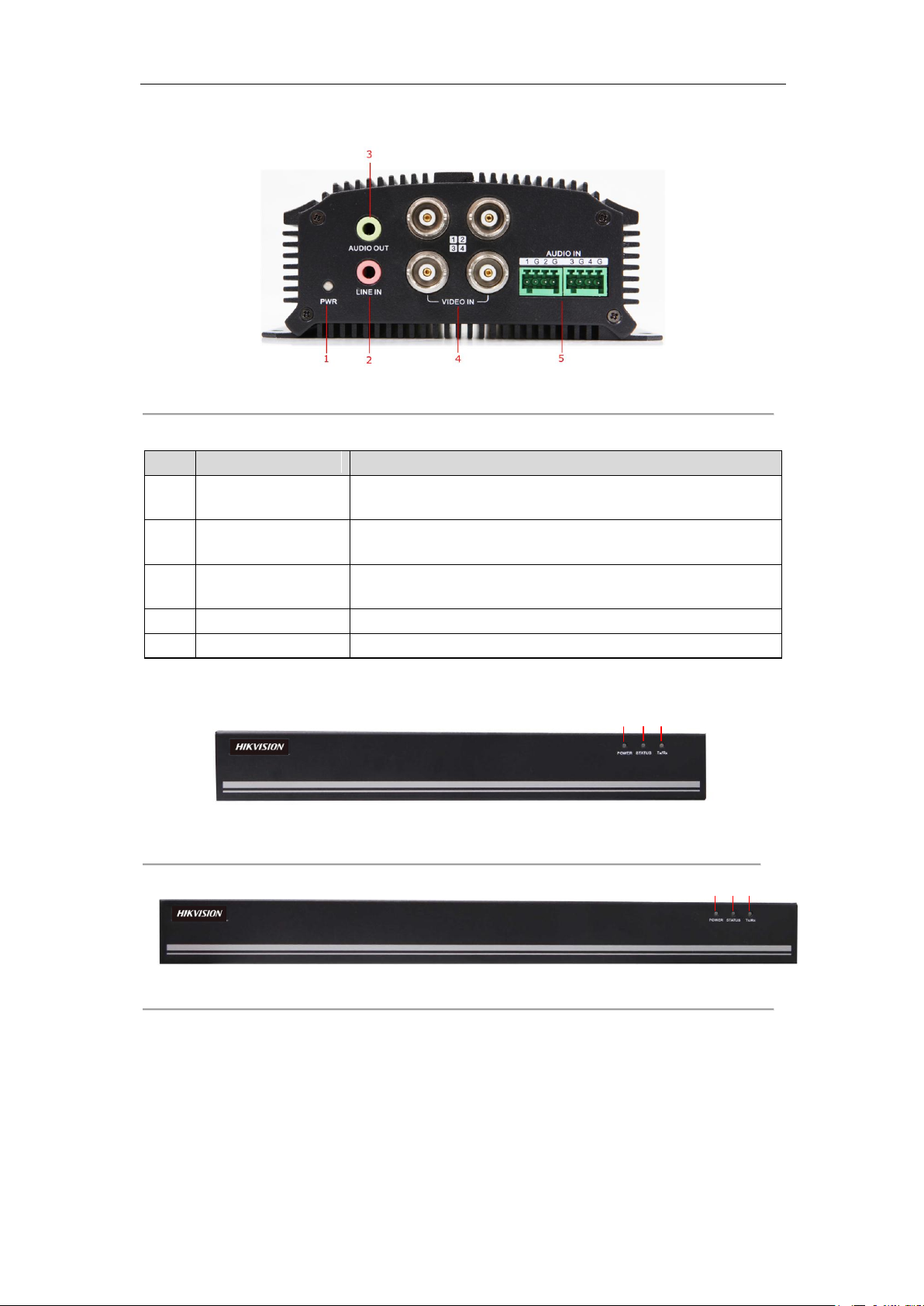
Item
Description
1
POWER LED
Indicator
Light in red when the device is powered on; light in orange
when the SD card is inserted.
2
LINE IN
3.5mm two-way audio input interface; connect to active
pick-up, microphone, etc.
3
AUDIO OUT
3.5mm interface; connect to audio output device, e.g.,
loudspeaker, etc.
4
VIDEO IN
BNC interface for video input.
5
AUDIO IN
Line input interface for audio input.
1
2
3
1 2 3
DS-6704HWI/HFI:
Figure 2.2 Front Panel of DS-6704HWI/HFI
Table 2.2 Front Panel of DS-6704HWI/HFI
DS-6708/6716 and DS-6701/6704/6708/6716-SATA:
Figure 2.3 Front Panel of DS-6708 and DS-6701/6704/6708-SATA
Figure 2.4 Front Panel of DS-6716 and DS-6716-SATA
11
User Manual of DS-6700 Series Audio/Video Encoder
Indicator
Description
1
POWER
Lights in red when the device is powered on.
2
STATUS
Lights in red when data is being read from or written to HDD.
Valid for DS-6708HWI/HFI-SATA model only.
3
Tx/Rx
1. Does not light when the network is not connected;
2. Blinks in green when the data is transmitting / receiving;
3. Blinks at higher frequency when the data for transmitting /
receiving is larger.
Item
Description
1
ALARM IN
/OUT
Relay alarm input/output.
Note: The alarm output terminal provides no JP2 pin.
2
RS-485
RS-485 serial interface; connect to pan/tilt unit, speed dome, etc.
3
LAN
10M/100Mbps adaptive Ethernet interface (PoE).
The right LED indicator lights in green when the network cable is
connected, and the left LED indicator blinks in orange when data
is transmitting / receiving.
4
DC12V
12V DC power supply.
5
GND
Grounding
Table 2.3 Front Panel of DS-6708/6716 and DS-6701/6704/6708/6716-SATA
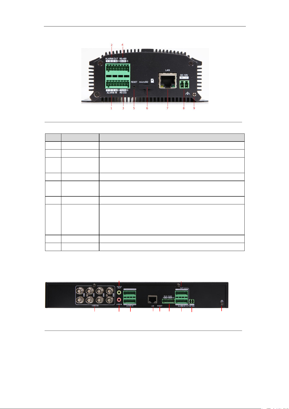
2.2 Rear Panel
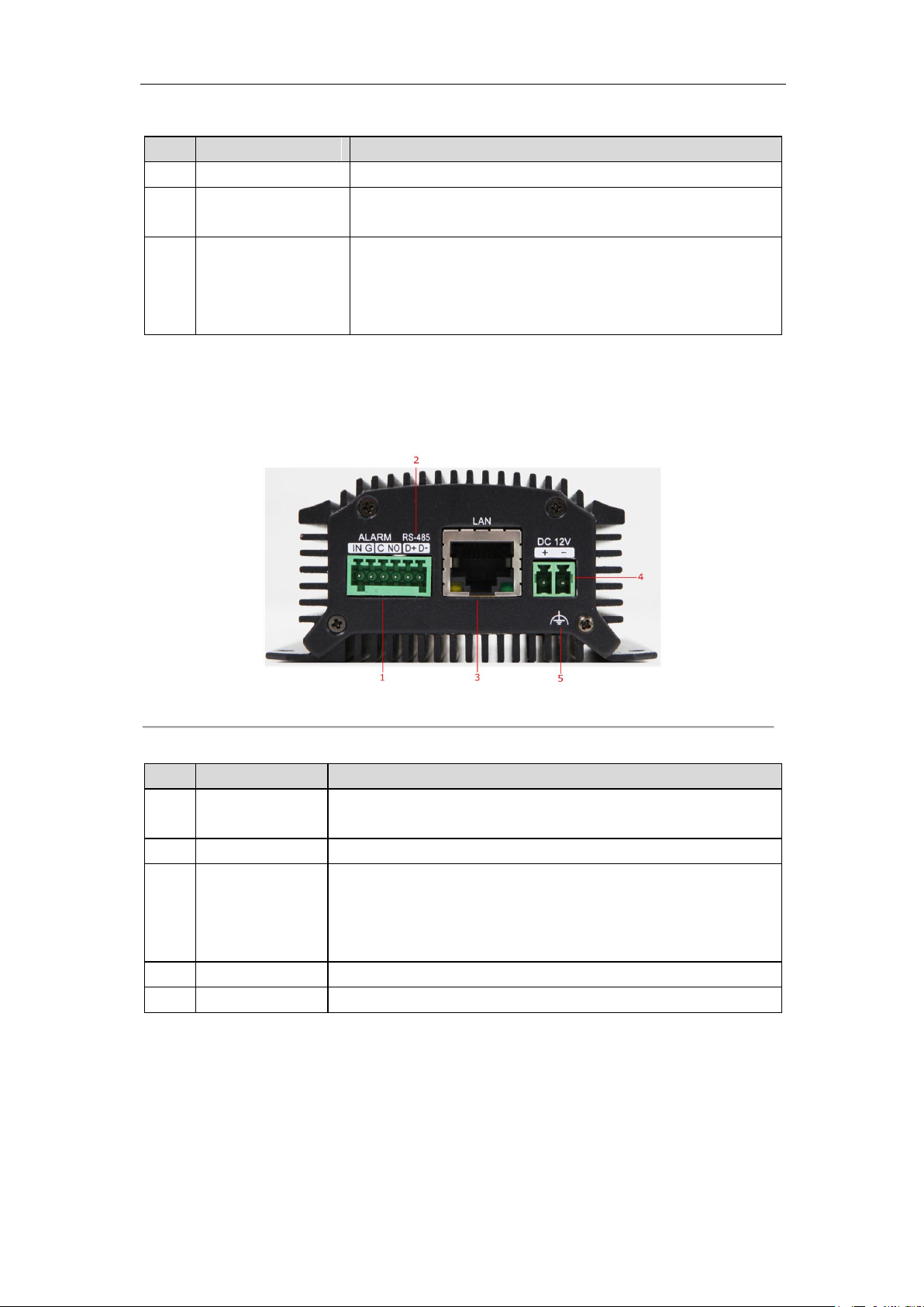
DS-6701HWI/HFI:
Figure 2.5 Rear Panel of DS-6701HWI/HFI
Table 2.4 Rear Panel of DS-6701HWI/HFI
12
User Manual of DS-6700 Series Audio/Video Encoder
Item
Description
1
ALARM IN
Relay alarm input.
2
ALARM OUT
Relay alarm output.
3
RS-232
Serial interface for configuration of device’s parameters or used as
transparent channel.
4
RS-485
RS-485 serial interface; connect to pan/tilt unit, speed dome, etc.
5
RESET
Restore the factory default settings by holding the RESET button for
more than 15 seconds after the device is turned on.
6
microSD
microSD interface for data storage.
7
LAN
10M/100Mbps adaptive Ethernet interface (PoE).
The right LED indicator lights in green when the network cable is
connected, and the left LED indicator blinks in orange when data is
transmitting / receiving.
8
DC12V
12V DC power supply.
9
GND
Grounding
214 5 6 7 8 10
9
3
11
DS-6704HWI/HFI:
Figure 2.6 Rear Panel of DS-6704HWI/HFI
Table 2.5 Rear Panel of DS-6704HWI/HFI
Note: The DS-6701HWI/HFI and DS-6704HWI/HFI models provide no beeper.
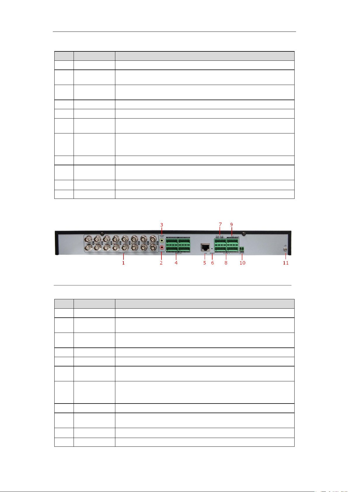
DS-6708HWI/HFI (-SATA):
Figure 2.7 Rear Panel of DS-6708HWI/HFI(-SATA)
Note: DS-6701/6704 HWI-SATA and DS-6701/6704 HFI-SATA models provide 1/4 video input and 1/4 audio
input interfaces on the rear panel.
13
User Manual of DS-6700 Series Audio/Video Encoder
Item
Description
1
VIDEO IN
BNC connectors for video input.
2
LINE IN
3.5mm two-way audio input interface; connect to active pick-up,
microphone, etc.
3
AUDIO OUT
3.5mm audio output interface; connect to audio output device, e.g.,
loudspeaker, etc.
4
AUDIO IN
Line input interface for audio input.
5
LAN
10M/100/1000Mbps adaptive Ethernet interface.
6
RESET
Restore the factory default settings by holding the RESET button for
more than 15 seconds after the device is turned on.
7
RS-232,
RS-485
RS-232 serial interface for configuration of device’s parameters or
used as transparent channel; RS-485 serial interface for connection to
pan/tilt unit, speed dome, etc.
8
ALARM IN
Relay alarm input.
9
ALARM
OUT
Relay alarm output.
10
DC12V
12V DC power supply.
11
GND
Grounding
Item
Description
1
VIDEO IN
BNC connectors for video input.
2
LINE IN
3.5mm two-way audio interface; connect to active pick-up,
microphone, etc.
3
AUDIO OUT
3.5mm audio output interface; connect to audio output device, e.g.,
loudspeaker, etc.
4
AUDIO IN
Line input interface for audio input.
5
LAN
10M/100/1000Mbps adaptive Ethernet interface.
6
RESET
Restore the factory default settings by holding the RESET button for
more than 15 seconds after power is turned on.
7
RS-232,
RS-485
RS-232 serial interface for configuration of device’s parameters or
used as transparent channel; RS-485 serial interface for connection to
pan/tilt unit, speed dome, etc.
8
ALARM IN
Relay alarm input.
9
ALARM
OUT
Relay alarm output.
10
DC12V
12V DC power supply.
11
GND
Grounding
Table 2.6 Rear Panel of DS-6708HWI/HFI (-SATA)
DS-6716HWI / HFI (-SATA):
Figure 2.8 Rear Panel of DS-6716HWI/HFI (-SATA)
Table 2.7 Rear Panel of DS-6716HWI/HFI (-SATA)
14
User Manual of DS-6700 Series Audio/Video Encoder
Encoder
Note: The relay input port of the Encoder should be set to NC mode.
Encoder
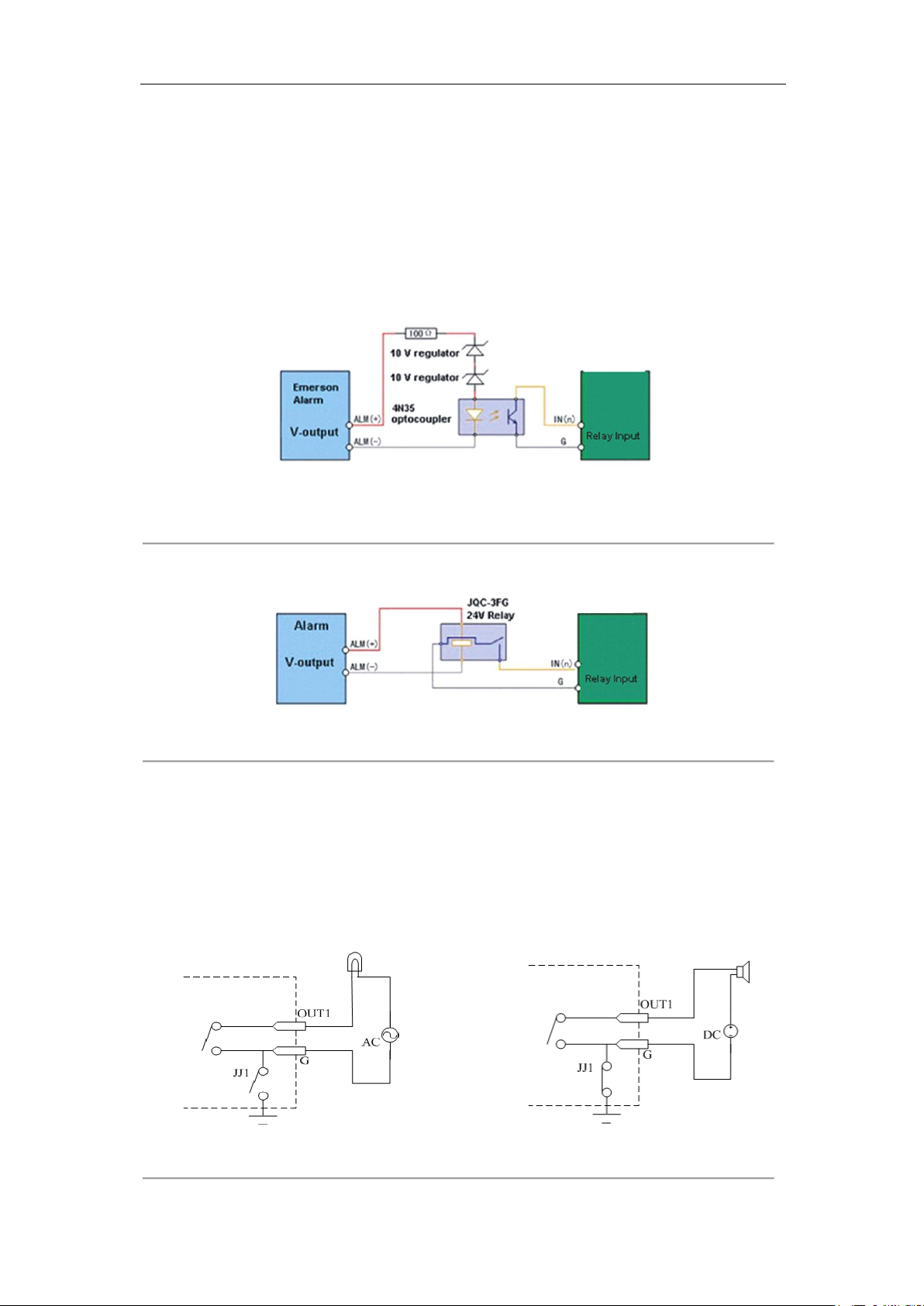
2.3 Alarm Connections
2.3.1 Alarm Input Connections
DS-6700 supports the open/close relay input as the alarm input mode. For the alarm input signal not in open/close
relay signal mode, please follow the connections shown as below:
Alarm input connections for Emerson Alarm:
Figure 2.9 Alarm Input Connections for Emerson Alarm
Alarm input connections for Normal Alarm:
Figure 2.10 Alarm Input Connections for Normal Alarm
2.3.2 Alarm Output Connections
DS-6700 supports the open/close relay input as the alarm output mode. The alarm input can be selected to NO or
NC. Different alarm output connection methods are applied to the AC or DC load. Please refer to the following
diagram:
Alarm output connections diagram:
Figure 2.11 Alarm Output Connections
15

User Manual of DS-6700 Series Audio/Video Encoder
Note: The DS-6701HWI/HFI has no JJ1 relay.
Please note the different connections of JJ1 shown above.
For DC load, JJ1can be safely used both in NC and NO methods, and it is recommended to use within the limit of
12V/1A. For external AC input, JJ1 must be open. The motherboard provides two jumpers, each corresponding to
one alarm output. And both of two jumpers are factory set to be connected.
16

User Manual of DS-6700 Series Audio/Video Encoder
Chapter 3 Network Parameters
Configuration
Purpose:
If you don’t know the IP address of the decoder and this is not the first time you use the decoder, you can use
SADP (IP finder) software or the Serial port tools to find out the IP address of the decoder and to configure the IP
address or other network parameters of it. It is recommended to change the default IP address for the first time to
use it.
This chapter aims to tell the procedures of using the SADP software to find and configure the IP address and other
parameters of the device.
Note:
For the first-time user, the default user name of DS-6700 is admin, and password is 12345. And the default IP
address is 192.0.0.64.
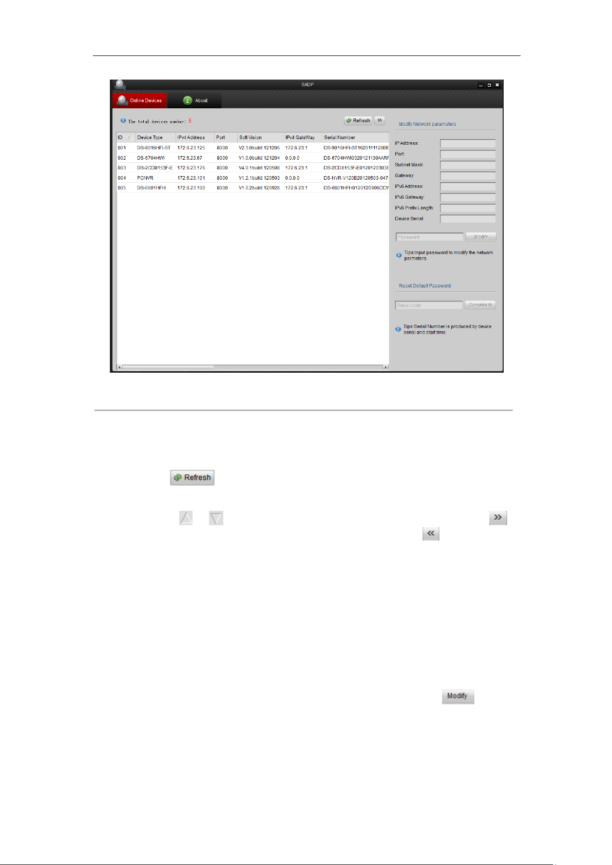
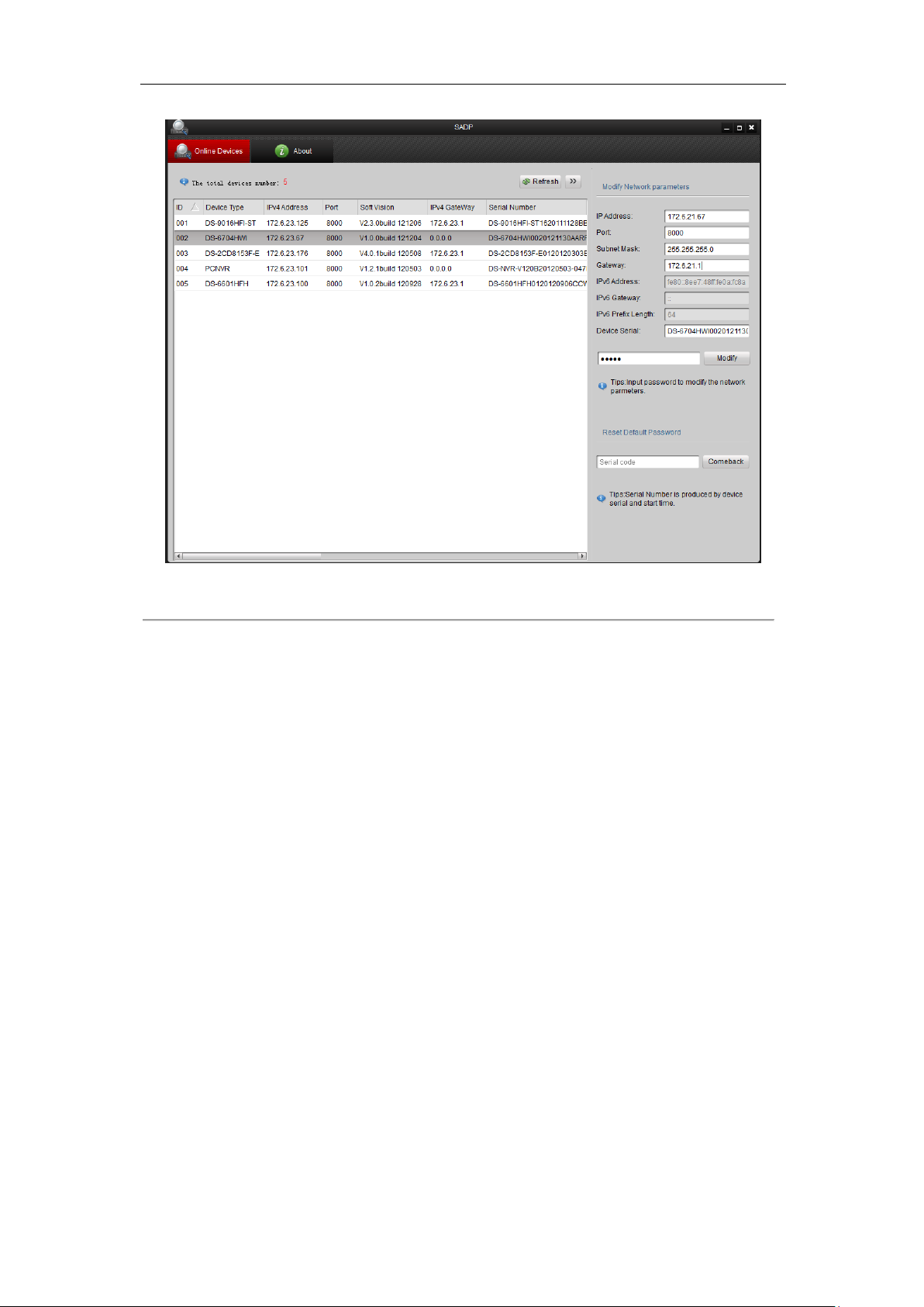
3.1 Searching Active Devices Online
Search online devices automatically
Click to run the SADP software and it will automatically search the online devices every 15
seconds from the subnet where your computer locates. It displays the total number and information of the
searched devices in the Online Devices interface. Device information including the device type, IP address, port
number, gateway, etc. will be displayed.
17
User Manual of DS-6700 Series Audio/Video Encoder
Figure 3.1 Search Online Device by SADP
Note: Device can be searched and displayed in the list in 15 seconds after it goes online; it will be removed from
the list in 45 seconds after it goes offline.
Search online devices manually
You can also click to refresh the online device list manually. The newly searched devices will be
added to the list.
Note: You can click or on each column heading to order the information; you can click to
expand the device table and hide the network parameter panel on the right side, or click to show the network
parameter panel.
3.2 Modifying Network Parameters
Steps:
1. Select the device to be modified in the device list and the network parameters of the device will be displayed
in the Modify Network Parameters panel on the right side.
2. Edit the modifiable network parameters, e.g., IP address, port number and gateway.
3. Enter the password of the admin account of the device in the Password field and click to save the
changes.
18
User Manual of DS-6700 Series Audio/Video Encoder
Figure 3.2 Modify Network Parameters
19
User Manual of DS-6700 Series Audio/Video Encoder
Chapter 4 Access to DS-6700 by Client Software
The DS-6700 Series Audio/Video Encoder can be accessed by iVMS-4200 client software (provided in attached
CD). Please refer to the User Manual of iVMS-4200 Client Software for more information.
The computer which runs the iVMS-4200 client software should meet the following requirements:
Operating System: Microsoft Windows 2000 or higher
CPU: Intel Pentium IV 3.0 GHz or higher
RAM: 1G or higher
Display: 1024×768 resolution or higher
4.1 Starting iVMS-4200 Client Software
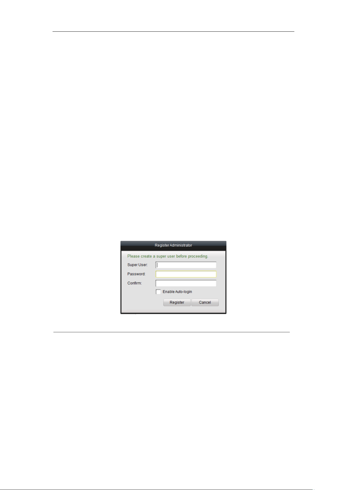
Install the iVMS-4200 software on your PC according to the prompts. For the first time to use the iVMS-4200
software, you need to register a super user for login.
Figure 4.1 Register User
Enter the super user name, password and confirm the password in the dialog box and click Register. Then, you
can log in as the super user.
Note: Enter, Space, and TAB keys are invalid for the user name and password. The password cannot be empty,
and it should not be less than six characters and can’t be copied and pasted.
4.2 Accessing to DS-6700
Click StartAll ProgramsiVMS-4200 Client to start the client software. After successful login, you can enter
the following main interface of the client software.
20
User Manual of DS-6700 Series Audio/Video Encoder
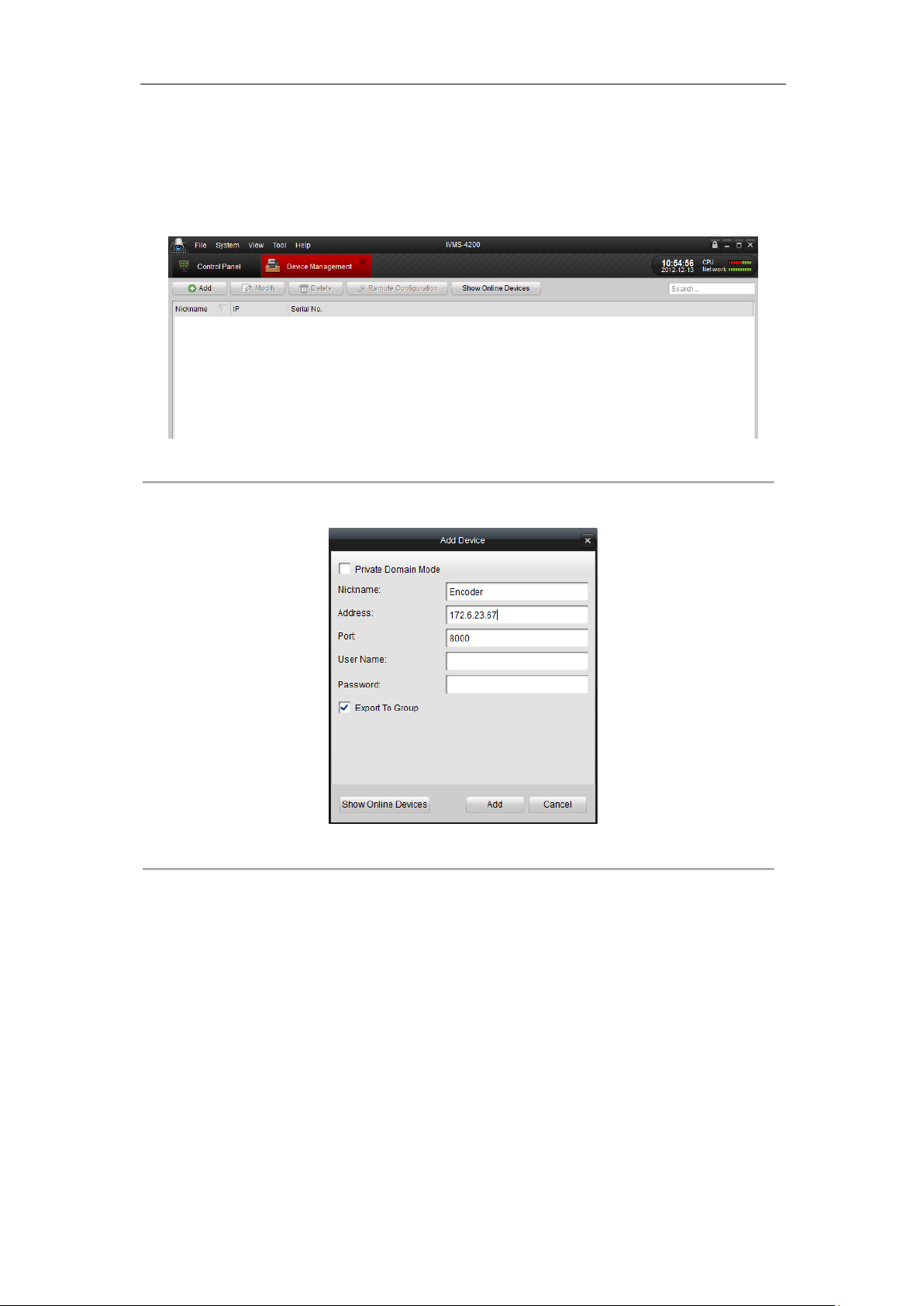
4.2.1 Adding Device
Steps:
1. Click Control Panel>Device Management to enter the Device Management page:
Figure 4.2 Device Management Page
2. Click the Add button to enter the Add Device dialog box:
Figure 4.3 Add Device
3. Edit a nickname for the device and then input the IP address, port number (default: 8000), login User Name
(default: admin) and Password (default: 12345) of the device.
Note: If you check the Private Domain Mode checkbox, you can add the device by IP server or HiDDNS.
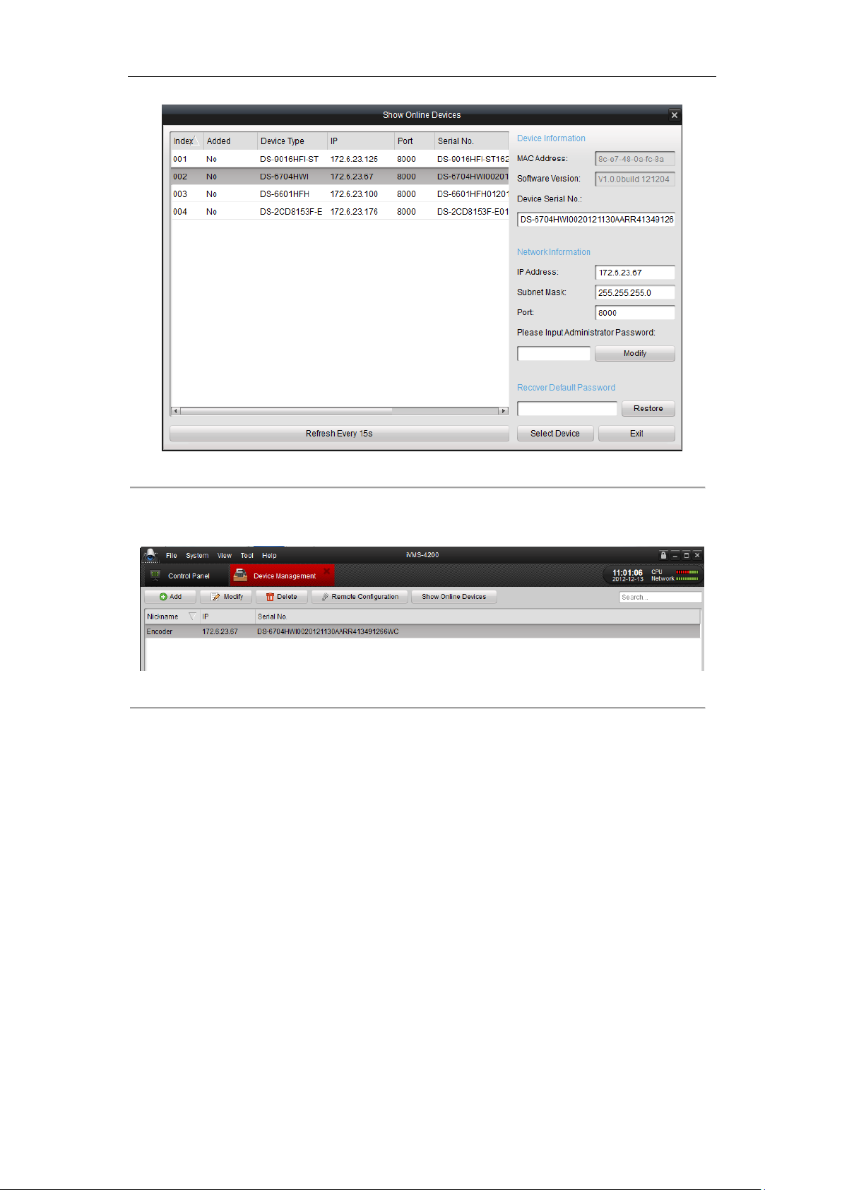
You can also click the Show online devices icon to search the online devices. All the online devices will show in
the list. Click to select the online device you want to add, and then click Select Device to enter the Add Device
dialog box. Enter the nickname and login user name and password.
21
User Manual of DS-6700 Series Audio/Video Encoder
Figure 4.4 Search Online Devices
4. Click Add to add the device.
5. The successfully added device (s) will be displayed on the device list.
Figure 4.5 List of Added Devices
4.2.2 Starting Live View
Click Control Panel > Main View to enter the Live View page:
22
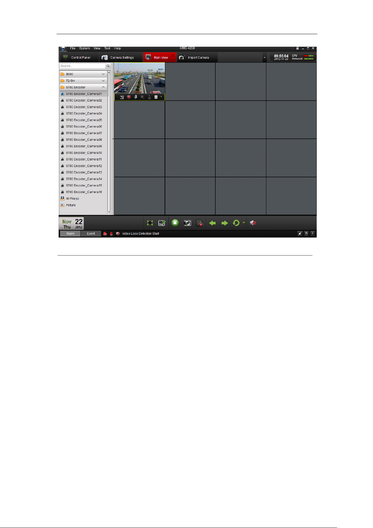
User Manual of DS-6700 Series Audio/Video Encoder
Figure 4.6 Start Live View
You can click the buttons on the toolbar to operate in the live view mode, e.g., capture picture, start/stop recording,
two-way audio, PTZ control (with PTZ camera connected to the encoder), digital zoom, open/close audio, play
back video files, etc.
Note: Please refer to the User Manual of iVMS-4200 Client Software for the detailed information.
23
User Manual of DS-6700 Series Audio/Video Encoder
Chapter 5 Access to DS-6700 by WEB
Browser
The DS-6700 can also be accessed by WEB Browser for configuration and operation. The supported WEB
browsers include: Internet Explorer 6/7/8/9, Firefox 3.5 and above, Chrome 8 and above, Safari 5.0.2 and above,
Windows XP SP1 and above (32-bit).
Before you start:
Before access, you need to configure the network settings of device according to Chapter 3.
Connect the device to the LAN, and prepare a PC connected to the same LAN with the device.
The factory default username of the device is admin and the password is 12345.
The factory default IP address of the device is 192.0.0.64.
5.1 Installing Web Components
Steps:
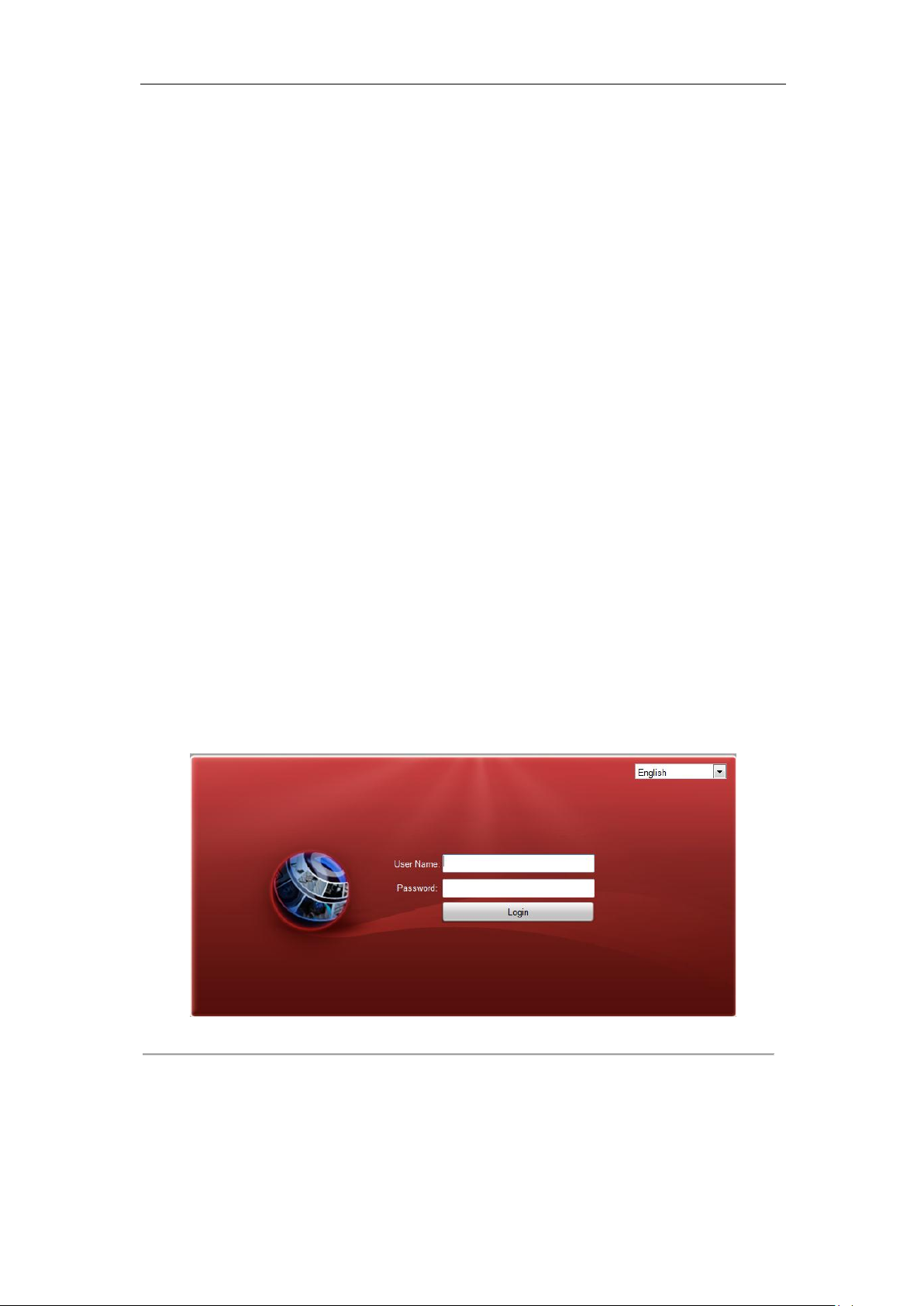
1. Open WEB browser, input the IP address of DS-6700 (e.g., http://192.0.0.64) and then press the Enter key
on PC. The system then will display the login interface.
Note: When the HTTPS feature is enabled, the system will use the HTTPS login mode (e.g.,
https://192.0.0.64) by default when you input the IP address. You can also input http://IP address/index.asp
(e.g., http://192.0.0.64/index.asp) if you want to use HTTP mode to log into the device.
Figure 5.1 Login Page
Input the user name (default: admin) and password (default: 12345) to log into the system.
2. On the main page of DS-6700, you need to download and install the plug-in.
(1) Click on the live view panel by following the hints on the screen.
24

User Manual of DS-6700 Series Audio/Video Encoder
Figure 5.2 Download and Install Plug-in
(2) Click Run or Save on the pop-up warning message box.
Figure 5.3 Run Web Components
(3) Click Next on the pop-up Setup dialog box.
Figure 5.4 Click Next
(4) When the installation completes, click Finish to finish the installation of Web Components.
25

User Manual of DS-6700 Series Audio/Video Encoder
Preset
Setting/Calling
PTZ Control
Device List
Window-division Live View Window Toolbar Video Parameters Settings
Menu Bar
Figure 5.5 Install the Web Components
5.2 Main Page
After successful login, you will enter the main page automatically.
Figure 5.6 Main Page
Description of the live view page:
Menu Bar: Enter the Live View, Playback, Log and Configuration page respectively.
Device List: Display the connected encoder and its channels.
Window-division: 1/4-division display mode.
Live Video Window: Display the live video of the current camera.
Toolbar: Realize functions in live view mode, e.g., live view, capture, recording, audio on/off, two-way audio, etc.
PTZ Control: Realize PTZ control of the camera (supports PTZ function), and the lighter and wiper control.
Preset Setting/Calling: Set and call the preset for the camera (supports PTZ function).
Video Parameters Settings: Configure the brightness, contrast, hue and saturation of the live video.
26

User Manual of DS-6700 Series Audio/Video Encoder
Icon
Description
Select the window-division mode.
/
Start/Stop live view
Capture pictures in live view mode
/
Manually start/stop recording
Enable e-PTZ
Previous page
Chapter 6 Live View
Live view shows you the video image getting from the connected camera in real time. After successful login, the
system will enter the live view page automatically.
6.1 Starting Live View
Steps:
1. In the live view window, select a playing window by clicking the mouse.
2. Double click a camera from the device list to start the live view.
Figure 6.1 Start Live View
3. You can click the button on the toolbar to start the live view of all cameras on the device list.
Refer to the following table for the description of buttons on the live view window:
Table 6.1 Description of Toolbar
27

User Manual of DS-6700 Series Audio/Video Encoder
Next page
/
Audio on/off
/
Start/Stop two-way audio
Note: Before using two-way audio function or recording with audio, please select the Stream Type to Video &
Audio on Section 8.2 Configuring Video Settings.
Full-screen Mode
You can double click on the live video to switch to the full-screen view mode. To switch back to the normal mode,
double click on the live video again.
Please refer to the following section for more information:
1. Capturing pictures on Section 6.2 Capturing Picture. .
2. Configuring recording on Chapter 9 Record/Capture Settings.
3. Setting the image quality of live view on Section 7.1 Local Configuration.
4. Setting the saving path for the recorded video files and captured pictures on Section 7.1 Local Configuration.
5. Setting the OSD text on live video on Section 8.1 Configuring OSD Settings.
6.2 Capturing Picture
In live view mode, click the button on the toolbar to capture the live pictures.
When the picture is captured, the following pop-up message box will appear at the lower right corner.
Figure 6.2 Picture Capture Succeeded
Notes:
1. The saving path for the captured pictures can be set at the Configuration > Local Configuration page.
2. The image is saved as a JPEG file on your computer.
6.3 Operating PTZ Control
Before you start:
1. Make sure the encoder is connected with the camera/dome which supports PTZ function. Connect the R+
2. The baud rate, PTZ control and address configured in the RS-485 Settings interface (Remote
and R- terminals of the pan/tilt unit or speed dome to RS-485 D+ and RS-485 D- terminals of the DS-6700
respectively.
Configuration > Serial Port Settings > 485 Serial Port), as shown in Figure 6.3, must be the same with the
parameters of the connected pan/tilt unit or speed dome.
28

User Manual of DS-6700 Series Audio/Video Encoder
Button
Description
Zoom in/out
Focus near/far
Iris open/close
Light
Wiper
Adjust speed of pan/tilt movement
Figure 6.3 RS-485 Settings
6.3.1 Operating PTZ Movement
In live view mode, you can use the PTZ control buttons to realize pan/tilt/zoom control of the camera lens.
There are 8 directional buttons (up, down, left, right, upper left, upper right, bottom left, bottom right) on the
display window when the mouse is located in the relative positions.
Click on the directional buttons to control the pan/tilt movement.
Figure 6.4 PTZ Control Panel
Click the zoom/iris/focus buttons to realize lens control.
Refer to the following table for description of PTZ control buttons:
Table 6.2 Description of PTZ Control Buttons
29

User Manual of DS-6700 Series Audio/Video Encoder
6.3.2 Setting / Calling a Preset
Setting a Preset:
1. In live view mode, select a preset number from the preset list.
Figure 6.5 Set a Preset
2. Use the PTZ control buttons to move the lens in the desired position. You can use any of the following
commands:
• Pan the camera to the right or left.
• Tilt the camera up or down.
• Zoom in or out.
• Refocus the lens.
3. Click the icon to finish the setting of current preset.
Note: Up to 256 presets are configurable depending on the PTZ protocol applied.
Calling a Preset:
This feature enables the camera to point to a specified preset scene when an event takes place.
For the pre-defined preset, you can call it at any time to the desired preset scene.
In live view mode, select a predefined preset from the list and click the icon to call a preset.
Figure 6.6 Call a Preset
Linking to Alarm:
30

User Manual of DS-6700 Series Audio/Video Encoder
The preset can also be used to link to the alarm input when there is alarm event occurring.
Figure 6.7 PTZ Linking
Please refer to Chapter 8.4 Configuring and Handling Alarms for the PTZ Linking settings (Remote
Configuration>Alarm Settings>Alarm Input>Linkage Method).
6.4 Configuring Video Parameters
Purpose:
You can configure the video parameters, including the brightness, contrast, saturation and hue.
Steps:
1. In the live view interface, click the button on the bottom right corner to spread the Video
Parameters Setting interface:
Figure 6.8 Video Parameters Settings
2. Select the mode according to different light conditions. Four modes are selectable:
Standard: in general lighting conditions (default).
Indoor: the image is relatively smoother.
Outdoor: the image is relatively clearer and sharper. The degree of contrast and saturation is high.
Dim Light: the image is smoother than the other three modes.
3. Move the slider to set the brightness, contrast, saturation and hue to 0~255. The default value is 128 for the
brightness, contrast and hue is 128 and 136 for the saturation.
31

User Manual of DS-6700 Series Audio/Video Encoder
4. Move the slider to set the sharpness to 0~15 and the denoising level to 0~3. The default value is 3 for the
sharpness and 1 for the denoising level.
Note: You can click the button to restore the default settings.
32

User Manual of DS-6700 Series Audio/Video Encoder
Chapter 7 Device Configuration
7.1 Local Configuration
Click Configuration > Local Configuration to enter the Local Configuration interface.
Figure 7.1 Local Configuration
Configure the following settings:
Protocol Type: Set the protocol type of stream transmission to TCP or UDP.
UDP: provides more real-time audio and video streams.
TCP: ensures complete deliver of streaming data and better video quality, yet its real-time effect is not so
good.
Stream Type: Select the stream type to main stream or sub stream used for live view by Web browser. Please
refer to Section 8.2 Configuring Video Settings for the parameters settings of the main stream and sub stream
respectively.
Image Size: Select the window-division view mode to 4:3, 16:9 or Auto-fill.
Record File Size: Select the size of packed video files during manual recording to 256M, 512M or 1G.
Live View Performance: Set the live viewing performance to Least Delay, Balanced (delay and fluency) or Best
Fluency.
Save record files to: Set the saving path for the manually recorded video files.
Save snapshots in live view to: Set the saving path for the manually captured pictures in live view mode.
Save snapshots when playback to: Set the saving path for the captured pictures in playback mode.
Save clips to: Set the saving path for the clipped video files in playback mode.
Save downloaded files to: Set the saving path for the downloaded video files or pictures.
Note: You can click the Browse button to change the directory for saving the video files and pictures.
33

User Manual of DS-6700 Series Audio/Video Encoder
7.2 Configuring Time Settings
Steps:
1. Click Remote Configuration > Device Parameters > Time Settings to enter the Time Settings interface:
Figure 7.2 Time Settings
2. Select the Time Zone.
Select the Time Zone that is closest to the device’s location from the drop-down menu.
Figure 7.3 Time Zone Settings
3. Configure the time synchronization by NTP server or by manually.
Configuring Time Sync by NTP Server
A Network Time Protocol (NTP) Server can be configured on your device to ensure the accuracy of system
date/time.
If the device is connected to a Dynamic Host Configuration Protocol (DHCP) network that has time server
properties configured, the camera will synchronize automatically with the time server.
Enable the NTP function by checking the checkbox, and configure the following settings:
NTP Server: IP address of NTP server.
NTP Port: Port of NTP server.
Interval: The time interval between the two synchronizing actions with NTP server. It can be set from 1 to
10080 minutes.
Figure 7.4 Time Sync by NTP Server
34

User Manual of DS-6700 Series Audio/Video Encoder
Note: If the device is connected to a public network, you should use a NTP server that has a time synchronization
function, such as the server at the National Time Center (IP Address: 210.72.145.44). If the device is set up in a
more customized network, NTP software can be used to establish a NTP server used for time synchronization.
Configuring Time Synchronization by Manually
Enable the Manual Time Sync function and then click the icon to set the system time from the pop-up
calendar. You can click the icon to quickly select the time.
Figure 7.5 Time Sync by Manually
You can also check the checkbox of Sync. with computer time to synchronize the time with the local PC.
4. Click the Save button to save the settings.
7.3 Network Settings
7.3.1 Configuring TCP/IP Settings
Network settings must be properly configured before you operate device over network.
Steps:
1. Click Remote Configuration > Network Settings > TCP/IP to enter the TCP/IP Settings interface:
Figure 7.6 TCP/IP Settings
35

User Manual of DS-6700 Series Audio/Video Encoder
2. Configure the NIC settings, including the NIC Type, IPv4 Address, IPv4 Subnet Mask, IPv4 Default
Gateway, and MTU settings.
Note: The valid value range of MTU is 500 ~ 1500.
3. If the DHCP server is available, you can click the checkbox of DHCP to automatically obtain an IP address
and other network settings from that server.
4. If the DNS server settings are required for some applications (e.g., sending email), you should properly
configure the Preferred DNS Server and Alternate DNS Sever here.
Figure 7.7 DNS Server Settings
5. Click the Save button to save the above settings.
7.3.2 Configuring Port Settings
Purpose:
You can set the port No. of the encoder, e.g., HTTP port, RTSP port and HTTPS port.
Steps:
1. Click Remote Configuration > Network Settings > Port to enter the Port Settings interface:
Figure 7.8 Port Settings
2. Set the HTTP port, RTSP port and HTTPS port of the camera.
HTTP Port: The default port number is 80.
RTSP Port: The default port number is 554.
HTTPS Port: The default port number is 443.
3. Click Save to save the settings.
Note: It will ask you to reboot the device to activate the settings.
7.3.3 Configuring DDNS Settings
If your device is set to use PPPoE as its default network connection, you may set Dynamic DNS (DDNS) to be
used for network access.
Prior registration with your DDNS Provider is required before configuring the system to use DDNS.
36

User Manual of DS-6700 Series Audio/Video Encoder
Steps:
1. Click the Remote Configuration > Network Settings > DDNS Settings to enter the DDNS Settings
interface:
Figure 7.9 DDNS Settings
2. Check the Enable DDNS checkbox to enable this feature.
3. Select DDNS Type. Four different DDNS types are selectable: IPServer, DynDNS, PeanutHull and
HiDDNS.
• DynDNS:
(1) Enter Server Address for DynDNS (e.g., members.dyndns.org).
(2) In the Device Domain Name text field, enter the domain obtained from the DynDNS website.
(3) Enter the User Name and Password registered in the DynDNS website.
(4) Click Save to save the settings.
Figure 7.10 DynDNS Settings
• IPServer:
(1) Enter Server Address for IPServer.
(2) Click Save to save the settings.
Note: For the IP Server, You have to apply a static IP, subnet mask, gateway and primary DNS from the ISP.
The Server IP should be entered with the static IP address of the PC that runs IPServer software.
37

User Manual of DS-6700 Series Audio/Video Encoder
Figure 7.11 IPServer Settings
• PeanutHull:
(1) Enter User Name and Password obtained from the PeanutHull website.
(2) Click Save to save the settings.
Figure 7.12 PeanutHull Settings
• HiDDNS:
(1) Enter the Server Address of the HiDDNS server: www.hik-online.com.
(2) Enter the Domain name of the device. You can register the alias of the device domain name in the
HiDDNS server first and then enter the alias to the domain name in the encoder; you can also enter
the domain name directly on the encoder to create a new one.
Note: If a new alias of the device domain name is defined in the encoder, it will replace the old one
registered on the server.
(3) Click Save to save the settings.
Figure 7.13 HiDDNS Settings
38

User Manual of DS-6700 Series Audio/Video Encoder
7.3.4 Configuring PPPoE Settings
Your device also allows access by Point-to-Point Protocol over Ethernet (PPPoE).
Steps:
1. Click the Remote Configuration > Network Settings > PPPoE Settings to enter the PPPoE settings
interface:
Figure 7.14 PPPoE Settings
2. Check the PPPoE checkbox to enable this feature.
3. Enter User Name, Password, and Confirm Password for PPPoE access.
Note: The User Name and Password should be assigned by your ISP.
4. Click the Save button to save and exit.
7.3.5 Configuring Email Settings
Purpose:
The device can be configured to send an Email notification to all designated receivers if an alarm event is detected,
e.g., motion detection event, video loss, tamper-proof, etc.
Before you start
1. Before configuring the Email settings, the device must be connected to a local area network (LAN) that
maintains an SMTP mail server. The network must also be connected to either an intranet or the Internet
depending on the location of the e-mail accounts to which you want to send notification.
2. Please configure the DNS Server settings under Remote Settings>Network Settings>TCP/IP before using
the Email function.
Steps:
1. Enter the Basic Network Settings (Remote Configuration > Network Settings > TCP/IP) to set the IPv4
Address, IPv4 Subnet Mask, IPv4 Default Gateway and the Preferred DNS Server.
2. Click the Remote Configuration > Network Settings > Email to enter the Email settings interface:
39

User Manual of DS-6700 Series Audio/Video Encoder
Figure 7.15 Email Settings (1)
3. Configure the following Email settings:
Authentication (optional): If your mail server requires authentication, check this checkbox to use
authentication to log in to this server and enter the login User Name and Password.
SMTP Server: The SMTP Server IP address or host name (e.g., smtp.263xmail.com).
SMTP Port: The SMTP port. The default TCP/IP port used for SMTP is 25.
Enable SSL: Click the checkbox to enable SSL if required by the SMTP server. When the SSL is
enabled, the default TCP/IP port used for SMTP is 465.
Interval: The interval refers to the time between two actions of sending attached pictures.
Attached Image: Check the checkbox of Attached Image if you want to send email with attached
alarm images.
Sender: The name of sender.
Sender’s Address: The Email address of sender.
Choose Receiver: Select the receiver to which the Email is sent. Up to 3 receivers can be configured.
Receiver: The name of user to be notified.
Receiver’s Address: The Email address of user to be notified.
40

User Manual of DS-6700 Series Audio/Video Encoder
Figure 7.16 Email Settings (2)
4. Click Save to save the Email settings.
Please refer to the following sections for more information:
Configure alarm linking methods with Send Email on Section 8.4.1 Configuring Motion Detection, Section 8.4.2
Configuring External Alarm Input, Section 8.4.3 Configuring Video Loss Alarm, Section 8.4.4 Configuring
Tamper-proof Alarm and Section 8.4.5 Handling Exception.
7.3.6 Adding Network Disk
For DS-6700HWI/HFI models, you must configure the network disk before operating the recording, playback or
log searching. For other models with SATA disks connected, the configuration of network disk is selectable.
Before you start:
1. The network storage device is available within the network and is properly connected.
2. The network storage device is configured with NAS or IP SAN mode (please refer to the User Manual of IP
SAN/NAS).
Steps:
1. Click Remote Configuration > Network Settings >NetHDD to enter the NetHDD settings interface.
41

User Manual of DS-6700 Series Audio/Video Encoder
Figure 7.17 Network Disk Settings
2. Enter the IP address of the Network Storage System and File Path in the text filed.
3. Select the type of Network Storage System to IP SAN or NAS.
NAS Mode: Enter the IP address of the storage device, and the default file path is /dvr/share, in which the
share name is user-defined during creating the DVR of the network storage.
IP SAN mode: Enter the IP address of the storage device, and the default file path is
iqn.2004-05.storos.t-service ID, in which the service ID is user-defined during creating the iSCSI volume of
the network storage.
4. Click the Save button to add the configured network disk.
5. Initialize the added network disk.
(1) Click Remote Configuration > HDD Management to enter the HDD settings menu, on which you can view
the capacity, free space, status, type and property of the added network disk.
(2) If the status of the network disk is Uninitialized, select the disk from the list by checking the checkbox and
click the Init button to start initializing the disk.
(3) When the initialization is complete, the status of disk will become Normal.
Figure 7.18 Initial Disk
6. Set the property of the added network disk.
Select the HDD No., and select the property from the drop-down menu to R/W, Read-only or Redundancy.
42

User Manual of DS-6700 Series Audio/Video Encoder
Figure 7.19 Set HDD Property
Notes:
1. Please refer to the User Manual of IP SAN/NAS for the creation of File Path in the network management.
2. Up to 8 NAS disks or IP SAN disk can be connected to the DS-6700.
7.3.7 Configuring SNMP Settings
Simple Network Management Protocol (SNMP) is an Internet-standard protocol for managing devices on IP
networks. You can use SNMP to get camera status, parameters and alarm related information.
Before you start:
Before setting the SNMP, please download the SNMP software and manage to receive the device information via
SNMP port. By setting the Trap Address, the device can send the alarm event and exception messages to the
surveillance center.
Note: The SNMP version you select should be the same as that of the SNMP software.
Steps:
1. Click Remote Configuration > Network Settings >SNMP to enter the SNMP settings interface.
2. Check the checkbox to enable SNMP v1 or SNMP v2c, and configure the read SNMP community (default:
public), write SNMP community (default: private), tap address (default: empty) and trap port (default: 162).
You can also enable both SNMP v1 and SNMP v2c.
Figure 7.20 SNMP Settings (1)
3. When the SNMPv3 is enabled, you can configure the read username (default: public).
Note: By default settings, the SNMPv1, SNMP v2c and SNMPv3 are disabled.
4. Select the security level to “no auth, no priv”, “auth, no priv”, “no auth, priv” or “auth, priv”.
43

User Manual of DS-6700 Series Audio/Video Encoder
Figure 7.21 SNMP Settings (2)
5. (1) When the security level is set to “auth, priv”, you can configure the Authentication Algorithm and
Private-key Algorithm parameters.
(2) When the security level is set to “no auth, no priv”, you cannot configure the Authentication Algorithm
and Private-key Algorithm parameters.
6. Set the SNMP port (default: 161).
7. Click Save to save the above settings.
7.3.8 Configuring QoS Settings
Purpose:
QoS (Quality of Service) can help solve the network delay and network congestion by configuring the priority of
data sending. The use of a QoS-aware network can prioritize traffic and thus allow critical flows to be served
before flows with lesser priority.
The encoder can mark the data packets for video/audio, event/alarm and management network traffics with
different DSCP values which identify different priority levels of data sending.
Steps:
1. Click Remote Configuration > Network Settings > QoS to enter the QoS settings interface:
44

User Manual of DS-6700 Series Audio/Video Encoder
Figure 7.22 QoS Settings
2. Check the checkbox to enable the QoS function.
3. Enter the DSCP (Differentiated Services Codepoint) value for the video/audio, event/alarm and management
traffic. This value is used to mark the traffic’s IP header. The DSCP value defines the priority level for the
specified type of traffic, for example, how much bandwidth to reserve for it.
The valid value range of the DSCP is 0-63. The higher DSCP value indicates higher priority level.
4. Click Save to save the settings.
Note: It will ask you to reboot the device to activate the settings.
7.3.9 Configuring FTP Settings
Purpose:
The captured pictures can be uploaded to FTP server.
Steps:
1. Click Remote Configuration > Network Settings > FTP to enter the FTP Settings interface:
Figure 7.23 FTP Settings
2. Check the checkbox of Enable FTP.
3. Configure the FTP settings, including server address, port, user name, password, directory and upload type.
Directory: In the Directory Structure field, you can select the root directory, parent directory and child
45

User Manual of DS-6700 Series Audio/Video Encoder
directory. When the parent directory is selected, you have the option to use the Device Name, Device
Number or Device IP for the name of the directory; and when the Child Directory is selected, you can use
the Camera Name or Camera No. as the name of the directory.
Upload type: To enable uploading the captured picture to the FTP server.
4. Click Save to save the settings.
Note: If you want to upload the captured pictures to FTP server, you have to enable the event-triggered
snapshot on Snapshot page. For detailed information, please refer to Section 8.3.
7.3.10 Configuring SOCKS Settings
Purpose:
SOCKet Secure (SOCKS) is an Internet protocol that routes network packets between a client and server through
a proxy server. This feature is useful if the encoder is located on a local network behind a firewall, and Email
notifications, FTP uploads, alarms, and such need to be sent to a destination outside the local network (such as the
Internet). The SOCKS4 and SOCKS5 are supported, of which the SOCKS5 additionally provides authentication
so only authorized users may access a server.
Steps:
1. Click Remote Configuration > Network Settings > SOCKS to enter the SOCKS Settings interface:
Figure 7.24 SOCKS Settings
2. Configure the following settings:
Server: Enter the address of the SOCKS server.
Server Port: Enter the port of the SOCKS server (default: 1080).
Server Type: Select the server type to SOCKS4 or SOCKS5. When you select SOCKS5, you can enable the
user authentication on the server and then enter the login user name and password here.
Local networks: Define the local network segment which does not need to use SOCKS proxy server. You
can enter multiple network addresses and use the semicolon (;) to separate them, e.g., 10.0.0.0/255.0.0.0;
172.16.0.0/255.240.0.0.
3. Click Save to save the settings.
46

User Manual of DS-6700 Series Audio/Video Encoder
7.3.11 Configuring UPnP
Purpose:
UPnP™ can permit the device seamlessly discover the presence of other network devices on the network and
establish functional network services for data sharing, communications, etc. If you want to use the UPnP™
function to enable the fast connection of the device to the WAN via a router, you should configure the UPnP™
parameters of the device.
Before you start:
If you want to enable the UPnP™ function of the device, you must enable the UPnP™ function of the router to
which your device is connected. When the network working mode of the device is set as multi-address, the
Default Route of the device should be in the same network segment as that of the LAN IP address of the router.
Steps:
1. Click Remote Configuration > Network Settings > NAT to enter the NAT settings interface.
2. Check the checkbox to enable the UPnPTM function.
3. Select the Port Mapping Mode to Auto or Manual.
When you select Auto, the mapping ports can be automatically assigned by the router.
When you select Manual, you should continue Step4 to edit the mapping ports.
TM
Settings
Figure 7.25 UPnPTM Settings-Auto
4. Configure the HTTP Port (for access by WEB browser), SDK Port Mapping (for access by client software),
RTSP Port and HTTPS Port respectively.
Notes:
1) You can use the default port No., or change it according to actual requirements.
2) The Ports indicate the port No. for mapping in the router.
5. Click Save to save the settings.
After port mapping is successful, you can view the status of the port mapping on the Port Status area.
47

User Manual of DS-6700 Series Audio/Video Encoder
Figure 7.26 UPnPTM Settings-Manual
7.3.12 Configuring HTTPS Settings
Purpose:
HTTPS (Hyper Text Transfer Protocol Secure) ensures the data transferred is encrypted using Secure Socket
Layer (SSL) or Transport Layer Security (TLS). HTTPS provides authentication of the web site and associated
web server that one is communicating with and create a secure channel over an insecure network.
HTTPS URLs begin with "https://" and use port 443 by default.
Steps:
1. Click Remote Configuration > Network Settings > HTTPS to enter the HTTPS settings interface.
2. Create the self-signed certificate or authorized certificate.
48

User Manual of DS-6700 Series Audio/Video Encoder
Figure 7.27 HTTPS Settings
Task1: Create the self-signed certificate
(1) Click the Create button to create the following dialog box.
Figure 7.28 Create Self-signed Certificate
(2) Enter the country, host name/IP, validity and other information.
(3) Click OK to save the settings.
Task2: Create the authorized certificate
(1) Click the Create button to create the certificate request.
(2) Download the certificate request and submit it to the trusted certificate authority for signature.
(3) After receiving the signed valid certificate, import the certificate to the device.
3. When you have successfully created and installed the certificate, check the checkbox to enable the HTTPS
function.
Note:
After the HTTPS feature is enabled, the system will use the HTTPS login mode by default when you input the IP
address (e.g., https://192.0.0.64). You can also input http://IP address/index.asp (e.g., http://192.0.0.64/index.asp)
if you want to use HTTP mode to log into the device.
7.3.13 Configuring Bonjour Settings
Purpose:
Bonjour is enabled by default, and the video encoder can be automatically detected by operating systems and
clients that support this protocol.
Before you start:
Make sure you have installed the Bonjour plug-in on your PC before enabling the Bonjour function.
Steps:
1. Click Remote Configuration > Network Settings > Bonjour to enter the Bonjour settings interface.
49

User Manual of DS-6700 Series Audio/Video Encoder
Figure 7.29 Bonjour Settings
2. Check the checkbox to enable the Bonjour function.
3. Edit the name of device. The name is shown when the device is detected by the system.
Note: Only the letters, numbers and “-” can be contained in the name.
4. Click Save to save the settings.
7.3.14 Configuring IP Address Filter
Purpose:
You can allow or forbid access by specified IP addresses to the encoder by enabling IP Address Filter.
Up to 256 IP address can be added to the list (allowed/forbidden) by Web Browser.
Steps:
1. Click Remote Configuration > Network Settings > IP Address Filter to enter the IP address filter settings
interface.
Figure 7.30 IP Address Filter Settings
2. Check the checkbox of Enable IP Address Filter.
3. Select the filter type of IP address to Allowed or Forbidden.
4. Click the Add button to add the IP address to be allowed or forbidden.
Figure 7.31 Add IP Address
5. Click the Add button to add the IP address to be allowed or forbidden.
Note: Up to 256 IP address can be added to the list (allowed/forbidden) by Web Browser.
6. Click Save to save the settings.
50

User Manual of DS-6700 Series Audio/Video Encoder
7.3.15 Configuring Multicast Address
Purpose:
The multicast address can be configured to realize live view for more than the maximum number of cameras
through network.
A multicast address spans the Class-D IP range of 224.0.0.0 to 239.255.255.255. It is recommended to use the IP
address ranging from 239.252.0.0 to 239.255.255.255.
Steps:
1. Click Remote Configuration > Network Settings > Advanced to enter the multicast address settings
interface.
Figure 7.32 Multicast Address Settings
2. Enter the multicast address in the text filed.
3. Click Save to save the settings.
51

User Manual of DS-6700 Series Audio/Video Encoder
Camera 01
Chapter 8 Camera Settings
8.1 Configuring OSD Settings
8.1.1 Configuring Display Settings
Purpose:
You can customize the camera name and time on the screen.
Steps:
1. Click the Remote Configuration >Camera Settings > Display Settings to enter the Display Settings
interface:
Figure 8.1 Display Settings
2. Select the camera from the drop-down list.
3. Edit the camera name in the text field of Camera Name.
Figure 8.2 Edit Camera Name
4. Select the display of camera name, date or week by checking the checkboxes if required.
5. Set the time format, date format and OSD display mode by selecting option from the drop-down list.
6. On the preview image, you can adjust the OSD location on the screen by moving the text frame.
52

User Manual of DS-6700 Series Audio/Video Encoder
Camera 01
12-11-2012 Tuesday 11:21:00
Figure 8.3 Adjust OSD Location
7. If you want to copy the display settings of the current camera to other cameras, spread the Copy to Camera
panel and select the camera(s) to copy, or click Select All to select all cameras.
Figure 8.4 Copy to Camera
8. Click Save to validate the above settings.
8.1.2 Configuring Text Overlay
Steps:
1. Click the Remote Configuration >Camera Settings > Text Overlay Settings to enter the Text Overlay
Settings interface.
2. Select the camera from the drop-down list.
3. Edit the user-defined text content.
Click the checkbox in the text box below and then input the characters. Up to 8 character strings can be
edited.
4. Click Save, and the edited text is shown on the image.
5. On the preview image, you can adjust the Text location on the screen by moving the text frame.
53

User Manual of DS-6700 Series Audio/Video Encoder
Highway A
Figure 8.5 Text Overlay Settings
6. If you want to copy the text overlay settings of the current camera to other cameras, spread the Copy to
Camera panel and select the camera(s) to copy, or click Select All to select all cameras.
Figure 8.6 Text Overlay Settings
7. Click Save to activate the above settings.
54

User Manual of DS-6700 Series Audio/Video Encoder
8.2 Configuring Video Settings
Steps:
1. Click Remote Configuration > Camera Settings >Video Settings to enter the Video Settings interface:
Figure 8.7 Video Settings
2. Select the camera from the drop-down list to configure.
3. Select the Stream Type of the camera to Main Stream (Normal), Main Stream (Event) or Sub Stream.
The main stream is usually for recording and live viewing with good bandwidth, and the sub stream can be
used for live viewing when the bandwidth is low. Refer to the Chapter 7.1 Local Configuration on changing
the main stream to sub stream for live viewing.
4. You can customize the following parameters for the selected Main Stream or Sub Stream:
Video Type: Select the video type to video stream, or video & audio composite stream. The audio signal
will be recorded only when the Video Type is Video & Audio.
Resolution: Select the resolution of the video input.
Bitrate Type: Select the bitrate type to constant or variable.
Video Quality: When bitrate type is selected to Variable, 6 levels of video quality can be configured.
Frame Rate: Set the frame rate to 1~30 fps.
The frame rate used to describe the frequency at which a video stream is updated is measured in frames per
second (fps). A higher frame rate is advantageous when there is movement in the video stream, as it
maintains image quality throughout.
Max. Bitrate: Set the Max. bitrate to 32~8192 Kbps.
I Frame Interval: Set the I frame interval to 1~ 400 (frames). The higher value results in lower video
quality.
Video Encoding: Select the video encoding standard to H.264, MPEG2, MPEG4 or MJPEG.
Note: When the MJPEG video encoding standard is selected, the frame rate can be set to 1~15fps and the
max. bitrate is not configurable.
5. If you want to copy the display settings of the current camera to other cameras, spread the Copy to Camera
55

User Manual of DS-6700 Series Audio/Video Encoder
panel and select the camera(s) to copy, or click Select All to select all cameras.
Figure 8.8 Copy to Camera
6. Click Save to save the above settings.
8.3 Configuring Snapshot Settings
Purpose:
You can configure the scheduled snapshot and event-triggered snapshot. The captured picture can be stored in the
HDD, SD card (if supported) or the netHDD. You can also upload the event-triggered snapshots to a FTP server.
Steps:
1. Click Remote Configuration > Camera Settings > Snapshot to enter the Snapshot settings interface:
Figure 8.9 Snapshot Settings
2. Select the channel No. from which the pictures to be captured.
3. Configure the timing snapshot and the event-triggered snapshot parameters, including the format, resolution,
quality and the interval between two snapshots.
4. Select the channel (s) you want to copy the same settings if needed.
5. Click Save to save the settings.
Notes:
1. The timing snapshots are stored in HDD, SD card (if supported) or netHDD. The event-triggered
snapshots can be uploaded to FTP.
2. You should check the checkbox in Motion Detection Settings or Alarm Input
56

User Manual of DS-6700 Series Audio/Video Encoder
interface. Please refer to Step 3 in Section 8.4.1 Configuring Motion Detection or Step 4 in Section
8.4.2 Configuring External Alarm Input.
3. Please refer to Section 7.3.9 Configuring FTP Settings for more details to configure FTP parameters.
8.4 Configuring and Handling Alarms
Purpose:
This section explains how to configure the network camera to respond to alarm events, including Motion
Detection, External Alarm Input, Video Loss, Tamper-proof and Exception. And the alarm events can trigger the
alarm actions, such as Notify Surveillance Center, Send Email and Trigger Alarm Output.
8.4.1 Configuring Motion Detection
Motion detection is a feature which can alert the personnel and record the video for the motion occurred in the
surveillance scene.
Steps:
1. Set the Motion Detection Area
Steps:
(1) Click Remote Configuration> Camera Settings> Motion Detection to enter the motion detection
settings interface.
(2) Select the camera to configure the motion detection.
(3) Check the checkbox of Enable Motion Detection.
Figure 8.10 Motion Detection Settings
(4) Click the button. Draw motion detection area by clicking and dragging the mouse in
57

User Manual of DS-6700 Series Audio/Video Encoder
the live video image.
Note: You are allowed to draw 8 motion detection areas in the same image.
(5) Click the button to finish drawing.
You can click the button to clear all areas.
(6) Move the slide bar to set the sensitivity of the camera.
Figure 8.11 Motion Detection-Area Settings
(7) Click Save button to save the settings.
2. Set the Arming Schedule for Motion Detection
Steps:
(1) Click the Arming Time tab.
Figure 8.12 Motion Detection-Arming Time Settings
(2) Click the Edit button to edit the arming schedule.
58

User Manual of DS-6700 Series Audio/Video Encoder
Figure 8.13 Motion Detection-Edit Arming Schedule
Notes:
1. The time of each segment can’t be overlapped. Up to 8 segments can be configured for each day.
2. The Holiday option is available in the Schedule dropdown list when you have enabled holiday
schedule in Holiday settings.
(3) Choose the day you want to set the arming schedule.
(4) Click the button to set the time period for the arming schedule.
(5) After you set the arming schedule, you can copy the schedule to other days.(Optional)
(6) Click OK button to save the settings.
3. Set the Alarm Actions Taken for Motion Detection
Purpose:
You can specify the alarm type when an event is triggered.
Figure 8.14 Motion Detection-Linking Method
Steps:
59

User Manual of DS-6700 Series Audio/Video Encoder
(1) Click the Linkage Method tab to enter the setting interface.
(2) Select the alarming linkage method(s) including Audible Warning, Notify Surveillance Center, Send
Email and Upload to FTP.
Audible Warning
Trigger an audible beep when an alarm is detected.
Note: The DS-6701/6704HWI and DS-6701/6704HFI models provide no audio beep.
Notify Surveillance Center
Send an exception or alarm signal to remote alarm host when an event occurs. The alarm host refers to
the PC installed with Remote Client.
Send Email
Send an email with alarm information to a user or users when an event occurs.
Note: To send the Email when an event occurs, you need to go to the network setting interface to set
the related parameters. Refer to Section7.3.5 Configuring Email Settings.
Upload to FTP
Capture the image when an alarm is triggered and upload the picture to a FTP server.
(3) Select the channel you want to trigger an external alarm output when a motion detection event occurs.
Figure 8.15 Motion Detection-Trigger Alarm Output
Note: To trigger an external alarm output when an event occurs, you need to go to the Alarm Output
Settings interface to set the related parameters.
1) Click Remote Configuration> Alarm Settings> Alarm Output to enter the Alarm Output
Settings interface.
Figure 8.16 Motion Detection-Alarm Output Settings
2) Select one alarm output channel in the Alarm Output drop-down list.
3) The Delay time can be set to 5sec, 10sec, 30sec, 1min, 2min, 5min, 10min or Manual. The
60

User Manual of DS-6700 Series Audio/Video Encoder
Delay refers to the time duration that the alarm output remains in effect after alarm occurs.
Note: If you choose Manual, you need to manually disable the alarm output.
4) Click Edit to enter the Edit Schedule Time interface. The time schedule configuration is the
same as the Setting of the Arming Schedule for Motion Detection. Refer to Step 2 Set the Arming
Schedule for Motion Detection in Section 8.4.1 Configuring Motion Detection.
Figure 8.17 Motion Detection-Alarm Output Settings
5) Return to the Alarm Output Settings interface and click Save to save the settings.
(4) Select the channel you want to trigger recording when a motion detection event occurs.
Figure 8.18 Motion Detection-Alarm Linked Recording
(5) Click Save to save the settings of linking method motion detection.
8.4.2 Configuring External Alarm Input
Steps:
1. Click Remote Configuration> Alarm Settings> Alarm Input to enter the Alarm Settings interface.
2. Choose the alarm input number and the Alarm Type. The alarm type can be NO (Normally Open) and NC
(Normally Closed).
61

User Manual of DS-6700 Series Audio/Video Encoder
Figure 8.19 Alarm Input Settings-Arming Time
3. Set the arming schedule for the alarm input. Refer to Step 2 Set the Arming Schedule for Motion Detection
in Section 8.4.1 Configuring Motion Detection.
4. Click the Linkage Method tab to set the actions taken for the alarm input. Refer to Step 3 Set the Alarm
Actions Taken for Motion Detection in Section 8.4.1 Configuring Motion Detection.
Figure 8.20 Alarm Input Settings-Linking Method
5. You can also choose the PTZ linking for the alarm input if your camera is installed with a pan/tilt unit.
62

User Manual of DS-6700 Series Audio/Video Encoder
(1) Choose the PTZ Linking channel.
(2) Check the relative checkbox to enable Preset Calling, Patrol Calling or Pattern Calling.
6. You can copy your settings to other alarm inputs.
7. Click Save to save the settings.
8.4.3 Configuring Video Loss Alarm
Steps:
1. Click Remote Configuration> Camera Settings> Video Loss to enter the video loss alarm setting
interface.
Figure 8.21 Video Loss Alarm Settings
2. Select the camera to configure the video loss alarm.
3. Check the checkbox of Enable Video Loss.
4. Click Edit to edit the arming schedule for video loss detection. The arming schedule configuration is the
same as the Setting of the Arming Schedule for Motion Detection. Please refer to Step 2 Set the Arming Schedule
for Motion Detection in Section 8.4.1 Configuring Motion Detection.
5. Click the Linkage Method tab to set the actions taken for the video loss alarm. Please refer to Step 3 Set the
Alarm Actions Taken for Motion Detection in Section 8.4.1 Configuring Motion Detection.
8.4.4 Configuring Tamper-proof Alarm
Purpose:
If you enable this function, an alarm will be triggered when the image of camera is tampered with.
Steps:
1. Click Remote Configuration> Camera Settings> Tamper-proof to enter the Tamper-proof Settings
interface.
63

User Manual of DS-6700 Series Audio/Video Encoder
2. Select the camera to configure the tamper-proof detection alarm.
Figure 8.22 Tamper-proof Alarm Settings
3. Click checkbox of Enable Tamper-proof.
4. Set the tamper-Proof area. Please refer to Step 1 Set the Motion Detection Area in Chapter 8.3.1.
5. Click Edit to edit the arming schedule for tamper-proof. The arming schedule configuration is the same as
the Setting of the Arming Schedule for Motion Detection. Please refer to Step 2 Set the Arming Schedule for
Motion Detection in Section 8.4.1 Configuring Motion Detection.
6. Click the Linkage Method tab to set the actions taken for the tamper-proof alarm. Please refer to Step 3 Set
the Alarm Actions Taken for Motion Detection in Section 8.4.1 Configuring Motion Detection.
8.4.5 Handling Exception
The exception type can be HDD full, HDD error, network disconnected, IP address conflict, illegal access, video
standard mismatch, video signal exception, record/capture exception and video resolution mismatch.
Note: When the selected resolution under Remote Configuration > Camera Settings >Video Settings and the
actual video input resolution are mismatched, the exception alarm will occur. Please refer to Section 8.2
Configuring Video Settings.
Steps:
1. Click Remote Configuration> Exception to enter the Exception Settings interface.
2. Check the checkbox to set the actions taken for the Exception alarm. Please refer to Step 3 Set the Alarm
Actions Taken for Motion Detection in Section 8.4.1 Configuring Motion Detection.
64

User Manual of DS-6700 Series Audio/Video Encoder
Figure 8.23 Handling Exceptions
3. Click Save to save the settings.
8.5 Configuring Privacy Mask
Purpose:
Privacy Mask enables you to cover certain areas on the video of the channel to prevent your privacy from live
viewing and recording.
Steps:
1. Click Configuration>Remote Configuration>Camera Settings>Privacy Mask to enter the privacy mask
settings interface.
2. Select the camera to configure privacy mask.
3. Check the checkbox of Enable Privacy Mask to enable this function.
Figure 8.24 Privacy Mask Settings
4. Click the button.
5. Draw the mask area by clicking and dragging the mouse in the live video image.
65

User Manual of DS-6700 Series Audio/Video Encoder
Note: Up to 4 privacy mask areas can be configured.
6. When finishing the area setting, click the button to finish drawing.
You can click the button to clear all of the areas you set without saving it.
7. Click Save to save the settings.
8.6 Configuring RS-232/485 Settings
8.6.1 RS-232 Settings
Note: The DS-6701HWI-HFI models provide no RS-232 serial port.
Purpose:
The RS-232 serial port can be used for the configuration by the serial port management tools.
Steps:
1. Click Remote Configuration> Serial Port Settings> 232 Serial Port to enter RS-232 port setting interface:
Figure 8.25 RS-232 Port Settings
Note: If you want to connect the encoder by the RS-232 port, the parameters of the RS-232 should be exactly the
same with the parameters you configured here.
2. Click Save to save the settings.
8.6.2 RS-485 Settings
Purpose:
The RS-485 serial port is used to control the PTZ of the camera. The configuring of the PTZ parameters should be
done before you control the PTZ unit.
Steps:
1. Click Remote Configuration> Serial Port Settings> 485 Serial Port to enter RS-485 port setting interface:
66

User Manual of DS-6700 Series Audio/Video Encoder
Figure 8.26 RS-485 Port Settings
2. Set the RS-485 parameters.
By default, the Baud Rate is set as 9600, the Data Bit as 8, the Stop Bit as 1 and the Parity and Flow Control
as None.
Note: The Baud Rate, Address and PTZ Protocol parameters should be exactly the same as the parameters of
the connected PTZ camera.
3. Click Save to save the settings.
67

User Manual of DS-6700 Series Audio/Video Encoder
Chapter 9 Record/Capture Settings
Before you start
Make sure the Encoder is connected with HDD (for DS-6700HWI/HFI-SATA) or network disk, and the HDD or
network disk has been initialized for the first time to use.
Two record/capture types can be configured: Manual and Scheduled. The following section introduces the
configuration of scheduled record/capture.
9.1 Configuring Holiday Settings
Purpose:
You may want to have different plan for recording on holiday. Follow the steps to configure the record schedule
on holiday.
Steps:
1. Click Remote Configuration> Camera Settings> Holiday Settings to enter holiday settings interface.
Figure 9.1 Holiday Settings
2. Select an item from the list and click to edit the holiday.
(1) Edit the holiday name.
(2) Check the checkbox to enable holiday.
(3) Select the holiday type from the dropdown list to by month, by week or by date.
(4) Set the start and end date.
(5) Click OK to save the settings and back to the Holiday Settings interface.
68

User Manual of DS-6700 Series Audio/Video Encoder
Figure 9.2 Edit Holiday
3. You can check the finished holiday settings on the list.
4. Repeat the same steps to edit other holidays. Up to 32 holidays can be configured.
Figure 9.3 List of Holidays
Note: The Holiday option is available in the Schedule dropdown list when you have enabled holiday schedule in
Holiday settings.
9.2 Configuring Scheduled Record/Capture
Steps:
1. Click Remote Configuration> Camera Settings> Schedule Settings to enter record schedule settings
interface.
2. Select the camera to configure the record / capture schedule.
3. Click the Record or Capture tab.
4. Check the checkbox of Enable Record Schedule or Enable Capture Schedule to enable the record/capture
schedule.
69

User Manual of DS-6700 Series Audio/Video Encoder
Figure 9.4 Schedule Settings Interface
5. Click Edit to enter the Edit Schedule interface.
6. Choose the day in a week to configure scheduled record/capture.
Figure 9.5 Edit Schedule
1) Configure All Day or Customized period record/capture:
If you want to configure the all-day record/capture, please check the All Day checkbox.
If you want to record/capture in different time sections, check the Customize checkbox. Set the Start
70

User Manual of DS-6700 Series Audio/Video Encoder
Time and End Time of each period.
Note: The time of each period can’t be overlapped. Up to 8 periods can be configured.
2) Select a Record Type or Capture Type. The record/capture type can be Normal, Motion, Alarm, Motion
& Alarm, and Motion | Alarm.
Normal
If you select Normal, the video will be recorded / captured automatically according to the time of the
schedule.
Record/Capture Triggered by Motion Detection
If you select Motion, the video will be recorded / captured when the motion is detected.
Besides configuring the record/capture schedule, you have to set the motion detection area and check the
checkbox of Trigger Channel on the Linkage Method of Motion Detection settings interface. Refer to
the Step 1 Set the Motion Detection Area in the Section 8.4.1 Configuring Motion Detection.
Record/Capture Triggered by Alarm
If you select Alarm, the video will be recorded / captured when the alarm is triggered.
Besides configuring the record / capture schedule, you have to set the Alarm Type and check the
checkbox of Trigger Channel on the Linkage Method of Alarm Input Settings interface.
Record/Capture Triggered by Motion & Alarm
If you select Motion & Alarm, the video will be recorded / captured when the motion and alarm are
triggered at the same time.
Besides configuring the record/capture schedule, you have to configure the settings on the Motion
Detection and Alarm Input Settings interfaces.
Record/Capture Triggered by Motion | Alarm
If you select Motion | Alarm, the video will be recorded/captured when the alarm is triggered or the
motion is detected.
Besides configuring the record/capture schedule, you have to configure the settings on the Motion
Detection and Alarm Input Settings interfaces.
3) Check the checkbox of Select All and click Copy to copy settings of this day to the whole week. You can
also check any of the checkboxes before the date and click Copy.
4) Click OK to save the settings and exit the Edit Schedule interface.
7. Click Advanced to configure advanced record parameters.
Pre-Record: The Pre-Record time can be configured as No Pre-Record, 5 s, 10 s, 15 s, 20 s, 25 s or 30 s.
Post Record: The Post Record time can be configured as 5 s, 10 s, 30 s, 1 min, 2 min, 5 min or 10 min.
Figure 9.6 Edit Schedule
71

User Manual of DS-6700 Series Audio/Video Encoder
8. If you want to copy the display settings of the current camera to other cameras, spread the Copy to Camera
panel and select the camera(s) to copy, or click Select All to select all cameras.
Figure 9.7 Copy to Camera
9. Click Save to validate the above settings.
72

User Manual of DS-6700 Series Network Audio/Video Encoder
Chapter 10 Playback
Purpose:
The recorded video files can be remotely played back through the WEB browser.
Steps:
1. Click Playback on the menu bar to enter playback interface:
Figure 10.1 Playback Page
2. Click the camera from the device list for playback.
3. Select the date from the calendar and click Search.
Figure 10.2 Select Date for Search
4. Click the Play button to play the video file searched on the current date.

User Manual of DS-6700 Series Audio/Video Encoder
Button
Operation
Button
Operation
Select window-division mode
/
Play/Pause
Stop playing
Slow forward
Fast forward
Play by single frame
Stop all channels from playing
Capture pictures in playback mode
Download video files
/
Start/Stop clipping video files
/
Audio on/off
Figure 10.3 Playback Page
5. Use the buttons on the toolbar to operate in playback mode
Figure 10.4 Playback Toolbar
Table 10.1 Description of Toolbar
6. You can also drag the progress bar with the mouse to locate the exact playback point. You can also input the
time and click button to locate the playback point.
The color of the video on the progress bar stands for the different video types .
Figure 10.5 Progress Bar
Figure 10.6 Progress Bar
74

User Manual of DS-6700 Series Audio/Video Encoder
Chapter 11 Managing User Accounts
Click Remote Configuration>Remote Configuration>User Management to enter the User Information
interface:
Figure 11.1 User Information Interface
The admin user is allowed to create normal users. And up to 31 users can be created. .
11.1 Adding a User
Steps:
1. Click Add to enter the Add user interface.
2. Input the User Name and Password, and confirm the password.
3. Select the Level to Operator or User.
Figure 11.2 Add a User
Different user level is given with different permissions:
• Operator: The Operator user level has permission of Local Log Search in Local Configuration, Remote
Log Search and Two-way Audio in Remote Configuration and all operating permission in Camera
Configuration.
75

User Manual of DS-6700 Series Audio/Video Encoder
• User: The Guest user has permission of Local Log Search in Local Configuration, Remote Log Search in
Remote Configuration and only has the local/remote playback in the Camera Configuration.
4. Configure the user permissions for the created user account, including the Basic Permission and Camera
Operation.
5. Click OK to finish the user addition.
11.2 Modifying a User
Steps:
1. Select a user account from the list on the User Information interface to be modified.
Figure 11.3 Select a User
2. Click Modify to enter the setting interface.
Figure 11.4 Modify a User
3. Modify the User Name, Password and then select User type.
4. Configure the user permission for the user, including the Basic Permission and Camera Operation.
5. Click OK to finish the user modification.
Note: You need the admin password to modify the admin user.
76

User Manual of DS-6700 Series Audio/Video Encoder
11.3 Deleting a User
Steps:
1. Select a user account from the list on the User Information interface to be deleted.
2. Click Delete, and the information box will pop up:
Figure 11.5 Delete a User
3. Click OK to delete the selected user account.
77

User Manual of DS-6700 Series Audio/Video Encoder
Chapter 12 Log Search and Maintenance
12.1 Log Search
Purpose
The operation, alarm, exception and information of the device can be stored in log files, which can be viewed and
exported at any time.
Before you start
The Log function can be realized only when the Encoder is connected with HDD (for DS-6700HWI/HFI-SATA) or
network disk. And make sure the HDD or network disk has been initialized for the first time to use. Please refer to
Section 7.3.6 Adding Network Disk for details.
Steps:
1. Click Log on the menu bar to enter the Log interface.
2. Set the log search conditions to refine your search, including the Major Type, Minor Type, Start Time and End
Time.
3. Click the Search button to start searching log files.
4. The matched log files will be displayed on the list shown below.
Note: Up to 100 log files can be displayed each time.
Figure 12.1 Log Search Interface
5. You can click the button to save the searched log files to local directory.
78

User Manual of DS-6700 Series Audio/Video Encoder
12.2 Viewing Device Information
Click Remote Configuration > Device Parameters > Device Information to enter the Device Information
interface of the encoder:
Figure 12.2 Device Information
You can edit the Device Name and Device No., and view the device information, including Model, Serial No.,
Firmware/Encode Version, Number of Channels, Number of HDDs, and Number of Alarm Input / Output.
12.3 Maintenance
Click Remote Configuration >Maintenance to enter the Maintenance interface of the encoder:
79

User Manual of DS-6700 Series Audio/Video Encoder
Figure 12.3 Maintenance Page
12.3.1 Restarting the Device
On the Maintenance> Reboot interface, click Reboot to enter the following message box:
Figure 12.4 Reboot the Device
Click OK to reboot the device or Cancel to cancel the operation.
12.3.2 Restoring Default Settings
On the Maintenance> Default interface, click Restore or Default to restore device parameters to the factory
settings.
Figure 12.5 Restore Default Settings
80

User Manual of DS-6700 Series Audio/Video Encoder
By selecting the Restore button, the device restores the default settings for the parameters except the IP
address, subnet mask, gateway and port.
By selecting the Default button, the device restores the default settings for all parameters.
On the pop-up message box, click OK to restore and reboot the device to validate the settings.
Figure 12.6 Pop-up Message Box
12.3.3 Importing/Exporting Configuration Files
The configuration files of the device can be exported to local device for backup; and the configuration files of one
device can be imported to multiple device devices if they are to be configured with the same parameters.
On the Maintenance> Import Config File interface, click Browse to select the file from the selected
backup device and then click the Import button to import a configuration file.
Note: After having finished the import of configuration files, the device will reboot automatically.
On the Maintenance> Export Config File interface, click the Export button to export configuration files to
the selected local backup device.
Figure 12.7 Import/Export Config Files
12.3.4 Upgrading the System
On the Maintenance> Remote Upgrade interface, click Browse to select the local update file and then click
Upgrade to start remote upgrade.
Figure 12.8 Remote Upgrade
81

User Manual of DS-6700 Series Audio/Video Encoder
Chapter 13 FAQ
Why cannot ping the Encoder?
Please refer to Chapter 3 to configure the device’s IP being in the same segment as your PC, and check the
cable and switch.
Why the transparent channel has been set, but the encoder still cannot receive data?
1. Check if RS-232 has been set as transparent channel first.
2. Check the connection of encoder.
Why cannot add encoder with software?
1. Check the encoder IP.
2. Make sure the cable is connected.
3. User name and password of encoder are correct.
Why cannot control the connected PTZ camera or speed dome through the encoder?
1. Check the RS-485 connection of the device with the PTZ camera or dome.
2. Check whether the PTZ address, protocol and baud rate of the device are set to be the same with the
connected camera or speed dome.
Why cannot view the video image through IE browser?
1. Check the network connection.
2. Check the user name and password of encoder are entered correctly.
3. Check the port of encoder is entered correctly.
0101001030702
82
 Loading...