


Hikvision DS-K1T501SF User Manual
Video Access Control Terminal
User Manual

Video Access Control Terminal·User Manual
User Manual
© 2017 Hangzhou Hikvision Digital Technology Co., Ltd. This manual is applied for video access control terminal.
Series |
Model |
Video Access Control Terminal |
DS-K1T501SF |
|
|
It includes instructions on how to use the Product. The software embodied in the Product is governed by the user license agreement covering that Product.
About this Manual
This Manual is subject to domestic and international copyright protection. Hangzhou Hikvision
Digital Technology Co., Ltd. (“Hikvision”) reserves all rights to this manual. This manual cannot be reproduced, changed, translated, or distributed, partially or wholly, by any means, without the prior written permission of Hikvision.
Trademarks
 and other Hikvision marks are the property of Hikvision and are registered trademarks or the subject of applications for the same by Hikvision and/or its affiliates. Other trademarks mentioned in this manual are the properties of their respective owners. No right of license is given to use such trademarks without express permission.
Disclaimer
TO THE MAXIMUM EXTENT PERMITTED BY APPLICABLE LAW, HIKVISION MAKES NO WARRANTIES, EXPRESS OR IMPLIED, INCLUDING WITHOUT LIMITATION THE IMPLIED WARRANTIES OF MERCHANTABILITY AND FITNESS FOR A PARTICULAR PURPOSE, REGARDING THIS MANUAL. HIKVISION DOES NOT WARRANT, GUARANTEE, OR MAKE ANY REPRESENTATIONS REGARDING THE USE OF THE MANUAL, OR THE CORRECTNESS, ACCURACY, OR RELIABILITY OF INFORMATION CONTAINED HEREIN. YOUR USE OF THIS MANUAL AND ANY RELIANCE ON THIS MANUAL SHALL BE WHOLLY AT YOUR OWN RISK AND RESPONSIBILITY.
REGARDING TO THE PRODUCT WITH INTERNET ACCESS, THE USE OF PRODUCT SHALL BE WHOLLY AT YOUR OWN RISKS. OUR COMPANY SHALL NOT TAKE ANY RESPONSIBILITIES FOR ABNORMAL OPERATION, PRIVACY LEAKAGE OR OTHER DAMAGES RESULTING FROM CYBER ATTACK, HACKER ATTACK, VIRUS INSPECTION, OR OTHER INTERNET SECURITY RISKS; HOWEVER, OUR COMPANY WILL PROVIDE TIMELY TECHNICAL SUPPORT IF REQUIRED.
SURVEILLANCE LAWS VARY BY JURISDICTION. PLEASE CHECK ALL RELEVANT LAWS IN YOUR JURISDICTION BEFORE USING THIS PRODUCT IN ORDER TO ENSURE THAT YOUR USE CONFORMS THE APPLICABLE LAW. OUR COMPANY SHALL NOT BE LIABLE IN THE EVENT THAT THIS PRODUCT IS USED WITH ILLEGITIMATE PURPOSES.
IN THE EVENT OF ANY CONFLICTS BETWEEN THIS MANUAL AND THE APPLICABLE LAW, THE LATER PREVAILS.
Support
Should you have any questions, please do not hesitate to contact your local dealer.
i

Video Access Control Terminal·User Manual
Regulatory Information
FCC Information
Please take attention that changes or modification not expressly approved by the party responsible for compliance could void the user’s authority to operate the equipment.
FCC compliance: This equipment has been tested and found to comply with the limits for a Class B digital device, pursuant to part 15 of the FCC Rules. These limits are designed to provide reasonable protection against harmful interference in a residential installation. This equipment generates, uses and can radiate radio frequency energy and, if not installed and used in accordance with the instructions, may cause harmful interference to radio communications. However, there is no guarantee that interference will not occur in a particular installation. If this equipment does cause harmful interference to radio or television reception, which can be determined by turning the equipment off and on, the user is encouraged to try to correct the interference by one or more of the following measures:
—Reorient or relocate the receiving antenna.
—Increase the separation between the equipment and receiver.
—Connect the equipment into an outlet on a circuit different from that to which the receiver is connected.
—Consult the dealer or an experienced radio/TV technician for help.
This equipment should be installed and operated with a minimum distance 20cm between the radiator and your body.
FCC Conditions
This device complies with part 15 of the FCC Rules. Operation is subject to the following two conditions:
1.This device may not cause harmful interference.
2.This device must accept any interference received, including interference that may cause undesired operation.
EU Conformity Statement
This product and - if applicable - the supplied accessories too are marked with "CE" and comply therefore with the applicable harmonized European standards listed under the RE Directive 2014/53/EU, the EMC Directive 2014/30/EU, the RoHS
Directive 2011/65/EU.
2012/19/EU (WEEE directive): Products marked with this symbol cannot be disposed of as unsorted municipal waste in the European Union. For proper recycling, return this product to your local supplier upon the purchase of equivalent new equipment, or dispose of it at designated collection points. For more information see:
www.recyclethis.info
ii

Video Access Control Terminal·User Manual
2006/66/EC (battery directive): This product contains a battery that cannot be disposed of as unsorted municipal waste in the European Union. See the product documentation for specific battery information. The battery is marked with this symbol, which may include lettering to indicate cadmium (Cd), lead (Pb), or mercury (Hg). For proper recycling, return the battery to your supplier or to a
designated collection point. For more information see: www.recyclethis.info
Industry Canada ICES-003 Compliance
This device meets the CAN ICES-3 (B)/NMB-3(B) standards requirements.
This device complies with Industry Canada licence-exempt RSS standard(s). Operation is subject to the following two conditions:
(1)this device may not cause interference, and
(2)this device must accept any interference, including interference that may cause undesired operation of the device.
Le présent appareil est conforme aux CNR d'Industrie Canada applicables aux appareils radioexempts de licence. L'exploitation est autorisée aux deux conditions suivantes :
(1)l'appareil ne doit pas produire de brouillage, et
(2)l'utilisateur de l'appareil doit accepter tout brouillage radioélectrique subi, même si le brouillage est susceptible d'en compromettre le fonctionnement.
Under Industry Canada regulations, this radio transmitter may only operate using an antenna of a type and maximum (or lesser) gain approved for the transmitter by Industry Canada. To reduce potential radio interference to other users, the antenna type and its gain should be so chosen that the equivalent isotropically radiated power (e.i.r.p.) is not more than that necessary for successful communication.
Conformément à la réglementation d'Industrie Canada, le présent émetteur radio peut fonctionner avec une antenne d'un type et d'un gain maximal (ou inférieur) approuvé pour l'émetteur par Industrie Canada. Dans le but de réduire les risques de brouillage radioélectrique à l'intention des autres utilisateurs, il faut choisir le type d'antenne et son gain de sorte que la puissance isotrope rayonnée équivalente (p.i.r.e.) ne dépasse pas l'intensité nécessaire à l'établissement d'une communication satisfaisante.
This equipment should be installed and operated with a minimum distance 20cm between the radiator and your body.
Cet équipement doit être installé et utilisé à une distance minimale de 20 cm entre le radiateur et votre corps.
Use only power supplies listed in the user instructions:
Model |
Manufacturer |
Standard |
DSA-12PFT-12FUK 120100 |
Dee Van Enterprise Co., Ltd. |
BS |
DSA-12PFT-12FAU 120100 |
Dee Van Enterprise Co., Ltd. |
AS |
DSA-12PFT-12FIN 120100 |
Dee Van Enterprise Co., Ltd. |
IS |
DSA-12PFT-12FUS 120100 |
Dee Van Enterprise Co., Ltd. |
IEC |
DSA-12PFT-12 FBZ 120100 |
Dee Van Enterprise Co., Ltd. |
NBR |
iii

Video Access Control Terminal·User Manual
Safety Instruction
These instructions are intended to ensure that user can use the product correctly to avoid danger or property loss.
The precaution measure is divided into Warnings and Cautions:
Warnings: Neglecting any of the warnings may cause serious injury or death. Cautions: Neglecting any of the cautions may cause injury or equipment damage.
|
|
|
|
|
Warnings |
Follow |
Cautions |
Follow |
these |
these safeguards to |
precautions to prevent |
|||
prevent |
serious |
potential |
injury |
or |
injury or death. |
material damage. |
|
||
 Warnings
All the electronic operation should be strictly compliance with the electrical safety regulations, fire prevention regulations and other related regulations in your local region.
Please use the power adapter, which is provided by normal company. The power consumption cannot be less than the required value.
Do not connect several devices to one power adapter as adapter overload may cause over-heat or fire hazard.
Please make sure that the power has been disconnected before you wire, install or dismantle the device.
When the product is installed on wall or ceiling, the device shall be firmly fixed.
If smoke, odors or noise rise from the device, turn off the power at once and unplug the power cable, and then please contact the service center.
If the product does not work properly, please contact your dealer or the nearest service center. Never attempt to disassemble the device yourself. (We shall not assume any responsibility for problems caused by unauthorized repair or maintenance.)
 Cautions
Do not drop the device or subject it to physical shock, and do not expose it to high electromagnetism radiation. Avoid the equipment installation on vibrations surface or places subject to shock (ignorance can cause equipment damage).
Do not place the device in extremely hot (refer to the specification of the device for the detailed operating temperature), cold, dusty or damp locations, and do not expose it to high electromagnetic radiation.
The device cover for indoor use shall be kept from rain and moisture.
Exposing the equipment to direct sun light, low ventilation or heat source such as heater or radiator is forbidden (ignorance can cause fire danger).
iv

Video Access Control Terminal·User Manual
Do not aim the device at the sun or extra bright places. A blooming or smear may occur otherwise (which is not a malfunction however), and affecting the endurance of sensor at the same time.
Please use the provided glove when open up the device cover, avoid direct contact with the device cover, because the acidic sweat of the fingers may erode the surface coating of the device cover.
Please use a soft and dry cloth when clean inside and outside surfaces of the device cover, do not use alkaline detergents.
Please keep all wrappers after unpack them for future use. In case of any failure occurred, you need to return the device to the factory with the original wrapper. Transportation without the original wrapper may result in damage on the device and lead to additional costs.
Improper use or replacement of the battery may result in hazard of explosion. Replace with the same or equivalent type only. Dispose of used batteries according to the instructions provided by the battery manufacturer.
v

Video Access Control Terminal·User Manual
Table of Contents
Chapter 1 |
Overview................................................................................................................. |
9 |
|
1.1 |
Introduction ......................................................................................................................... |
9 |
|
1.2 |
Main Features ...................................................................................................................... |
9 |
|
Chapter 2 |
Appearance ........................................................................................................... |
11 |
|
2.1 |
Appearance of DS-K1T501SF Model .................................................................................. |
11 |
|
2.2 |
Video Access Control Terminal Connector......................................................................... |
11 |
|
Chapter 3 |
Installation ............................................................................................................ |
13 |
|
Chapter 4 |
Terminal Connection.............................................................................................. |
14 |
|
Chapter 5 |
Wiring Description................................................................................................. |
16 |
|
5.1 |
External Device Wiring Overview ...................................................................................... |
16 |
|
5.2 |
The Wiring of External RS-485 Card Reader ...................................................................... |
17 |
|
5.3 |
Card Reader Connection .................................................................................................... |
17 |
|
5.3.1 |
The Wiring of Wiegand .................................................................................................. |
18 |
|
5.3.2 |
The Wiring of RS-485 Output......................................................................................... |
19 |
|
Chapter 6 |
Activating the Access Control Terminal................................................................... |
20 |
|
6.1 |
Activating via SADP Software ............................................................................................. |
20 |
|
6.2 |
Activating via Client Software ............................................................................................ |
21 |
|
Chapter 7 |
Client Operation .................................................................................................... |
24 |
|
7.1 |
Function Module................................................................................................................ |
24 |
|
7.2 |
User Registration and Login ............................................................................................... |
27 |
|
7.3 |
System Configuration ......................................................................................................... |
28 |
|
7.4 |
Access Control Management ............................................................................................. |
29 |
|
7.4.1 |
Adding Access Control Device ........................................................................................ |
30 |
|
7.4.2 |
Viewing Device Status.................................................................................................... |
44 |
|
7.4.3 |
Editing Basic Information ............................................................................................... |
45 |
|
7.4.4 |
Network Settings............................................................................................................ |
46 |
|
7.4.5 |
Capture Settings............................................................................................................. |
49 |
|
7.4.6 |
RS-485 Settings............................................................................................................... |
50 |
|
7.4.7 |
Remote Configuration.................................................................................................... |
51 |
|
7.5 |
Organization Management ................................................................................................ |
63 |
|
7.5.1 |
Adding Organization....................................................................................................... |
63 |
|
7.5.2 |
Modifying and Deleting Organization ............................................................................ |
64 |
|
7.6 |
Person Management.......................................................................................................... |
64 |
|
7.6.1 |
Adding Person ................................................................................................................ |
64 |
|
vi

Video Access Control Terminal·User Manual
7.6.2 |
Managing Person............................................................................................................ |
71 |
|
7.6.3 Issuing Card in Batch ...................................................................................................... |
72 |
||
7.7 |
Schedule and Template ...................................................................................................... |
74 |
|
7.7.1 |
Week Schedule............................................................................................................... |
75 |
|
7.7.2 |
Holiday Group ................................................................................................................ |
76 |
|
7.7.3 |
Template......................................................................................................................... |
77 |
|
7.8 |
Permission Configuration................................................................................................... |
79 |
|
7.8.1 |
Adding Permission.......................................................................................................... |
80 |
|
7.8.2 |
Applying Permission....................................................................................................... |
81 |
|
7.9 |
Advanced Functions ........................................................................................................... |
82 |
|
7.9.1 |
Access Control Parameters............................................................................................. |
82 |
|
7.9.2 |
Card Reader Authentication........................................................................................... |
85 |
|
7.9.3 |
Multiple Authentication................................................................................................. |
86 |
|
7.9.4 Open Door with First Card ............................................................................................. |
89 |
||
7.9.5 |
Anti-Passing Back ........................................................................................................... |
90 |
|
7.10 Searching Access Control Event ......................................................................................... |
91 |
||
7.10.1 Searching Local Access Control Event ........................................................................ |
92 |
||
7.10.2 Searching Remote Access Control Event.................................................................... |
92 |
||
7.11 Access Control Event Configuration ................................................................................... |
93 |
||
7.11.1 Access Control Event Linkage ..................................................................................... |
93 |
||
7.11.2 |
Event Card Linkage ..................................................................................................... |
94 |
|
7.11.3 |
Cross-Device Linkage.................................................................................................. |
96 |
|
7.12 |
Door Status Management .................................................................................................. |
98 |
|
7.12.1 Access Control Group Management .......................................................................... |
98 |
||
7.12.2 Anti-control the Access Control Point (Door)............................................................. |
99 |
||
7.12.3 |
Status Duration Configuration ................................................................................. |
100 |
|
7.12.4 Real-time Card Swiping Record ................................................................................ |
102 |
||
7.12.5 Real-time Access Control Alarm............................................................................... |
102 |
||
7.13 |
Arming Control................................................................................................................. |
103 |
|
7.14 Live View and Playback Settings ...................................................................................... |
104 |
||
7.15 |
Live View .......................................................................................................................... |
106 |
|
7.15.1 Starting and Stopping the Live View........................................................................ |
109 |
||
7.15.2 Manual Recording and Capture ............................................................................... |
111 |
||
7.15.3 |
Instant Playback ....................................................................................................... |
114 |
|
7.15.4 |
Custom Window Division......................................................................................... |
116 |
|
7.15.5 Other Functions in Live View ................................................................................... |
117 |
||
vii

Video Access Control Terminal·User Manual
7.16 Remote Playback.............................................................................................................. |
118 |
|
7.16.1 |
Storing on Storage Device ........................................................................................ |
118 |
7.16.2 |
Normal Playback ...................................................................................................... |
121 |
7.16.3 |
Event Playback.......................................................................................................... |
127 |
Appendix A |
Tips for Scanning Fingerprint............................................................................ |
130 |
Appendix B |
DIP Switch Introduction.................................................................................... |
131 |
Appendix C |
Indicator and Buzzer Description ...................................................................... |
132 |
viii
Video Access Control Terminal·User Manual
Chapter 1 Overview
1.1 Introduction
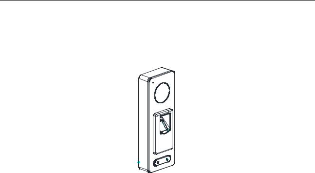
DS-K1T501SF is a series video access control terminal with multiple advanced technologies including fingerprint recognition, face detection, Wi-Fi, smart card recognition, and HD camera (2 MP optional). It is equipped with fingerprint recognition module (supporting 1:1 mode and 1:N mode), and supports offline operation.
1.2 Main Features
Doorbell ringtone settings function
Stand-alone settings for the terminal
Transmission modes of wired network (TCP/TP), Wi-Fi, RS-485, and Wiegand
Face detection and picture capturing function implemented by built-in camera (2 MP optional)
Supports RS-485 communication for connecting external card reader
Supports working as a card reader, and supports Wiegand interface and RS-485 interface for accessing the controller
Supports EHome protocol
Max. 50,000 cards Max. 200,000 access control events records, and Max.3000 fingerprints storage
Adopts fingerprint module, supporting 1:N mode (fingerprint, card + fingerprint) and 1:1 mode (card + fingerprint)
Supports multiple authentication modes including card, fingerprint, card + fingerprint, card + password, fingerprint + password, card + fingerprint + password, and so on.
Supports Mifare card/ QR Code reading
Tampering detection, unlocking overtime alarm, invalid card swiping over times alarm, duress card alarm, and so on
Supports security door control unit connection
9
Video Access Control Terminal·User Manual
Protection level: IP65
Data can be permanently saved after power-off
10
Video Access Control Terminal·User Manual
Chapter 2 Appearance
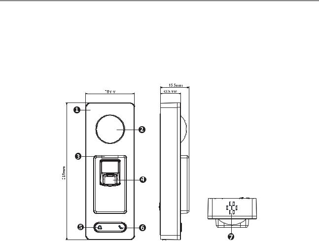
2.1 Appearance of DS-K1T501SF Model
Please refer to the following content for detailed information of the DS-K1T501SF model.
Table 2-1 Description of DS-K1T501SF Series Model
No. |
Description |
1 |
Mic |
2 |
Camera |
3 |
LED Indicator |
4 |
Fingerprint Scanner and Card Swiping Area |
5 |
Doorbell Button |
6 |
Voice Talk Button |
7 |
Loud Speaker |
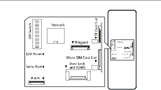
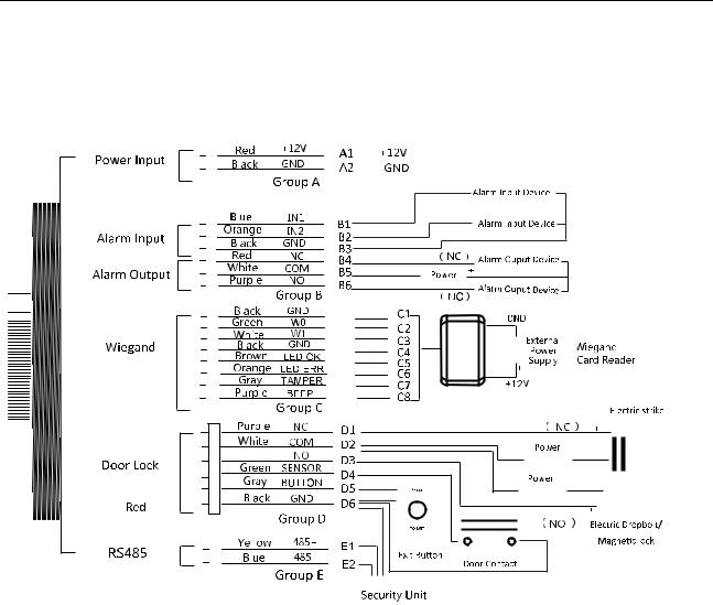
2.2 Video Access Control Terminal Connector
The video access control terminal connector is as follows:
11
Video Access Control Terminal·User Manual
12
Video Access Control Terminal·User Manual
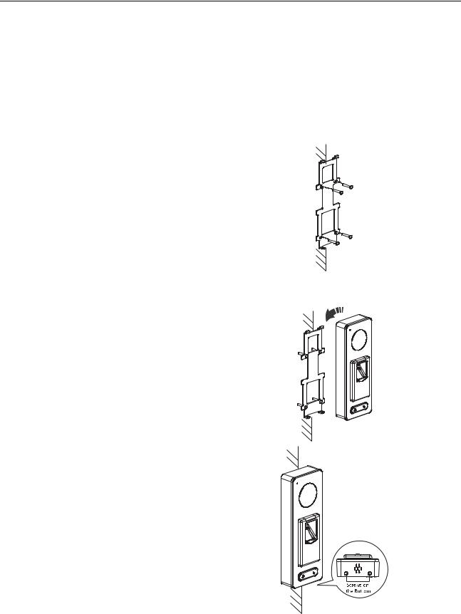
Chapter 3 Installation
Before You Start:
Make sure that the device in the package is in good condition and all the assembly parts are included.
Make sure that the wall is strong enough to withstand three times the weight of the terminal.
Set the DIP address before installation.
Steps:
1. Connect the cables with the connecter on the rear panel of the device. Route the cables through the cable hole of the mounting plate. The cable holes are on the right side, left side and lower side of the rear cover. If the right/left side cable hole is selected, remove the plastic sheet of the cable hole.
2.Secure the mounting plate on the wall with 4 supplied screws.
3. Connect the corresponding cables.
4. Push the terminal in the mounting plate from bottom up.
5. Tighten the screws on the bottom of the terminal to fix the terminal on the mounting plate and complete the installation.
13

Video Access Control Terminal·User Manual
Chapter 4 Terminal Connection
14

Video Access Control Terminal·User Manual
Table 4-1 Terminal Description
|
Group |
|
|
No. |
|
|
Function |
|
|
Color |
|
|
Terminal |
|
|
Description |
|
|
|
|
|
|
|
|
|
|
Name |
|
|
|
|||||
|
|
|
|
|
|
|
|
|
|
|
|
|
|
|
|
|
|
|
|
|
|
A1 |
|
|
|
|
Red |
|
+12V |
|
12V DC Power |
||||
|
Group A |
|
|
Power Input |
|
|
|
Supply |
|||||||||
|
|
|
|
|
|
|
|
|
|
|
|
||||||
|
|
|
|
|
|
|
|
|
|
|
|
|
|
||||
|
|
|
|
A2 |
|
|
|
|
Black |
|
GND |
|
GND |
||||
|
|
|
|
|
|
|
|
|
|
|
|
||||||
|
|
|
|
|
|
|
|
|
|
|
|
|
|
||||
|
|
|
|
B1 |
|
|
|
|
Yellow |
|
IN1 |
|
Alarm Input 1 |
||||
|
|
|
|
B2 |
|
Alarm Input |
|
Orange |
|
IN2 |
|
Alarm Input 2 |
|||||
|
Group B |
|
B3 |
|
|
|
|
Black |
|
GND |
|
GND |
|||||
|
|
B4 |
|
|
|
|
Red |
|
NC |
|
Alarm Output |
||||||
|
|
|
|
|
|
|
|
|
|
||||||||
|
|
|
|
B5 |
|
Alarm Output |
|
White |
|
COM |
|
||||||
|
|
|
|
|
|
|
|
Wiring |
|||||||||
|
|
|
|
B6 |
|
|
|
|
Purple |
|
NO |
|
|||||
|
|
|
|
|
|
|
|
|
|
|
|
||||||
|
|
|
|
C1 |
|
|
|
|
Black |
|
GND |
|
GND |
||||
|
|
|
|
|
|
|
|
|
|
|
|
|
|
|
|
|
|
|
|
|
|
C2 |
|
|
|
|
Green |
|
W0 |
|
Wiegand Wiring 0 |
||||
|
|
|
|
|
|
|
|
|
|
|
|
||||||
|
|
|
|
|
|
|
|
|
|
|
|
|
|
|
|
|
|
|
|
|
|
C3 |
|
|
|
|
White |
|
W1 |
|
Wiegand Wiring 1 |
||||
|
|
|
|
|
|
|
|
|
|
|
|
||||||
|
|
|
|
|
|
|
|
|
|
|
|
|
|
||||
|
|
|
|
C4 |
|
|
|
|
Black |
|
GND |
|
GND |
||||
|
Group C |
|
C5 |
|
Wiegand |
|
Brown |
|
LED-OK |
|
Wiegand |
||||||
|
|
|
|
|
|
Authenticated |
|||||||||||
|
|
|
|
|
|
|
|
|
|
|
|
|
|
|
|
||
|
|
|
|
|
|
|
|
|
|
|
|
|
|
|
|
Wiegand |
|
|
|
|
|
C6 |
|
|
|
|
Orange |
|
LED-ERR |
|
Authentication |
||||
|
|
|
|
|
|
|
|
|
|
|
|
|
|
|
|
Failed |
|
|
|
|
|
C7 |
|
|
|
|
Gray |
|
TAMPER |
|
Tampering Alarm |
||||
|
|
|
|
|
|
|
|
|
|
Wiring |
|||||||
|
|
|
|
|
|
|
|
|
|
|
|
|
|
|
|
||
|
|
|
|
C7 |
|
|
|
|
Purple |
|
BEEP |
|
Buzzer Wiring |
||||
|
|
|
|
D1 |
|
|
|
|
Purple |
|
NC |
|
|
|
|||
|
|
|
|
D2 |
|
|
|
|
White |
|
COM |
|
Lock Wiring |
||||
|
|
|
|
|
|
|
|
|
|
|
|
||||||
|
|
|
|
D3 |
|
|
|
|
Red |
|
NO |
|
|
|
|||
|
Group D |
|
D4 |
|
Lock |
|
Green |
|
SENSOR |
|
Door Magnetic |
||||||
|
|
|
|
|
|
Signal Input |
|||||||||||
|
|
|
|
|
|
|
|
|
|
||||||||
|
|
|
|
|
|
|
|
|
|
|
|
|
|
|
|
||
|
|
|
|
|
|
|
|
|
|
|
|
|
|
|
|
|
|
|
|
|
|
D5 |
|
|
|
|
Gray |
|
BUTTON |
|
Exit Door Wiring |
||||
|
|
|
|
|
|
|
|
|
|
|
|
||||||
|
|
|
|
|
|
|
|
|
|
|
|
|
|
||||
|
|
|
|
D6 |
|
|
|
|
Black |
|
GND |
|
GND |
||||
|
Group E |
|
E1 |
|
RS-485 |
|
Yellow |
485 + |
|
|
RS-485 Wiring |
||||||
|
|
E2 |
|
|
Blue |
485 - |
|
|
|||||||||
15
Video Access Control Terminal·User Manual
Chapter 5 Wiring Description
5.1 External Device Wiring Overview
Notes:
If set the working mode as the controller mode, the terminal can connect the RS-485 card reader or security control unit via RS-485 protocol. For details about wiring of RS-485 card reader, see 5.2 The Wiring of External RS-485 Card Reader.
If set the working mode as the controller mode, the terminal cannot connect the Wiegand card reader.
The security control unit can also connect the external devices. For details, see the specified user manual of security control unit.
16
Video Access Control Terminal·User Manual
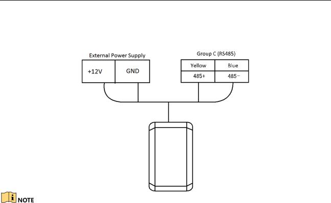
5.2 The Wiring of External RS-485 Card Reader
If set the working mode as the controller mode, the DIP switch No.6 should be set as OFF.
If set the working mode as card reader mode, the DIP switch No. from 1 to 4 should be set as OFF. Set the external card reader’s RS-485 DIP switch to 2. For details about DIP switch configuration, see Appendix B DIP Switch Introduction.
5.3 Card Reader Connection
The access control terminal can be switched into the card reader mode. It can access to the access control as a card reader, and supports Wiegand communication port and RS-485 communication port.
When the access control terminal works as a card reader, it only supports being connected to the controller, but does not support alarm input or output, or the connection of external devices.
17
Video Access Control Terminal·User Manual
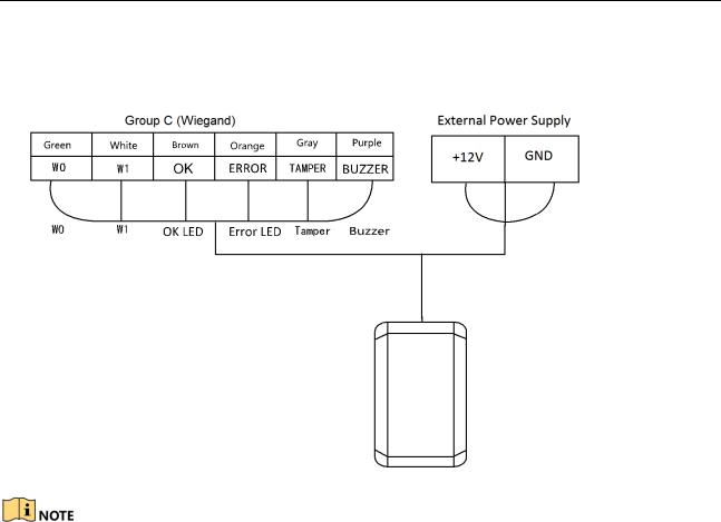
5.3.1 The Wiring of Wiegand
When the access control terminal works as a card reader, you must the WG_ERR, BUZZER and WG_OK interfaces if you want to control the LED and buzzer of the Wiegand card reader.
Set the working mode of the terminal as card reader, if the terminal is required to work as a card reader. The card reader mode support to communicate by Wiegand or RS-485.
The distance of Wiegand communication should be no longer than 80 m.
The external power supply and the access control terminal should use the same GND cable.
18
Video Access Control Terminal·User Manual
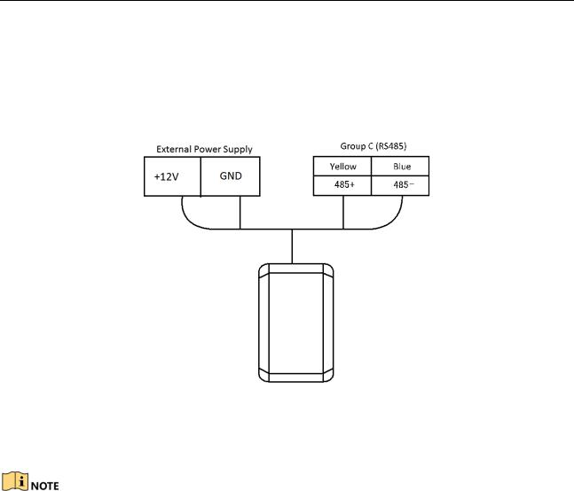
5.3.2 The Wiring of RS-485 Output
Set the working mode of the terminal as card reader, if the terminal requires working as a card reader.
When the access control terminal works as a RS-485 card reader, you can set the RS-485 address via the DIP switch.
The external power supply and the access control terminal should use the same GND cable.
19
Video Access Control Terminal·User Manual
Chapter 6 Activating the Access Control Terminal
Purpose:
You are required to activate the terminal first before using it. Activation via SADP, and Activation via client software are supported. The default values of the control terminal are as follows.
The default IP address: 192.0.0.64.
The default port No.: 8000.
The default user name: admin.
6.1 Activating via SADP Software
SADP software is used for detecting the online device, activating the device, and resetting the password.
Get the SADP software from the supplied disk or the official website, and install the SADP according to the prompts. Follow the steps to activate the control panel.
Steps:
1.Run the SADP software to search the online devices.
2.Check the device status from the device list, and select an inactive device.
3. Create a password in the password field, and confirm the password.
STRONG PASSWORD RECOMMENDED– We highly recommend you create a strong password of your own choosing (using a minimum of 8 characters, including upper case letters, lower case letters, numbers, and special characters) in order to increase the security of your product. And we recommend you reset your password regularly, especially in the high security system, resetting the password monthly or weekly can better protect your product.
4.Click Activate to activate the device.
5.Check the activated device, you can change the device IP address to the same network
20
Video Access Control Terminal·User Manual
segment with your computer by either modifying the IP address manually or checking the checkbox of Enable DHCP.
6. Input the password and click the Modify button to activate your IP address modification.
6.2 Activating via Client Software
The client software is versatile video management software for multiple kinds of devices.
Get the client software from the supplied disk or the official website, and install the software according to the prompts. Follow the steps to activate the control panel.
Steps:
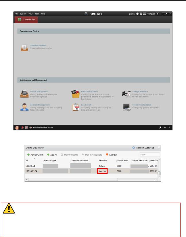
1.Run the client software and the control panel of the software pops up, as shown in the figure below.
21
Video Access Control Terminal·User Manual
2.Click Device Management to enter the Device Management interface.
3.Check the device status from the device list, and select an inactive device.
4.Check the device status from the device list, and select an inactive device.
5.Click the Activate button to pop up the Activation interface
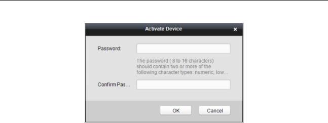
6.In the pop-up window, create a password in the password field, and confirm the password.
STRONG PASSWORD RECOMMENDED– We highly recommend you create a strong password of your own choosing (using a minimum of 8 characters, including upper case letters, lower case letters, numbers, and special characters) in order to increase the security of your product. And we recommend you reset your password regularly, especially in the high security system, resetting the password monthly or weekly can better protect your product.
22
Video Access Control Terminal·User Manual
7.Click OK button to start activation.
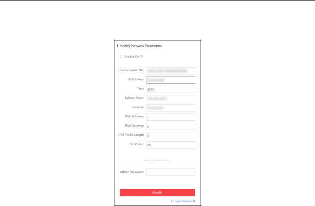
8.Click the Modify Netinfor button to pop up the Network Parameter Modification interface.
9.Change the device IP address to the same network segment with your computer by either modifying the IP address manually.
10.Input the password and click the OK button to save the settings.
23

Video Access Control Terminal·User Manual
Chapter 7Client Operation
You can set and operate the access control devices via the client software. This chapter will introduce the access control device related operations in the client software. For integrated operations, refer to User Manual of iVMS-4200 Client Software.
7.1 Function Module
Control Panel of iVMS-4200:
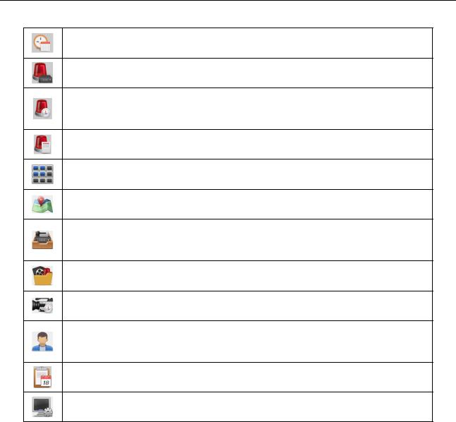
Menu Bar:
|
|
Open Image File |
|
Search and view the captured pictures stored on local |
|
|
|
||
|
|
|
PC. |
|
|
|
|
|
|
File |
|
Open Video File |
|
Search and view the video files recorded on local PC. |
|
|
Open Log File |
|
View the backup log files. |
|
|
Exit |
|
Exit the iVMS-4200 client software. |
|
|
Lock |
|
Lock screen operations. Log in the client again to |
|
|
|
unlock. |
|
|
|
|
|
|
|
|
Switch User |
|
Switch the login user. |
|
|
Import System Config |
|
Import client configuration file from your computer. |
System |
|
File |
|
|
|
|
Export System Config File |
|
Export client configuration file to your computer. |
|
|
|
|
Set the schedule for backing up the database |
|
|
Auto Backup |
|
including person, attendance data, and permission |
|
|
|
|
data automatically. |
24

Video Access Control Terminal·User Manual
|
|
|
|
1024*768 |
|
Display the window at size of 1024*768 pixels. |
|
|
|
|
|
||
|
|
|
|
1280*1024 |
|
Display the window at size of 1280*1024 pixels. |
|
|
|
|
1440*900 |
|
Display the window at size of 1440*900 pixels. |
|
|
|
|
1680*1050 |
|
Display the window at size of 1680*1050 pixels. |
|
|
|
|
Maximize |
|
Display the window in maximum mode. |
|
|
|
|
Control Panel |
|
Enter Control Panel interface. |
|
|
|
|
Main View |
|
Open Main View page. |
|
View |
|
|
Remote Playback |
|
Open Remote Playback page. |
|
|
|
Access Control |
|
Enter the Access Control Module. |
|
|
|
|
|
|
||
|
|
|
|
Status Monitor |
|
Enter the Status Monitor Module. |
|
|
|
|
Time and Attendance |
|
Enter the Time and Attendance Module. |
|
|
|
|
Security Control Panel |
|
Enter the Security Control Panel Module. |
|
|
|
|
Real-time Alarm |
|
Enter the Real-time Alarm Module. |
|
|
|
|
Video Wall |
|
Open Video Wall page. |
|
|
|
|
E-map |
|
Open E-map page. |
|
|
|
|
Auxiliary Screen Preview |
|
Open Auxiliary Screen Preview window. |
|
|
|
|
Device Management |
|
Open the Device Management page. |
|
|
|
|
Event Management |
|
Open the Event Management page. |
|
|
|
|
Storage Schedule |
|
Open the Storage Schedule page. |
|
|
|
|
Account Management |
|
Open the Account Management page. |
|
|
|
|
Log Search |
|
Open the Log Search page. |
|
|
|
|
System Configuration |
|
Open the System Configuration page. |
|
Tool |
|
|
Broadcast |
|
Select camera to start broadcasting. |
|
|
|
|
Device Arming Control |
|
Set the arming status of devices. |
|
|
|
|
Alarm Output Control |
|
Turn on/off the alarm output. |
|
|
|
|
Batch Wiper Control |
|
Batch starting or stopping the wipers of the devices. |
|
|
|
|
Batch Time Sync |
|
Batch time synchronization of the devices. |
|
|
|
|
Player |
|
Open the player to play the video files. |
|
|
|
|
Message Queue |
|
Display the information of Email message to be sent. |
|
|
|
|
Open Video Wizard |
|
Open the video guide for the video surveillance |
|
|
|
|
|
||
|
|
|
|
|
configuration. |
|
|
|
|
|
|
|
|
|
|
|
|
Open Video Wall Wizard |
|
Open the guide for the video wall configuration. |
|
|
|
|
Open Security Control |
|
Open the guide for the security control panel |
|
|
|
|
Panel Wizard |
|
configuration. |
|
|
|
|
Open Access Control and |
|
Open the guide for the access control and video |
|
Help |
|
|
Video Intercom Wizard |
|
intercom configuration. |
|
|
|
Open Attendance |
|
Open the guide for the time and attendance |
|
|
|
|
|
|
||
|
|
|
|
Wizard |
|
configuration. |
|
|
|
|
User Manual (F1) |
|
Click to open the User Manual; you can also open the |
|
|
|
|
|
User Manual by pressing F1 on your keyboard. |
|
|
|
|
|
|
|
|
|
|
|
|
About |
|
View the basic information of the client software. |
|
|
|
|
Language |
|
Select the language for the client software and |
|
|
|
|
|
reboot the software to activate the settings. |
|
|
|
|
|
|
|
25
Video Access Control Terminal·User Manual
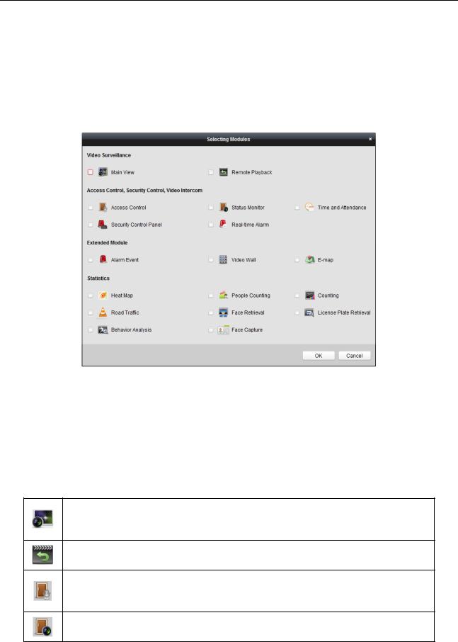
For the first time running the software, you can click  on the control panel to select the modules to display on the Operation and Control area of the control pane.
Steps:
1. Click  to pop up the following dialog.
2.Check the module checkboxes to display them on the control panel according to the actual needs.
3.Click OK to save the settings.
Notes:
After adding the access control device in Device Management module, the Access Control, Status, and Time and Attendance module will be displayed on the control panel automatically.
After adding the security control panel in Device Management module, the Security Control
Panel and Real-time Alarm modules will be displayed on the control panel automatically. The iVMS-4200 client software is composed of the following function modules:
The Main View module provides live view of network cameras and video encoders, and supports some basic operations, such as picture capturing, recording, PTZ control, etc.
The Remote Playback module provides the search, playback, export of video files.
The Access Control module provides managing the organizations, persons, permissions, and advanced access control functions.
Provides video intercom function.
The Status Monitor module provides monitoring and controlling the door status, viewing the real-time card swiping records and access control events.
26
Video Access Control Terminal·User Manual
The Time and Attendance module provides setting the attendance rule for the employees and generating the reports.
The Security Control Panel module provides operations such as arming, disarming, bypass, group bypass, and so on for both the partitions and zones.
The Real-time Alarm module provides displaying the real-time alarm of security control panel, acknowledging alarms, and searching the history alarms.
The Alarm Event module displays the alarm and event received by the client software.
The Video Wall module provides the management of decoding device and video wall and the function of displaying the decoded video on video wall.
The E-map module provides the displaying and management of E-maps, alarm inputs, hot regions and hot spots.
The Device Management module provides the adding, modifying and deleting of different devices and the devices can be imported into groups for management.
The Event Management module provides the settings of arming schedule, alarm linkage actions and other parameters for different events.
The Storage Schedule module provides the schedule settings for recording and pictures.
The Account Management module provides the adding, modifying and deleting of user accounts and different permissions can be assigned for different users.
The Log Search module provides the query of system log files and the log files can be filtered by different types.
The System Configuration module provides the configuration of general parameters, file saving paths, alarm sounds and other system settings.
The function modules are easily accessed by clicking the navigation buttons on the control panel or by selecting the function module from the View or Tool menu.
You can check the information, including current user, network usage, CPU usage, memory usage and time, in the upper-right corner of the main page.
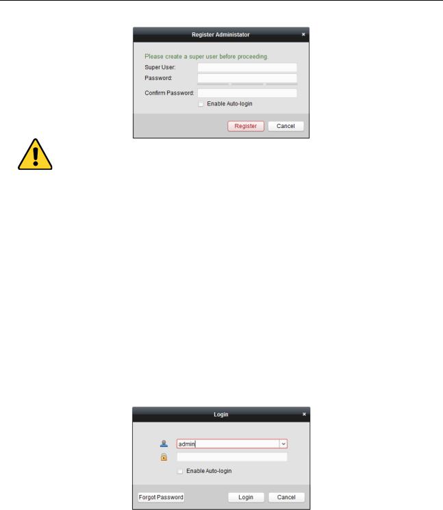
7.2 User Registration and Login
For the first time to use iVMS-4200 client software, you need to register a super user for login.
Steps:
1.Input the super user name and password. The software will judge password strength automatically, and we highly recommend you to use a strong password to ensure your data security.
2.Confirm the password.
3.Optionally, check the checkbox Enable Auto-login to log into the software automatically.
4.Click Register. Then, you can log into the software as the super user.
27
Video Access Control Terminal·User Manual
A user name cannot contain any of the following characters: / \ : * ? “ < > |. And the length of the password cannot be less than 6 characters.
For your privacy, we strongly recommend changing the password to something of your own choosing (using a minimum of 8 characters, including upper case letters, lower case letters, numbers, and special characters) in order to increase the security of your product.
Proper configuration of all passwords and other security settings is the responsibility of the installer and/or end-user.
When opening iVMS-4200 after registration, you can log into the client software with the registered user name and password.
Steps:
1.Input the user name and password you registered.
Note: If you forget your password, please click Forgot Password and remember the encrypted string in the pop-up window. Contact your dealer and send the encrypted string to him to reset your password.
2.Optionally, check the checkbox Enable Auto-login to log into the software automatically.
3.Click Login.
After running the client software, you can open the wizards (including video wizard, video wall wizard, security control panel wizard, access control and video intercom wizard, and attendance wizard), to guide you to add the device and do other settings and operations. For detailed configuration about the wizards, please refer to the Quick Start Guide of iVMS-4200.
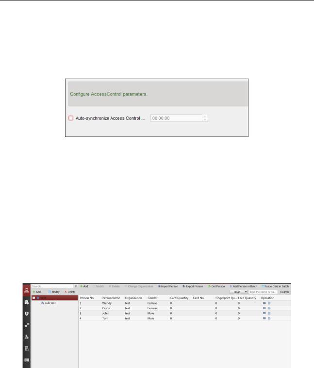
7.3 System Configuration
Purpose:
You can synchronize the missed access control events to the client.
28
Video Access Control Terminal·User Manual
Steps:
1.Click Tool – System Configuration.
2.In the System Configuration window, check the Auto-synchronize Access Control Event checkbox.
3.Set the synchronization time.
The client will auto-synchronize the missed access control event to the client at the set time.
7.4 Access Control Management
Purpose:
The Access Control module is applicable to access control devices and video intercom. It provides multiple functionalities, including person and card management, permission configuration, access control status management, video intercom, and other advanced functions.
You can also set the event configuration for access control and display access control points and zones on E-map.
Note: For the user with access control module permissions, the user can enter the Access Control module and configure the access control settings.
Click  in the control panel, and check Access Control to add the Access Control module to the control panel.
Click  to enter the Access Control module.
Before you start:
For the first time opening the Access Control module, the following dialog will pop up and you are required to select the scene according to the actual needs.
Non-residence: You can set the attendance rule when adding person, while set the access control parameters.
Residence: You cannot set the attendance rule when adding person.
29
 Loading...