


DS-3E0109XX
Applicable Models
This manual is applicable to DS-3E0105XX and DS-3E0109XX series 100M long-range PoE
switch.
Symbol Convenons
The symbols that may be found in this document are defined as follows.
Symbol Descripon
Provides addional informaon to emphasize or
supplement important points of the main text.
Indicates a potenally hazardous situaon, which if not
avoided, could result in equipment damage, data loss,
performance degradaon, or unexpected results.
·
·During the installaon and ulizaon of the device, please strictly conform to electrical
safety rules in different naons and regions.
·Ensure to use the aached power adaptor only and not to change the adaptor randomly.
Please refer to specificaon table for specific requirements of power adaptor.
·If the product does not work properly, please contact your dealer or the nearest service
center. Never aempt to disassemble the camera yourself. (We shall not assume any
responsibility for problems caused by unauthorized repair or maintenance.)
·The device must be installed in machine room only, and only maintenance staff or
qualified person should access to the device.
·Do not touch the upper cover area of the device that may be overheated.
·Power must be shut down during cable connecon, device installaon and
dismantlement.
·You shall acknowledge that the use of the device with Internet access might be under
network security risks, please strengthen protecon for your personal informaon and
data security. If you find the device might be under network security risks, please contact
with us.
·Proper configuraon of all passports and other security sengs is the responsibility of
the installer, and you shall keep user name and passports properly.
·Please keep all original packing materials properly. If the product does not work
properly, pack the switch in its original packing materials for shipping. We shall not assume
any responsibility for damages caused by improper packing materials during shipping.
·Ensure that your devices powered via the PoE port have their shells protected and
fire-proofed, because the switches are not compliant with the Limited Power Source (LPS)
standard.
Indicates a hazard with a high level of risk, which if
not avoided, will result in death or serious injury.
1
Packing List
Switch x 1
Power Adapter x 1
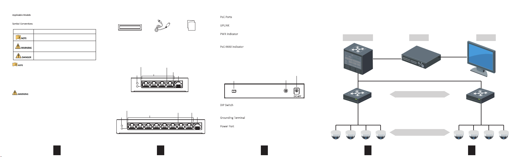
Interfaces
Front Panel
DS-3E0105XX Series:
PoE-MAX Indicator
PWR
Indicator
DS-3E0109XX Series:
PoE-MAX Indicator
PWR
Indicator
1 2 3 4 5 6 7 8 9
LINK/ACT Indicator
PoE Ports
1 2 3 4 5
LINK/ACT Indicator PoE Indicator
PoE Ports
2
Quick Start Guide x 1
PoE Indicator
UPLINK
UPLINK
PoE Ports
100M PoE ports connect to other PoE devices with network cable.
UPLINK
100M network port connects to other switches with network cable.
PWR Indicator
Solid means powered up normally. Unlit means no power supply
connected or power supply is abnormal.
PoE-MAX Indicator
Solid/flashing means the output power of the switch will reach the
upper limit, and the power supply may be abnormal if more devices
are connected. Unlit means power supplying is normal.
Rear Panel
DIP Switch
DIP Switch
On: Extend model is on, connecng PoE port 1-4 (4 ports), 1-8 (8 ports).
Off: Extend model is off.
Grounding Terminal
The grounding terminal connects with ground cable in case of lightning.
Power Port
Connect power port of the switch with power socket with power cord
to provide power to the switch.
Power Interface
Grounding Terminal
DC 48V
3
Device Connecon
Connect your devices according to your actual networking requirements.
Convergence Switch
Up to 250 m
4
NVR
100M PoE Switch
Camera
Monitor
5
 Loading...