


http://www.hikvision.com
Network Storage Product
Quick Start Guide
Technical Hotline: 400-700-5998

Introduction
Description
The storage system is a kind of high-performance and cost-effective Gigabit network storage
system and is mainly applicable to the medium and large-scale video surveillance system,
supporting storage for unstructured data and management for structured data. The system
can be applied in various fields, like surveillance industry, government, energy industry and so on.
Features:
Support CVR/SAN/NAS storage mode.
Support iSCSI/CIFS/NFS/FTP/HTTP/AFP /RTSP protocol.
Full-modularization and cable-less design.
General SBB2.0 standard structure.
Support two controllers and redundant power supply.
Support RAID0, RAID1, RAID3, RAID5, RAID6, RAID10 and RAID50 mode.
HDD hot-spare capability.
Support extending gigabit by using MEZZANINE. Up to 8 gigabit Ethernet port.
Support extending storage capacity and cascading storage enclosure.
Intelligent environment control and green energy saving.
The manual mainly introduce the basic using knowledge for working environment, Installation,
HDD Installation, system monitor, network configuration, Array configuration and public service
configuration. It is highly recommended to read the manual before using the storage system. For
detailed information of system configuration, please refer to system user manual.
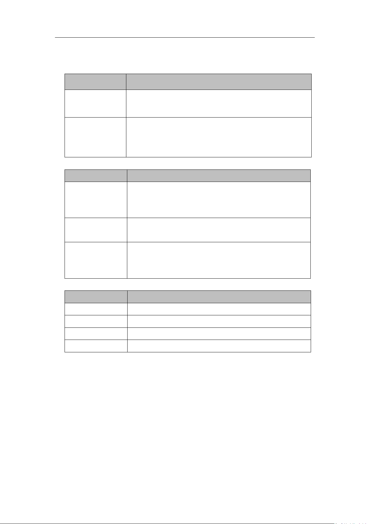
Conventions
Description
Explanation
“ ”
Means the control name and data sheet in a certain interface. For
example, click “OK” means to click the OK button.
>
Uses “>” to describe multilevel menu. For example, “File > Add >
Folder” represents clicking the “Folder” in the “add” submenu
under the “File ” menu.
Description
Explanation
Character with “”
Indicates the name of the button. For example “Enter ”, “ Tab ”,
“ Backspace ” and “ a ” represent respectively enter button, tab
button, backspace button and a lowercase.
“key1+key2”
Presses several buttons simultaneously. For example, “Ctrl+Alt+A”
means to press “Ctrl”, “Alt” and “A” the three keys at a time.
“key1, key2”
Means press a key and release, and press the second key. For
example, “Alt, F” means press “Alt” key and release, and press the
“F” key.
Description
Explanation
Click
Press and release the left button of mouse quickly.
Double-click
Quick press twice in the left button of mouse.
Right-click
Press and release the right button of mouse quickly.
Drag
Press and hold the left button, and move the mouse.
1. Conventions in graphical interface element
2. Conventions for keyboard operation
3. Conventions for mouse operation

Update Record
Version
Revise Time
Revise Content
V1.0
2014.9
New manual created.

Table of Contents
CHAPTER 1 INTRODUCTION OF SECURITY AND SERVICE ....................................... 1
1.1 SECURITY INFORMATION AND DISCLAIMER .............................................................................................. 1
1.2 SECURITY SYMBOLS ............................................................................................................................ 1
1.3 PRODUCT SERVICE ............................................................................................................................. 2
CHAPTER 2 WORKING ENVIRONMENT AND INSTALLATION ................................. 3
2.1 ENVIRONMENT OF EQUIPMENT ROOM .................................................................................................. 3
2.2 INSTALLATION AND INITIAL POWER-ON .................................................................................................. 4
2.3 NOTES FOR INSTALLATION .................................................................................................................... 4
2.4 DEVICE RELIABILITY ............................................................................................................................ 4
CHAPTER 3 HARDWARE INSTALLATION .................................................................... 6
3.1 STRUCTURE APPEARANCE OF 12 SLOTS MACHINE .................................................................................... 6
3.2 STRUCTURE APPEARANCE OF 24 SLOTS MACHINE .................................................................................... 9
3.3 STRUCTURE APPEARANCE OF 60 SLOTS MACHINE .................................................................................. 12
3.4 INSTALLING ACCESSORIES .................................................................................................................. 16
3.4.1 Installation Requirement ..................................................................................................... 16
3.4.2 Installing HDD ...................................................................................................................... 16
3.4.3 Power on/off ....................................................................................................................... 18
CHAPTER 4 CONFIGURING NETWORK PARAMETERS ............................................20
4.1 LOGIN ........................................................................................................................................... 20
4.2 CONFIGURING NETWORK PARAMETERS ................................................................................................ 20
4.2.1 Editing Basic Network Paremeters ...................................................................................... 20
4.2.2 Configuring Bonding Mode ................................................................................................. 21
4.2.3 Configuring Multi-NIC Bonding ........................................................................................... 22
4.2.4 Deleting Multi-bonding Mode ............................................................................................. 22
4.2.5 Network Connecting Principle ............................................................................................ 23
CHAPTER 5 CONFIGURING CVR ................................................................................24
5.1 CONFIGURATION REQUIREMENT ......................................................................................................... 24
5.2 CONFIGURING CLUSTER HEARTBEAT .................................................................................................... 24
5.3 CONFIGURING RESOURCE IP ADDRESS ................................................................................................. 26
5.4 CONFIGURING CVR ......................................................................................................................... 28
5.4.1 Quick Setting ....................................................................................................................... 28
5.4.2 Manual Configuration ......................................................................................................... 30
5.5 CONFIGURING RECORDING SCHEDULES ................................................................................................ 33
5.5.1 Entering CVR Sub-system .................................................................................................... 33

5.5.2 Adding Encoding Devices .................................................................................................... 34
5.5.3 Configuring Recording Schedules ........................................................................................ 35
5.6 REVIEWING RECORDING FUNCTION ..................................................................................................... 35
5.6.1 Live View ............................................................................................................................. 35
5.6.2 Searching Recording Files .................................................................................................... 37
5.6.3 Playing Back Recording Files ............................................................................................... 38
CHAPTER 6 CREATING AND MANAGING ARRAY ....................................................39
6.1 DISK MANAGEMENT ........................................................................................................................ 39
6.1.1 Disk Information .................................................................................................................. 39
6.1.2 Checking Disk ...................................................................................................................... 39
6.2 ARRAY MANAGEMENT ...................................................................................................................... 41
6.2.1 Creating Array ..................................................................................................................... 41
6.2.2 Rebuilding Array .................................................................................................................. 42
6.2.3 Checking and Repairing Array ............................................................................................. 46
6.3 STORAGE POOL MANAGEMENT .......................................................................................................... 49
6.3.1 Adding Storage Pool ............................................................................................................ 49
CHAPTER 7 CONFIGURING ISCSI ...............................................................................51
7.1 CREATING ARRAY AND STORAGE POOL ................................................................................................. 51
7.2 CREATING ISCSI VOLUME .................................................................................................................. 51
7.3 ENABLING ISCSI .............................................................................................................................. 51
7.4 INSTALLING MPIO IN WINDOWS 2008 ............................................................................................... 52
7.5 CREATING ISCSI CONNECTION IN WINDOWS 2008 ................................................................................ 56
7.6 CLIENT SIDE MAPPING/FORMATTING LOCAL ISCSI DISK ......................................................................... 61
7.7 ESTABLISHING ISCSI CONNECTION IN REDHAT 5 .................................................................................... 62
CHAPTER 8 MANAGING FAILURE DISK ....................................................................64
8.1 DISK ALARM ................................................................................................................................... 64
8.2 EXCHANGING FAILURE DISKS .............................................................................................................. 64
CHAPTER 9 NOTES ......................................................................................................66
IDENTIFIER LIST OF REGULATED SUBSTANCES AND ELEMENTS ..............................67
WARRANTY CARD A .......................................................................................................68
WARRANTY SERVICE .......................................................................................................69
WARRANTY CARD B ........................................................................................................70
Quick Start Guide
The product, as an A class product, may cause radio jamming. In this situation, you
should take effective actions.
Using an unsuitable battery may result in explosion, please handle the exhausted
battery according to the rules.
The product is only suitable to sell to region at an altitude below 2000 meters.
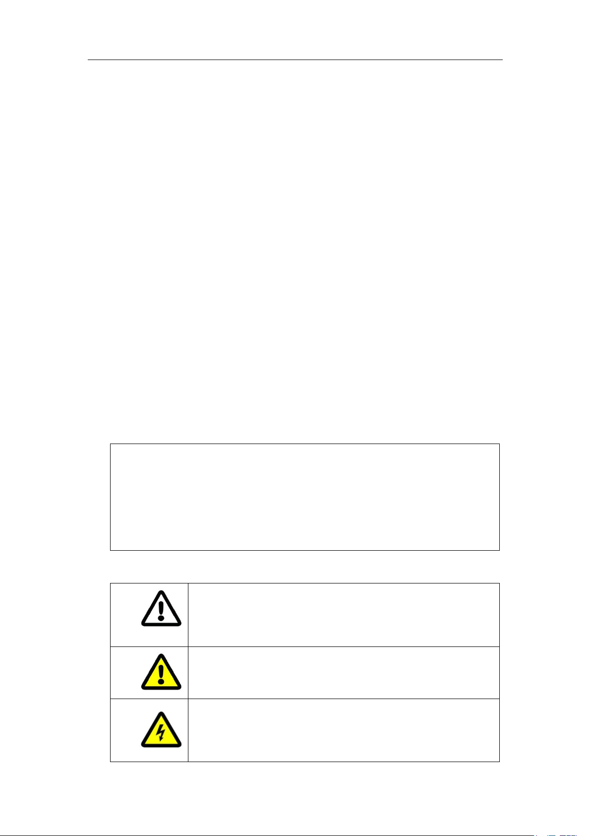
Attention Symbol: it represents potential risks. Ignoring the attention
may result in device damage, data loss, performance degradation or
some unpredictable results.
Alarm Symbol: it represents moderate or low grade potential risks. If
you cannot avoid, it may result in mild or moderate personal injury.
Danger Symbol: it represents moderate or low grade potential risks. If
you ignore or cannot avoid the risk, it may result in death or serious
injury.
Chapter 1 Introduction of Security and
Service
1.1 Security Information and Disclaimer
(1) In order to ensure the security of user and device, please obey the precautions in the user
manual and the symbol in the device during the installation, operation and maintenance.
Besides the content of attention, warning and danger in the use manual, you should also
consider local regulations and specifications.
(2) The product is an industrially specialized equipment which has high voltage and current. It
should be installed and maintained by qualified technician. Our company takes no
responsibility for any consequences resulted from violating security requirement, criterion
for design, local regulations and specifications.
(3) This manual may contain technical inaccuracies, discrepancies with product feature or
operation, or literal errors. We update content of the manual according to the enhancement
of our product. And we also regularly update the product and procedure in the manual.
Without further notice, the updated contents are added to the new version.
(4) Special statement:
1.2 Security Symbols
1

Quick Start Guide
Disk Plugging Alarm Symbol: it prompts you do not plug the disk.
Electrostatic Protection Symbol: it prompts you to wear an
anti-electrostatic wrist strap or gloves, to avoid electrostatic circuit
board be damaged.
1.3 Product Service
For general auxiliary software tools, please refer to online help page of the storage system.
2

Quick Start Guide
Chapter 2 Working Environment and
Installation
Devices described in this manual should be installed in the standard equipment room.
2.1 Environment of Equipment Room
1. Power Supply System
The storage system is sensitive to the change of a voltage, and an excessively high or low voltage,
or a sudden change of the voltage may delete the data in the memory or even cause the damage
of the components. To avoid of such damage, you must ensure the power supply is stable and
grounded. You are recommended to use the UPS, or the multiple power supply if permitted.
Requirements:
The voltage should be in the range of 110V to 220V(allowed range is between -4% to +4%),
and the change must be in the range of 110V to 220V(allowed range is between -15% to
+15%); Frequency: 50~60Hz+/-0.5Hz;
Make correct neutral line and GND line connections, and the voltage between them must be
less than 1V.
Grounding for AC power supply system: ensure the GND line is properly connected. The
grounding for the chassis is recommended.
Grounding for DC power supply system: the chassis must be properly grounded.
Connect all power cords before applying power to the redundant power supply module.
The storage system supports management for some UPS models.
2. Control of Working Environment
The over-high or over-low temperature and other unsatisfying installation and running
environment factors may cause failures of the chip and mechanical components of the device,
and thus they affect the stable and reliable running of the device as well as the data safety on the
disks. Please follow the measurements shown below to take proper measurements:
Use an air conditioner to control the temperature and the humidity at least 2 or 3 days
before installing the device.
The working environment of the device should meet the temperature of 23 ºC±2 ºC,
humidity of 50%Rh ± 5%Rh and the temperature change rate of <5 ºC/h with
non-condensing.
The floor in the equipment room must be capable of loading more than 600kg/m
height between the floor and the ceiling must be more than 2.7 m. The loading capability of
3
2
, and the

Quick Start Guide
the rack can be computed in 10 kg/U, e.g., for a 4U chassis, the required loading capability of
the rack is 40 kg.
Ensure adequate air ventilation of the rack.
Close all the doors and windows to prevent the dust or use a dust-filtering ventilation device.
The dust particulate (≥5μm) must be less than 18,000 particulate / (dm)³.
In a conditions of non-working status of the device, the horizontal and vertical vibration
acceleration value of the floor surface of equipment room must be lower than 0.5m/S².
The rack or surface on which the device is installed must be properly grounded, and ensure
that each device is grounded as well. The resistance between the device casing and the
ground must be less than 4Ω.
2.2 Installation and Initial Power-on
The device shall be placed on the fixed flat surface. Tilting surface is not allowed.
You can use the standard plate in the industrial cabinet or use the guide rail (not provided)
to install the device to the rack. It is recommended to use the bolts to fix the device to the
rack through the mounting screw holes on the rack.
Connect all the power cords of the device to the power socket and wait for 12 hours before
starting up. The temperature of the device and the equipment room must be consistent to
prevent the damage caused by a huge temperature difference.
If the device has been transported and stored for more than 10 days; perform the previous
operation and then start up and run the device for 30 minutes without the hard disks. And
then you shut down the device, insert the hard disks and start the device again.
2.3 Notes for Installation
The device is a high-precision equipment. Please keep stable and gentle when moving it.
Installation and running environment must meet standards. Take regular investigations and
records for the equipment room, or apply a remote monitoring for the working status of the
device.
Do not unplug the power cord when the device is running.
In case of alarm beeper produced during the system running, please take immediate check
and solution.
2.4 Device Reliability
To enhance the reliability of the operating of the device, you can take the following measures:
4

Quick Start Guide
Use the mobile alarm software installed on the storage system. When an alarm event occurs,
the alarm message will be sent to your mobile phone as SMS.
Add the Email alarm software module. When the device runs abnormally, the alarm
information can be sent to the dedicated Email address.
Use the StorOS Manager software to realize the online management and monitor for all the
storage devices.
Connect to the NTP server to adjust time for the storage server to avoid the inaccuracy of
record time or record loss.
Add a SNMP software module, the system alarm can be sent to the SNMP client on a PC.
5
Quick Start Guide
Chapter 3 Hardware Installation
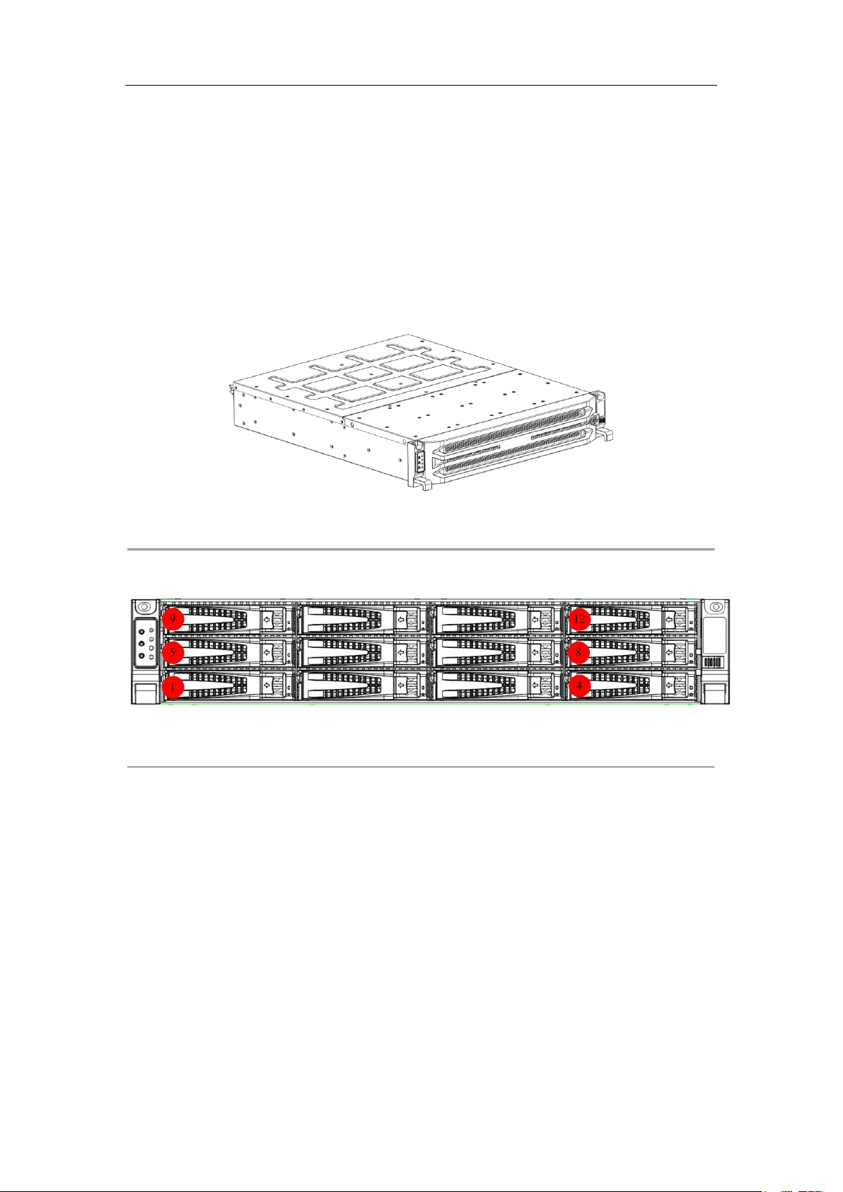
3.1 Structure Appearance of 12 Slots Machine
The hardware system adopts rack-mounted chassis which provides LED indicators for the status of
power, network and HDD.
1. Front Panel
Figure 3-1 Front Panel of Deivce
2. Description and Front Panel of Chassis Front Panel
Figure 3-2 Front View of Chassis Front Panel
Hard diskes of 3.5 inches are supported. Slot order obeys the principle of left to right and bottom
to top, as shown above. The HDDs in bottom floor, from left to right, are HDD ①~④. The HDDs
in second floor, from left to right, are HDD ⑤~⑧. And so on.
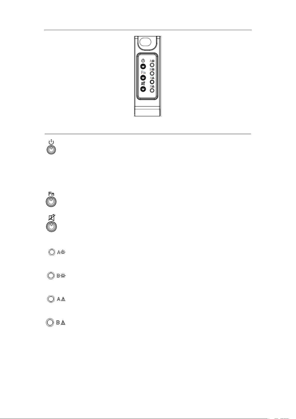
3. Description of Buttons in Front Panel
6
Quick Start Guide
Figure 3-3 Front Panel Diagram
: Power switch and green light power indicator. To turn on the system, press the button.
And to turn off the system, press and hold the button for 4 seconds. And you can also force to
power off the system by pressing and holding the button for 15 seconds. The indicator shows
green when the system is running.
: Function button and blue light indicator for locating function.
: Mute button and red light alarm indicator for clearing beep alarm sound and indicating
system alarm.
: Green light power indicator for controller A. When controller A is connected and is in
the running status, the indicator is green.
: Green light power indicator for controller B. When controller B is connected and is in
the running status, the indicator is green.
: Red light fault indicator. When controller A is connected and is in a failure status, the
indicator will flash. If the controller A is not connected, the indicator light off.
: Red light fault indicator. When controller B is connected and is in a failure status, the
indicator will flash. If the controller B is not connected, the indicator light off.
7
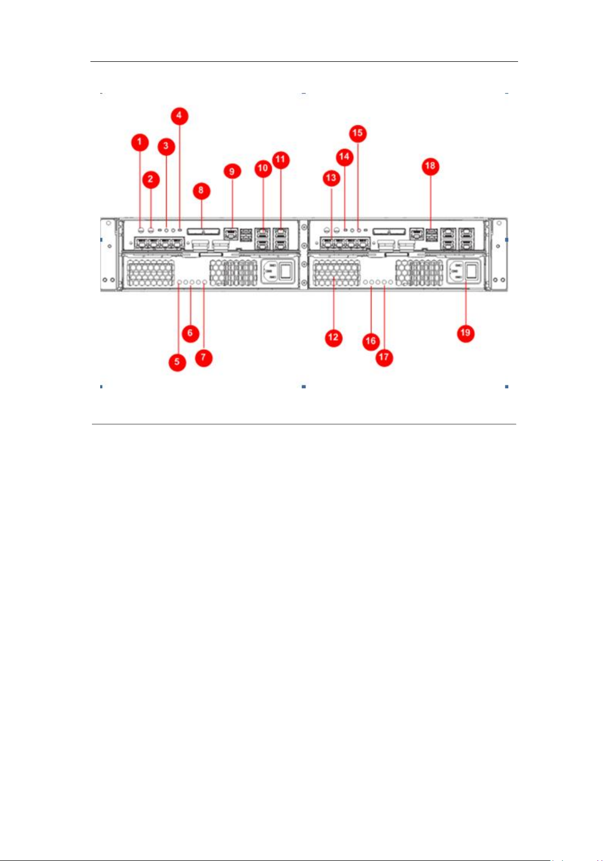
4. Description of Rear Panel
Quick Start Guide
Figure 3-4 Rear Panel of Device
① COM 2 ② COM 1 ③ Function Indicator
④ Power Switch ⑤ Standby Good LED(Green) ⑥ Service Action LED(Blue)
⑦ AC Good LED(Green) ⑧ Expansion Interface ⑨ Network Manage Port
⑩ Data NIC 2, 4 ⑪ Data NIC 1, 3 ⑫ Fan
⑬ Network Expansion Interface 1-4 ⑭ Restart Button ⑮ Power Indicator(Green)
⑯ DC Good LED(Green) ⑰ Power Fault(Amber) ⑱ USB Interface
⑲ AC Power Supply and Power Switch
Notes:
① COM 2 is UPS interface. Using a serial port line to connect the UPS interface and UPS
power supply.
② COM 1 is the system display interface. To visit the storage system by PC, use a serial port
line to connect the interface and PC.
⑬Network Expansion Port 1-4 can be 1000M/10G or fiber port according to real situation.
⑤, ⑥, ⑦, ⑯ and ⑰ are five power indicators. These statuses of indicators represent
different power statuses. For detailed information of the statuseed, please consult our
technical support staffs for details.
8
Quick Start Guide
3.2 Structure Appearance of 24 Slots Machine
The hardware system adopts rack-mounted chassis which provides LED indicators for the status of
power, network and HDD.
1. Front Panel
Figure 3-5 Front Panel of Device
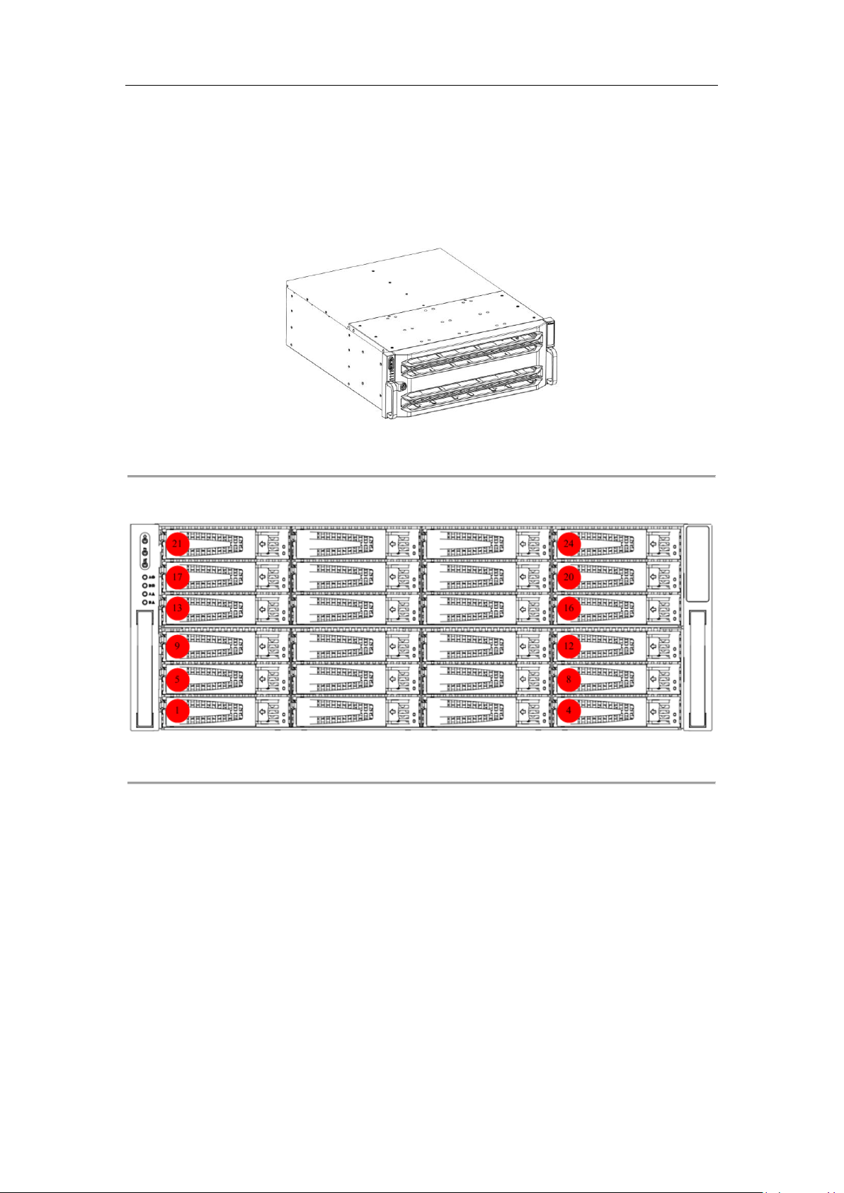
2. Description and Front Panel of Chassis Front Panel
Figure 3-6 Front Panel of Chassis Front Panel
Hard diskes of 3.5 inches are supported. Slot order obeys the principle of left to right and bottom
to top, as shown above. The HDDs in bottom floor, from left to right, are HDD ①~④. The HDDs
in second floor, from left to right, are HDD ⑤~⑧. And so on.
3. Description of Buttons in Front Panel
9
Quick Start Guide
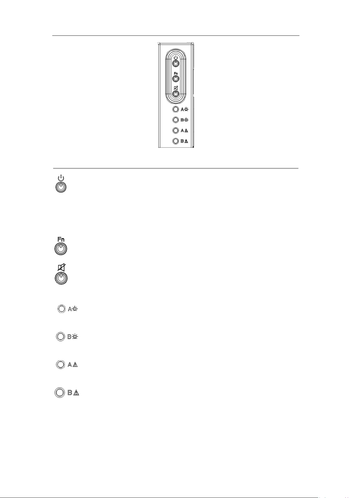
Figure 3-7 Front Panel Diagram
: Power switch and green light power indicator. To turn on the system, press the button.
And to turn off the system, press and hold the button for 4 seconds. And you can force to power
off the system by pressing and holding the button for 15 seconds. The indicator shows green
when the system is running.
: Function button and blue light indicator for locating function.
: Mute button and red light alarm indicator for clearing beep alarm sound and indicating
system alarm.
: Green light power indicator for controller A. When controller A is connected and is in
the running status, the indicator is green.
: Green light power indicator for controller B. When controller B is connected and is in
the running status, the indicator is green.
: Red light fault indicator. When controller A is connected and is in a failure status, the
indicator will flash. If the controller A is not connected, the indicator light off.
: Red light fault indicator. When controller B is connected and is in a failure status, the
indicator will flash. If the controller B is not connected, the indicator light off.
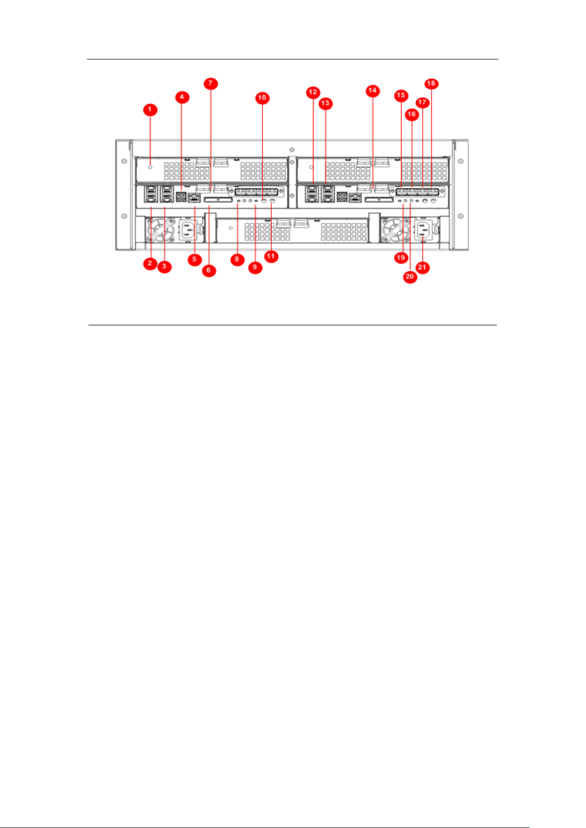
4. Description of Rear Panel
10
Quick Start Guide
Figure 3-8 Rear Panel of Device
① Fan Fault Alarm Indicator② Data NIC 1 ③ Data NIC 2
④ USB Interface ⑤ Network Manage Port ⑥ Storage Enclosure Interface
⑦ Controller A ⑧ Function Button ⑨ Power Switch
⑩ COM 1 ⑪ COM 2 ⑫ Data NIC 3
⑬ Data NIC 4 ⑭ Controller B ⑮ Expansion Interface 1
⑯ Expansion Interface 2 ⑰ Expansion Interface 3 ⑱ Expansion Interface 4
⑲ Power Indicator ⑳ FN Locating Indicator ○21 Power Supply Interface
Notes:
Connect the storage enclosure to the left ⑥ Storage Enclosure Interface.
⑩ COM 1 is the system display interface. To visit the storage system by PC, use a serial port
line to connect the interface and PC.
⑪ COM 2 is UPS interface. Using a serial port line to connect the UPS interface and UPS
power supply.
⑮Network Expansion Port 1-4 can be 1000M/10G or fiber port according to actuality.
The type of device support DC power supply(-40VDC to -72VDC). It needs exchange DC
power supply module respectively.
11
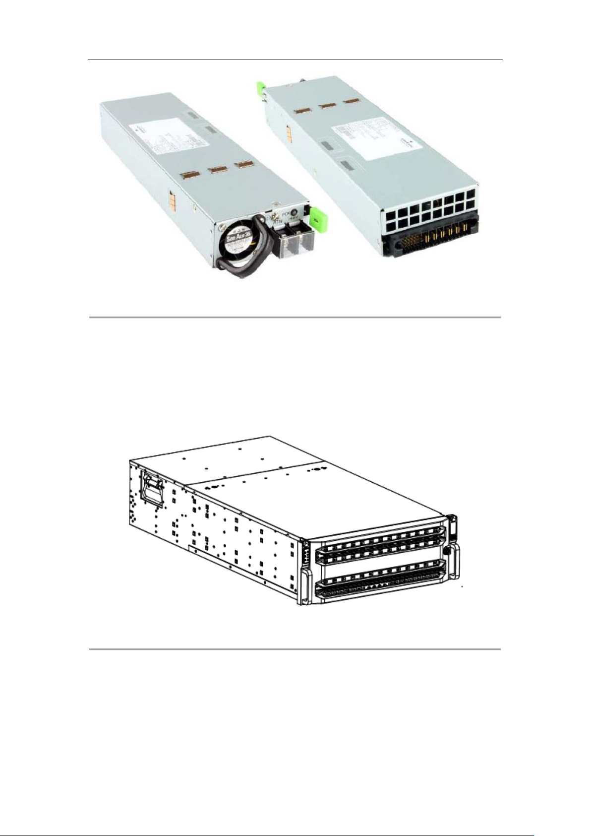
Quick Start Guide
Figure 3-9 DC Power Supply Module
3.3 Structure Appearance of 60 Slots Machine
The hardware system adopts rack-mounted chassis which provides LED indicators for the status of
power, network and HDD.
1. Front Panel
Figure 3-10 Front Panel of Device
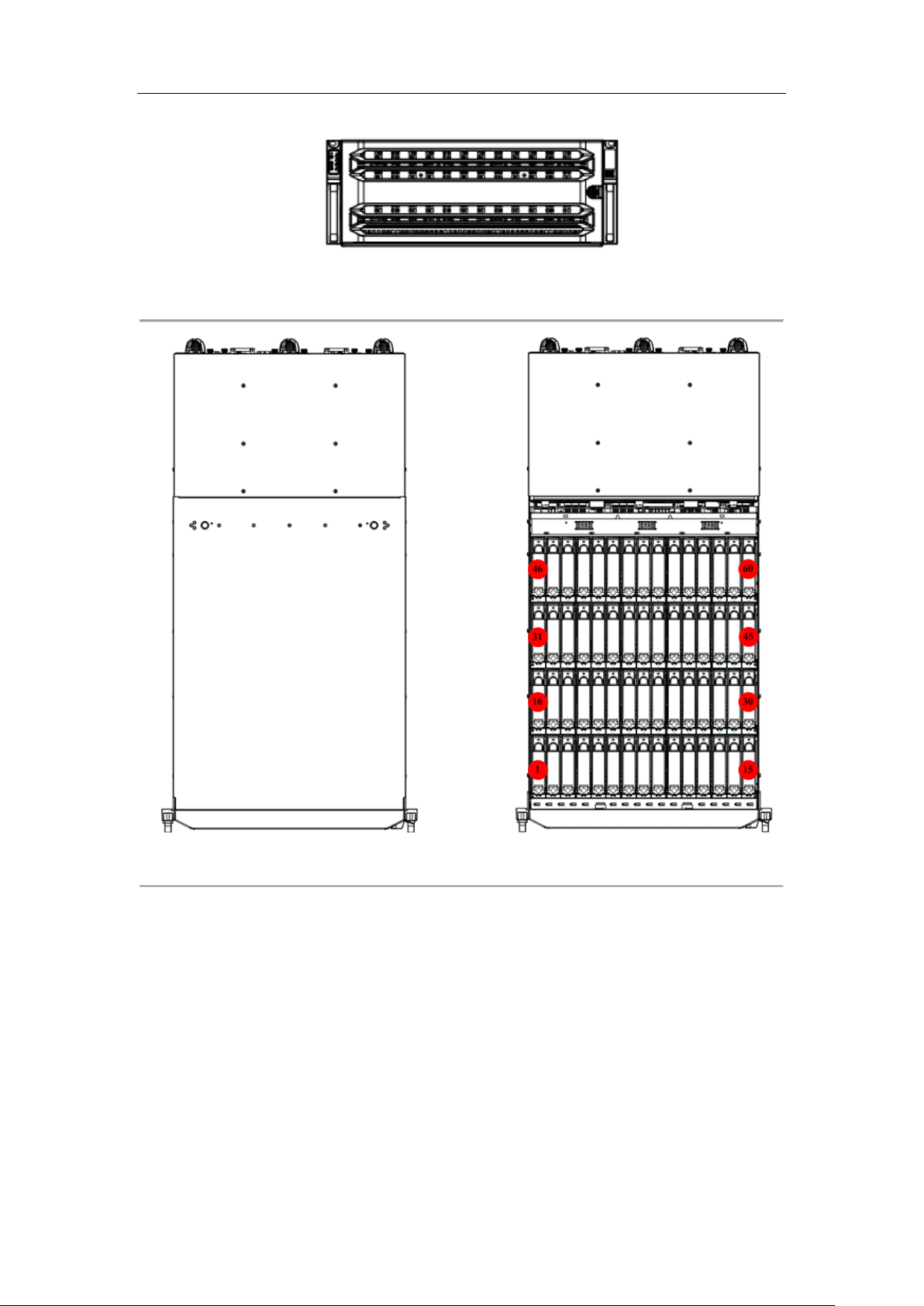
2. Description and Front Panel of Chassis Front Panel
12
Quick Start Guide
Figure 3-11 Front view of Chassis Front Panel
Figure 3-12 Top View of Device
Hard diskes of 3.5 inches are supported. Slot order obeys the principle of left to right and bottom
to top, as shown above. The HDDs in bottom floor, from left to right, are HDD ①~④. The HDDs
in second floor, from left to right, are HDD ⑤~⑧. And so on.
3. Description of Buttons in Front Panel
13

Quick Start Guide
Figure 3-13 Front Panel Diagram
: Power switch and green light power indicator. To turn on the system, press the button.
And to turn off the system, press and hold the button for 4seconds. And you can force to power
off the system by pressing and holding the button for 15 seconds. The indicator shows green
when the system is running.
: Function button and blue light indicator for locating function.
: Mute button and red light alarm indicator for clearing beep alarm sound and indicating
system alarm.
: Green light power indicator for controller A. When controller A is connected and is in
the running status, the indicator is green.
: Green light power indicator for controller B. When controller B is connected and is in
the running status, the indicator is green.
: Red light fault indicator. When controller A is connected and is in a failure status, the
indicator will flash. If the controller A is not connected, the indicator light off.
: Red light fault indicator. When controller B is connected and is in a failure status, the
indicator will flash. If the controller B is not connected, the indicator light off.
4. Decription of Rear Panel
14
Quick Start Guide
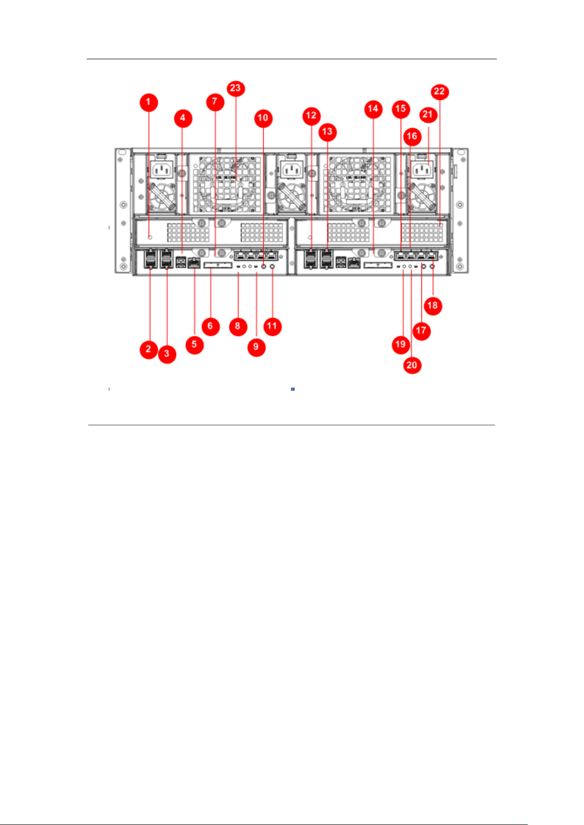
Figure 3-14 Rear View of Device
①Fan Fault Alarm Indicator ② Data NIC 1 ③ Data NIC 2
④ USB Interface ⑤ Network Manage Port ⑥ Storage Enclosure Interface
⑦ Controller A ⑧ Function Button ⑨ Power Switch
⑩ COM 1 ⑪ COM 2 ⑫ Data NIC 3
⑬ Data NIC 4 ⑭ Controller B ⑮ Expansion Interface 1
⑯ Expansion Interface 2 ⑰ Expansion Interface 3 ⑱ Expansion Interface 4
⑲ Power Indicator ⑳ FN Locating Indicator ○21 Power Supply Interface
22 Fan Module 1
○
Notes:
Connect the storage enclosure to the left ⑥ Storage Enclosure Interface.
⑩ COM 1 is the system display interface. To visit the storage system by PC, use a serial port
line to connect the interface and PC.
23 Fan Module 2
○
⑪ COM 2 is UPS interface. Using a serial port line to connect the UPS interface and UPS
power supply.
⑮-⑱Network Expansion Port 1-4 can be 1000M/10G or fiber port according to actuality.
15

Quick Start Guide
3.4 Installing Accessories
3.4.1 Installation Requirement
Before installation, please prepare the following equipment and accessories:
1. Power cord
2. Serial port line
3. Product Certification
4. Quick Operation Guide(including warrant card)
The following accessories are optional or user-provided:
1. Gigabit Ethernet switch (second-layer switch, user-provided)
2. Rack guide apparatus (optional)
Please check the following hardware connection
1. Power cord connection: connect the power cord to 110V~220VAC power supply.
2. Serial port: connect the serial port to operate initialization for the storage system (optional).
Note: before installing device, please wear a wrist strap and ensure it is correctly grounded.
3.4.2 Installing HDD
3.4.2.1 Selecting HDD Model
It is recommended to adopt the certificated professional HDD models so as to ensure the stable
running of the system and the reliable data storage. It is highly recommended to purchase the
enterprise-class hard disks, e.g., Seagate Constellation™ ES, Western Digital WD RE3 and WD RE4
series hard disk.
The use of non-enterprise hard disks for establishing RAID may cause instability of the system
running and thus lead to data damage. In case of hard disk failure, please replace it with the
functioning one immediately so as to prevent the data loss or performance effect. Please refer to
the List of Compatible HDD Models of our company for the recommended HDD models.
Note: In order to avoid damages during transportation, it is recommended to package and
transport the hard disks separately with the chassis of network storage system.
3.4.2.2 Installing HDD
Follow the steps below to install HDDs. We use 24 slots device as an example to describe the
following operations.
16
Quick Start Guide
Steps:
1. Use the panel key to unlock the front panel and then pull out the front panel.
2. Press the spring lock of the HDD on the left, draw the handle and then pull out the HDD
bracket from the chassis along the guide apparatus.
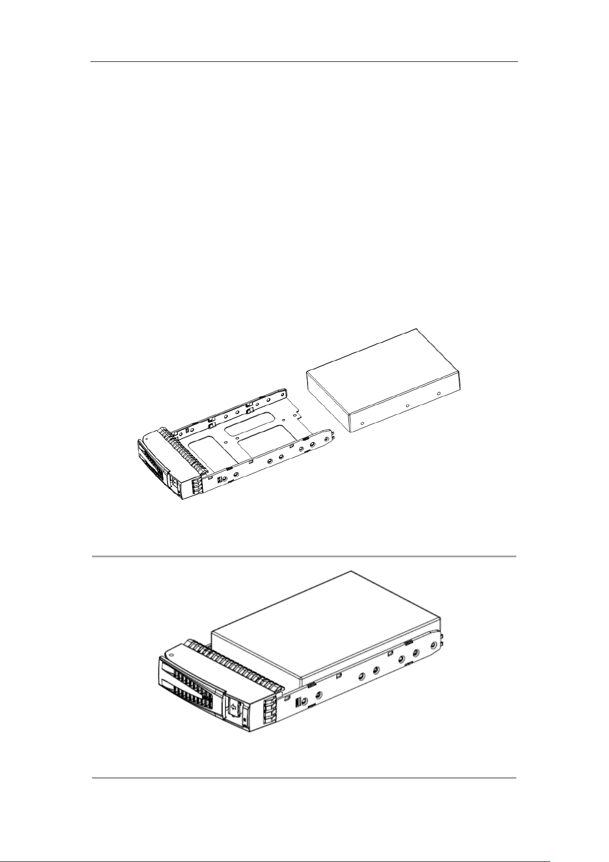
3. Use four screws to secure the HDD (with the PCB side downward) to the bracket. In order to
ensure the HDD pin holds the line with the rear of the plate, mount screws to the specific
screw hole as shown.
4. Insert the HDD bracket (with the PCB side towards the left of the chassis) to the chassis and
push it along the guide apparatus to the bottom. Then, press the securing handle to ensure
the bracket has been seated into position and lock it.
5. Repeat the operating steps above till all HDDs have been installed.
17
Figure 3-15 Split HDD Plate
Figure 3-16 HDD Installation Diagram

Quick Start Guide
3.4.2.3 Precautions during HDD Installation
When you plug or unplug the hard disks, please take the following precautions:
1. After you have plugged the hard disk to its mounting bracket, please use the provided screws
to fix the four edges of the mounting bracket.
2. Make sure the HDD mounting bracket is steadily plugged to the chassis along the slot.
3. When you unplug the hard disk, unplug it about 3cm away from the chassis and then make it
stay about 30 seconds on the slot guide before totally unplug it from the chassis. Since the
discs of the hard disk are still spinning at a high speed just after powering off, unplugging the
hard disk immediately will damage the discs.
4. The system supports disk hot swapping, yet the data storage safety is not ensured.
5. Please avoid frequent plugging/unplugging of the hard disks during the system running so as
to maintain long service life of the hard disks.
6. Take regular check and examine of the working status of the hard disks every two months, or
configure the system with auto check and examine task. Please refer to Chapter 4 for details.
7. The certification for the new hard disk is required when it is plugged to the system for the
first time. Please refer to Chapter 6 Creating and Managing Array for details.
Note: Please avoid unplugging a hard disk when it is writing/reading data so as to prevent data
loss.
3.4.3 Power on/off
Follow the steps below to power on/off properly.
Steps for Power on:
1. If the storage system is configured with redundant power supplies, please make all
connections of the power before starting the system.
2. Press the power switch on front panel to start the system. The system start-up will take
about 5 minutes.
If the unit fails to start up, please check whether all connections have been properly made.
As the unit has the power-off protection capability, the data will be automatically recovered
when it starts up again if the unit encounters power-off failure during its running.
Note: If the device connects a storage enclosure, please turn on the storage enclosure firstly and
then turn on the device.
Steps for Power off:
1. It is recommended to turn off the system by clicking the button under
the Maintanence > System Monitor interface in the storage system.
You can also reboot the system in the storage system.
18

Quick Start Guide
Notes:
In order to extend the device life, it is recommended to avoid to forcedly turn off the device
by using the POWER switch.
If the device connects a storage enclosure, please turn off the device firstly and then turn off
the storage enclosure.
19

Quick Start Guide
Chapter 4 Configuring Network Parameters
4.1 Login
You can use StorOS Manager or 4200 Client Software to configure network parameters. For
detailed information, please refer to corresponding user manuals. Management port and data
NIC 1 are also provided by the system to configure network parameters for each controller.
Before you start:
1. Configure the IP address of PC used to connect the storage system to the same network
segment with the manangement port (the default IP address for manage port is 10.254.254.254).
2. Use a crossover networking cable to connect the Ethernet port of you PC and the manage
port of the storage system.
3. Make sure the network communication between your PC and the storage system has been
established successfully.
Steps:
1. Input the IP address of the system in the WEB browser, e.g. https://10.254.254.254:2004, for
accessing to the homepage of the storage management system.
2. Input the user name web_admin and the default password 123 to login the system.
3. Click System > Network to enter network management interface.
In this interface you can configure network parameters. For details, refer to 4.2 Configuring
Network Parameters.
4. Steps above are suitable for connecting data NIC 1. The default IP address of network port 1
for controller A and controller B are 192.168.0.100 and 192.168.0.101 respectively.
4.2 Configuring Network Parameters
4.2.1 Editing Basic Network Paremeters
Steps:
1. Input IP address of the storage system in the WEB browser to login the system.
20

Quick Start Guide
Figure 4-1 Login
2. Click System > Network to enter network management interface.
3. Check the checkbox of NIC need to edit in the NIC information list.
4. Click the button to enter the following interface.
Figure 4-2 Modify NIC Info Interface
5. You can edit IP address, Subnet Mask, Gateway and MTU value in the interface.
Note: the settings will only take effect in the selected controller.
6. Click OK to save the settings.
4.2.2 Configuring Bonding Mode
If the controller has several NICs, it is highly recommended to configure bonding mode to keep
the reliability of data transmission.
Before you start:
Configure cluster management according to Chapter 5.5 Configuring Cluster Heartbeat.
Steps:
1. Click System > Network to network management interface.
2. Click the button of the Current NIC Bonding Mode.
3. Select the mode in the dropdown list.
4. Click OK to save the settings.
21

Quick Start Guide
Note: you need to reboot the system manually, so that the settings will take effect.
4.2.3 Configuring Multi-NIC Bonding
1. Click System > Network to network management interface.
2. Check the checkbox of NIC need to be bonded in the NIC Information list.
Figure 4-3 NIC Information interface
3. Click the button to pop up confirmation message box.
4. Click OK to save the settings. It takes a relatively short time to bond the NIC. And a message
box will pop up indicating that the bonding is created successfully. The bonded NIC will be
listed in the bond NIC info. IP address of the bond NIC is IP address of the data NIC 1.
Note: Please stop data accessing to the system during the bonding, or it may cause loss of data.
4.2.4 Deleting Multi-bonding Mode
1. Click System > Network to network management interface.
2. Check the checkbox of NIC need to release bonding in the bond NIC info list.
Figure 4-4 Bond NIC Info Interface
3. Click the button to pop up confirmation message box.
4. Click OK to release the bonding. It takes a relatively short time to delete bonding mode. And
a message box will pop up indicating that the bonding is released successfully.
Note: The building and deleting bonding operation will be synchronized to the two controllers.
22

Quick Start Guide
Manage PortManage Port
Controller A Controller B
Data NIC Data NIC
Client Server
Network Switch
4.2.5 Network Connecting Principle
It is recommended to obey following principles when connecting the storage system and the
client server to the network.
1. To keep stability of the network between the storage system and the client server, please
ensure they are in the same network segment.
2. Connect the client server and the two controllers to the same network switch.
3. Connect all the data NICs to the network switch.
Note: generally, the management port is used for debugging, not for linking. Data NIC also
provides debugging service.
23
Figure 4-5 Network Structure

Quick Start Guide
Chapter 5 Configuring CVR
5.1 Configuration Requirement
1. A private volume and a record volume should be established for realizing the function of
management and recording.
Note:
Private volume is mainly used to store recording index and database.
Record volume is used to store recording files.
Spare volume is used to keep the stability of the CVR. For it can take the place of the
private volume when an exception occurs to the private volume.
Archiving volume is also used to store recording files. The overwrite property can be
closed to protect the data in it and this is the difference between recording volume and
archiving volume.
2. For a large-scale project which big data is recorded, it is advised to create several record
volumes so that the load of recording from encoders will be shared. The space of a single
LUN volume forming the record volume is recommended to be less than 8T.
3. There is a certain proportion relationship between the size of private volume and record
volume. If the total size of all the record volume is larger than 60T, then the size of private
volume must be configured to 20G. If the total size of all the record volume is larger than
120T, then the size of private volume must be configured to 30G and so on.
4. Two ways are provided for configuration:
Option 1: quick-setting, you can refer to 5.4.1 Quick-setting for details.
Option 2: manual configuration, you can refer to 5.4.2 Manual configuration for details.
5.2 Configuring Cluster Heartbeat
Cluster system supports three functions: CVR, iSCSI and NAS. When a working controller is
something wrong, the work will be taken over by another controller to keep data safe. Besides,
the operation and configuration of one controller will be synchronized to another.
Establishing RAID and other settings of cluster storage system with two controllers are available,
only when cluster heartbeat is configured.
Before you start:
1. Ensure the communication of data NICs, which will be set to the cluster heartbeat NICs, in
the two controllers is normal.
2. Ensure no storage pool is added to the controllers. If there are storage pools in controllers,
you must reset the two controllers.
24

Quick Start Guide
Note: you can add storage pools after configuring cluster heartbeat is completed.
Auto configuration of cluster heartbeat is recommended.
Steps:
1. Auto configuration of controller A:
1) Input IP address of controller A in the WEB browser, e.g. https://(IP address of
controller A):2004.
2) Input the user name web_admin and the default password 123 to log in.
3) Click Cluster in the left bar to enter cluster management interface.
4) Click the button to pop up confirmation message box.
5) Click OK and wait for about 5 seconds. A message box of “Succeeded to configure
heartbeat automatically, please reboot system.” will pop up.
6) The heartbeat IP address of local cluster heartbeat and remote cluster heartbeat are
10.254.254.1 and 10.254.254.2 respectively. And subnet mask of heartbeat port is
10.254.254.248.
Figure 5-1 Cluster Management Interface of controller A
2. Auto configuration of controller B:
Steps:
1) Input IP address of controller B in the WEB browser, e.g. https://(IP address of
controller B):2004.
2) Repeat the 2)-5) of step 1 to set heartbeat.
3) The heartbeat IP address of local cluster heartbeat and remote cluster heartbeat are
10.254.254.2 and 10.254.254.1 respectively. And subnet mask of heartbeat port is
10.254.254.248.
25

Quick Start Guide
Figure 5-2 Cluster Management Interface of controller B
3. Click the button. The message box of “Testing cluster heartbeat
communication now, please check logs later.” will pop up.
If the log records “Cluster heartbeat communication is normal.”, indicating the
communication of the two controllers is normal.
If the log records “Cluster heartbeat communication is failed.”, you can reset the cluster
heatbeat or connect our service engineers.
4. Reboot the system when communication of the two controllers is normal. Follow step 3 to
check cluster heartbeat communication after the system restarts.
5.3 Configuring Resource IP Address
You can use resource IP in the client software to connect the system. Adding storage pool and
configuring CVR parameters are allowed.
Once the controller, which mounts the CVR service, is abnormal, the CVR service and resource IP
will mount to another controller. You can continue using the resource IP to connect CVR.
Following the steps below to configure resource IP address.
Steps:
1. Login one controller you want to configure.
2. Click Cluster in the left bar to enter cluster management interface.
3. Click the button to pop up the corresponding interface.
26

Quick Start Guide
Figure 5-3 Modify Resource IP Interface
4. Edit resource IP parameters.
1) Application: select application to CVR in the dropdown list.
2) Local resource network port:
Select the network port in the first option box to designate the network port for
which we modify the resource IP. Available network port are displayed in the
dropdown list(including bonding network port).
Select the resource virtual port in the second option box to designate the virtual
port of resource IP. It can be set to any integer ranges from 0 to 99.
3) Resource IP: Input an unoccupied and connectable IP address.
4) Netmask: Input an netmask the same to the netmask of network port.
5. Click OK to save the settings. An tips will pop up indicating whether the settings are
activated.
Note: resource IP can only be configured to one controller. The cluster device is shown as local in
controller which modified the resource IP and shown as remote in another controller. Besides,
resource IP can be only enabled in one controller.
27
Figure 5-4 Resource IP List

Quick Start Guide
Figure 5-5 Resource IP List
Notes:
CVR only support Active/Standby mode. And in this mode, CVR function runs on the main
controller.
CVR can only be operated while accessing by resource IP.
5.4 Configuring CVR
5.4.1 Quick Setting
If there is no storage pool and no RAID in the storage system, the quick-setting button in the CVR
management interface is activated.
Figure 5-6 CVR Management Interface
Click the button and click OK on the popup message box. Then the following
dialog box will show up.
28

Quick Start Guide
Figure 5-7 Process of Quick-setting
Follow the steps to configure CVR service, recording volume and archiving volume.
Steps:
1. Add the single HDD to the storage pool. Or establish the RAID and add the RAID to the
storage pool.
2. Establish a private volume, a spare volume and a record volume. An archiving volume is also
need to be established if there are more than 3 LUN volumes(except private volume and
archiving volume) in the system.
After quick-setting completed, you can view storage status in the storage pool interface. In
addtion, CVR service and LUN status are shown in the CVR management interface.
Figure 5-8 Storage Pool Status
29

Quick Start Guide
Figure 5-9 CVR Service and LUN Status
Notes:
Bad disk and alarm disk cannot be added to the storage pool.
It automatically turn into single disk mode, if any hard disk added is not an enterprise-level
hard disk.
It automatically turns into single disk mode, if disks in device are less than 6, no matter how
many disks in the storage enclosure. When the disks in device are not less than 6, if disks in
storage enclosure are less than 6, then the disk in storage enclosure will not be configured; if
disks in storage enclosure are not less than 6, then the disk in storage enclosure will be
added into RAID.
If the system has only one single disk, there is no need to create any spare volume. In the
single disk mode, the last disk in the system should not be created to spare volume. In the
RAID mode, two spare volumes should be created to each RAID.
The default size of private volume and spare volume created by qucik-setting is 50G.
5.4.2 Manual Configuration
Follow the steps below to configure private volume manually.
Steps:
1. Add the storage pool. Two ways are provided:
1) Single disk mode: Add the single HDD to the storage in order.
2) RAID mode: establish a RAID using these single HDDs. For details, you can refer to
Chapter 6.3 Storage Pool Management.
2. Assign the LUN volume.
1) Click Storage > LUN to enter LUN management interface.
2) Click the Create LUN button.
3) Input the LUN name, LUN size and Select the Block size.
30

Quick Start Guide
4) Click OK to save the LUN.
Notes: To configure private volume and its spare volume, at least 5 free LUNs should be
created and the size of at least 4 LUNs should no less than 20G. The rest LUNs will be used as
record volume.
Figure 5-10 Create LUN Interface
5) Click CVR > CVR to enter CVR management interface.
6) Click the button to enter CVR configuration interface.
7) Click the set private volume tab.
8) Select a free LUN in the Free LUN and click the button to set the
selected LUN as a private volume 1.
9) Select a free LUN in the Free LUN and click the button to set the
selected LUN as a private volume 2.
10) Check the checkbox of Start CVR after setting.
11) Click OK to save the settings.
31

Quick Start Guide
Figure 5-11 Set Private Volume Interface
Note: it is recommended to create LUNs of spare volume which is different from physical volume
of private volume. For detailed information about physical volume, please refer to 6.3 Storage
Pool Management.
3. Create the Record Volume.
1) Click CVR > CVR to enter CVR management interface.
2) Click the button to enter CVR configuration interface.
3) Click the Create record volume tab.
4) Input the Name and select the Data overlay and Usage in the dropdown list.
5) Select LUN source to LOCAL when the record volume is created in the local disk and
RAID. Or select the LUN source to IPSAN when the record volume is created in external
iSCSI disk.
6) Click OK to save the record volume.
32

Quick Start Guide
Figure 5-12 Create Record Volume Interface
5.5 Configuring Recording Schedules
5.5.1 Entering CVR Sub-system
Follow the two options below to enter CVR sub-system.
Option 1:
Steps:
1. Input CVR IP address in the WEB browser to enter login interface, e.g. https://resource IP
address:2004.
Figure 5-13 CVR Login Interface
2. Select the login system as CVR in the dropdown list.
3. Input the default user name nvr_admin and the default password 123.
4. Click Login to enter the system.
33

Quick Start Guide
Option 2:
Steps:
1. Login the storage system. For details, refer to the step 1 to 2 in 4.1 Login.
2. Click CVR > CVR to enter CVR management interface.
3. Click the button to enter CVR sub-system.
Figure 5-14 CVR Management Interface
4. Repeat step 1-4 in option 1 to log in CVR sub-system.
5.5.2 Adding Encoding Devices
Follow the steps below to add encoding devices.
Steps:
1. Enter CVR sub-system. For details, please refer to 5.5.1 Entering CVR Sub-system.
2. Click Device Management > Device.
3. Click the to pop up configuration interface.
Figure 5-15 Adding Encoding Device Interface
4. Input the parameters of the encoding device you want to add. You can input several
channels of one encoding device. E.g. input 1, 3-5, 7 in the channel means to add the 1, 3, 4,
5, 7 channel.
34

Quick Start Guide
5.5.3 Configuring Recording Schedules
Follow the steps below to configure recording schedules.
Steps:
1. Enter CVR sub-system. For details, please refer to 5.5.1 Entering CVR Sub-system.
2. Click Schedule & Alarm > Schedule to enter schedule configuration interface.
Figure 5-16 Make Plan Interface
3. Check the checkbox of Use encoding device or Use group in the left menu to assign the
encoder you want to make plan.
4. Check the checkbox of date need to configure.
5. Select record mode to Full-day or T ime 1-8 by checking the checkbox. If you choose the
time 1-8, you need to set detailed time.
6. Click OK to save the settings.
5.6 Reviewing Recording Function
5.6.1 Live View
Follow the steps below to start live view.
Steps:
1. Enter CVR sub-system. For details, please refer to 5.5.1 Entering CVR Sub-system.
2. Click Live View & Record > Device List.
3. Click to select encoding device you want to live view.
4. Click the button to start live view.
Note:
You need to add the IP address of encoding device to the trusted site before starting live
35

Quick Start Guide
view. Steps are shown below.
1) Click Tools > Internet Options in the IE browser and click the Security tab.
2) Click to select Trusted sites and click the button.
3) Input the IP address of the system in the zone and click the button.
4) Click Close to save the settings.
Figure 5-17 Adding Trusted Sites Interface
5) Click the button.
6) Set the status of ActiceX controls and plug-ins to Enable.
36

Quick Start Guide
Figure 5-18 Enable ActiveX Controls
5.6.2 Searching Recording Files
Follow the steps below to search recording files.
Steps:
1. Enter CVR sub-system. For details, please refer to 5.5.1 Entering CVR Sub-system.
2. Click Play & Download > Record Search.
3. Click the button.
Figure 5-19 Search Record Interface
4. Check the checkbox Use encoding device or Use group in the left menu to set the encoder
37

Quick Start Guide
you want to search recording files.
5. Set the search precondition in the right menu.
6. Click OK to start searching.
5.6.3 Playing Back Recording Files
Follow the steps below to play back recording files.
Steps:
1. Search recording files. For details, please refer to 5.6.2 Searching Recording Files.
2. Click to select recording files in the list.
3. Click the button to start playback.
38

Quick Start Guide
Chapter 6 Creating and Managing Array
The storage system provide redundant array for hard disk, namely RAID service. Especially RAID5
mode, it ensures no data loss.
Before using the system to store record data,you need to firstly add physical volume by adding
the disks or RAIDs to the virtual storage pool. And then create NAS and iSCSI by creating several
logic volume(LUN) in the added physical volume.
6.1 Disk Management
6.1.1 Disk Information
Follow the steps below to view disk information.
Steps:
1. Log in the storage system. For details, please refer to step 1-2 of 4.1 login.
2. Click Storage > Disk to enter disk management interface.
3. Click the button to scan all disks. And disks in the system will be listed in
the disk information.
Figure 6-1 Disk Information Interface
6.1.2 Checking Disk
The status for disk used for the first time is Unauthorize. You must check these disks before use.
Follow the steps below to check disks.
Steps:
1. Click Storage > Disk to enter disk management interface.
2. Check the checkbox of an unauthorized disk.
39

Quick Start Guide
Figure 6-2 Disk Information Interface
3. Click the button to enter disk check interface. The message box “Add disks to the
check queue!” will pop up.
4. Click Close in the message box. And The status of the disk displays as unsubmitted. In this
interface, there are three status about disk, they are Unsubmitted, Waiting and Checking.
Unsubmitted: the disk hasn’t been submitted to check.
Waiting: system is checking another disk. Until the checking finished, the waiting disk
will be checked.
Checking: the disk is being checked now.
Figure 6-3 Disk Checking Status
5. Click to select the check style for the disk. There two vaild options for check style: Quick
Check and Full Check.
Quick Check: a kind of parallel check for all the disk sections. It takes a short time.
Full Check: a kind of a serial check for all the disk sections. It takes a relatively long time.
And the check result is more accurate than Quick Check.
40

Quick Start Guide
6. Click the button to start checking. You can click the button to refresh
checking status.
7. Optionally, stop the disk check.
1) Click the button. The message box of “Do you want to stop the disk check?”
will pop up.
2) Click OK in the message box to stop the checking. You can refer to system log for the
current check result.
Note: It is recommended to set the period of disk check strategy to 3 months.
6.2 Array Management
6.2.1 Creating Array
Array is a data storage technology, which is created by several hard disks. It can improve the data
throughput of the system by storing and reading the data in multiple hard disks simutaneously.
The storage system provide 7 Array mode, like RAID0, RAID1, RAID3, RAID5, RAID6, RAID10 and
RAID50.
Follow the steps below to create array.
Steps:
1. Log in the storage system. For details, please refer to step 1-2 of 4.1 login.
2. Click Storage > Array to enter array management interface.
3. Click the button to enter the create array interface.
4. Input the Array name and choose the RAID level, Block size, I/O priority and Available disks
Array name: input numbers or letters in the text filed.
RAID level: you can select level to RAID0, RAID1, RAID3, RAID5, RAID6, RAID10 or
RAID50 in the dropdown list. In order to ensure the performance and stability of the
array, it is highly recommended to use disk with the same brand, model and size.
5. Click OK to save the array. The created array will be displayed in the array information list.
41

Quick Start Guide
Figure 6-4 Create Array Interface
6.2.2 Rebuilding Array
Rebuilding array function can save the data in a failure disk in a case that a disk in the array
becomes unsteady or breakdown. Besides, it can keep the integrity of the array. Before you
rebuild the array, please ensure there is at least a free disk in the system, which has the same size
with the failure disk.
6.2.2.1 Notice for Rebuilding
1. During the rebuilding, if the rebuilding disk lost or is pulled out, then the status of array will
be shown as degraded.
2. During the rebuilding, if an disk not for rebuilding lost, then the status of array will be shown
as disabled. And the status of disk for rebuilding will be shown as normal and the group will
be shown as free.
3. While the rebuilding disk occurs I/O fault, it is recommended to exchange the rebuilding
disk.
42

Quick Start Guide
6.2.2.2 Adding Hot Spare
Hot spare can automatically rebuild array. Once disk loss or disk failure happens to the array, the
hot spare disk will automatically replace the fault disk. Hot spares are advised to add when
creating array. And host spare mode includes Global mode and Local mode.
Follow the steps below to add hot spare for global mode and local mode.
Option 1: global mode
Steps:
1. Enter the array management interface
2. Click the button to enter add hot spare interface.
Figure 6-5 Add Hot Spare Interface
3. Click to select group to Global.
4. Check the checkbox of available disks.
5. Click OK to save the hot spare. And the added hot spare will be displayed in the hot spare
information.
Figure 6-6 Hot Spare Information Interface
43

Quick Start Guide
When an array lost a disk, the global hot spare will automatically rebuild the array.
Figure 6-7 Rebuild Array Interface
Option 2: local mode
Steps:
1. Repeat the step 1-2 for global mode
2. Click to select group to Local.
3. Select the array you want to add the hot spare to in the dropdown list.
4. Check the checkbox of available disks.
5. Click OK to add the hot spare. And the added hot spare will be displayed in the hot spare
information page.
Figure 6-8 Local Hot Spare
When the corresponding array degrades, the local hot spare will automatically rebuild the array.
6.2.2.3 Rebuilding Manually
When the array degrades, and no hot spare is configured. You can manually repair it.
Before you start:
Ensure there is at least one spare disk in the system.
Steps:
1. Click Storage > Array to enter array management interface.
2. Click the button to enter array maintanence interface.
44

Quick Start Guide
Figure 6-9 Array Information List
3. Click the button.
4. Check the checkbox of available disks.
5. Click OK to start rebuilding.
Figure 6-10 Array Maintanence Interface
Figure 6-11 Select Availiable Disk
45

Quick Start Guide
6.2.3 Checking and Repairing Array
Checking and repairing array can protect data in the storage system. Regular maintenance for
array can effectively lower the R/W error rate and increase the stability and integrity of the data.
6.2.3.1 Checking Array
Follow the steps below to check array manually.
Steps:
1. Click Storage > Array to enter array management interface.
2. Click the button in the array information list.
3. Click the button to start check.
Figure 6-12 Array Maintanence Interface
Figure 6-13 Array Information Interface
6.2.3.2 Adding Array Checking Strategy
Follow the steps to add new array checking strategies.
Before you start:
Make sure the status of array is normal, or strategies cannot be added.
Steps:
46

Quick Start Guide
1. Click Maintenance > Common to common maintenance interface.
2. Click the button to pop up add strategy interface.
Figure 6-14 Add Strategy Interface
3. Set the new strategy parameters.
1) Select Type to RAID verification in the dropdown list.
2) Check the checkbox of Check for Verify mode.
3) Set the Array name by checking the checkbox.
4) Input strategy Name, Cycle, Start time and End time.
4. Click OK to add the strategy. The new strategy will be shown in the RAID verify strategy info.
Figure 6-15 RAID verify strategy
6.2.3.3 Repairing Array
Two ways are provided to repair arrays: manual repair and strategic repair. Follow the steps
below to start repairing arrays.
47

Quick Start Guide
Option 1: Manual repair
Steps:
1. Click Storage > Array to enter array management interface.
2. Click the button in the array information list.
3. Click the button to start repairing.
Figure 6-16 Array Maintanence Interface
Figure 6-17 Array Information List
Option 1: strategy repairment
Before you start:
Make sure the status of array is normal, or strategies cannot be added.
Steps
1. Click Maintenance > Common to common maintenance interface.
2. Click the button to pop up add strategy interface.
48

Quick Start Guide
Figure 6-18 Add Strategy Interface
3. Set the new strategy parameters.
5) Select Type to RAID verification in the dropdown list.
6) Check the checkbox of Repair for Verify mode.
7) Set the Array name by checking the checkbox.
8) Input strategy Name, Cycle, Start time and End time.
4. Click OK to add the strategy. You can repair the array according to the new strategy.
6.3 Storage Pool Management
Virtual storage pool is a physical volume list. You can manage several disks and RAIDs by physical
volume. Physical volume can be divided into several volumes to provide different storage service.
6.3.1 Adding Storage Pool
If there is a normal disk or array in the system, you can follow the steps below to add storage
pool.
Steps:
1. Click Storage > Storage Pool to enter storage pool management interface.
2. Click the button to enter add storage pool interface.
49

Quick Start Guide
Figure 6-19 Add Storage Pool Interface
3. Check the checkbox of array in the Array information list.
4. Click OK to add the storage pool. And the added storage pool will be listed in the physical
volume information list.
Figure 6-20 Physical Volume Information List
You can create some free LUNs by dividing the physical volume of the array “array1”.
50

Quick Start Guide
Chapter 7 Configuring iSCSI
Configure iSCSI connection can map the space of storage system to the client server, so that to
manage the system locally.
7.1 Creating Array and Storage Pool
For details, please refer to Chapter 6 Creating and Managing Array.
7.2 Creating iSCSI Volume
Follow the steps below to create iSCSI Volume.
Steps:
1. Log in the storage system. For details, please refer to step 1-2 of 4.1 login.
2. Click Storage > LUN to enter logical volume management interface.
3. Click the button to enter create LUN interface.
Figure 7-1 Create LUN Interface
4. Input LUN name, LUN size in the text box and select the Block size, it is advised to set it to
4096Byte, in the dropdown list.
5. Click OK to save the LUN.
7.3 Enabling iSCSI
Follow the steps below to enable iSCSI
51

Quick Start Guide
Steps:
1. Click SAN > iSCSI to enter iSCSI management interface.
2. Click the button to enter enable iSCSI interface.
Figure 7-2 Enable iSCSI Interface
3. Input the Client IP, Local iSCSI ID and Remote iSCSI ID in the text box. Select CHAP
authentication and Access mode in the dropdown list. Check the checkbox of Availiable
LUN.
4. Click OK to save the settings.
7.4 Installing MPIO in Windows 2008
The framework of Microsoft(R) multipath I/O (MPIO) ensure data can be used at any time. MPIO
supports multiple data path of storage and improves the fault-tolerant of storage linkage. In some
situation, multi-path can provide more throughputs to improve the performance of the system.
When the 2008 server has installed the MPIO, then the MPIO will be shown in the start menu as
shown below.
52

Quick Start Guide
Figure 7-3 Start Menu
If the MPIO has not been installed, you can follow the steps below to install.
Steps:
1. Open the 2008 server and click Start > Administrative Tools > Server Manaer.
Figure 7-4 Start Menu
2. Click the Features button in the left navigation bar.
3. Click the button to pop up add features wizard interface.
53

Quick Start Guide
Figure 7-5 Server Manager Interface
4. Check the checkbox of Multipath I/0
5. Click the Next button.
54
Figure 7-6 Add Features Wizard Interface

Quick Start Guide
6. Click the button. The system will automatically install the multipath I/0.
Figure 7-7 Installation Confirmation Interface
Figure 7-8 Installation Succeeded Interface
7. After the installation completed, click Start > Administrator Tools > MPIO to enter MPIO
55

Quick Start Guide
properties interface and click the Discover Multi-paths tab. Then check the checkbox of add
support for iSCSI devices and click the Add button.
8. Reboot the server. And MPIO can be used normally after the server restarts.
7.5 Creating iSCSI Connection in Windows 2008
Follow the steps below to create iSCSI connection.
Steps:
1. Click Start > All Programs > Administrative Tools > iSCSI Initiator to enter iSCSI Initiator
properties interface.
Figure 7-9 iSCSI Initiator
2. Enter discover target portal interface.
Click the Discovery tab.
Click the discover Portal to pop up the discover target portal interface.
56

Quick Start Guide
Figure 7-10 Discover Target Portal Interface
3. Add two controllers of the storage system.
Input the IP address and iSCSI port of storage system in the IP address or DNS name
and Port respectively.
Click the OK to save the settings.
Repeat step 5-6 to add two controllers of the storage system.
57

Quick Start Guide
Figure 7-11 iSCSI Initiator Properties Interface
4. Connect to the targets.
Click the target tab.
Click to select a iSCSI target in the discovered targets and click the Connect button.
Optionally, check the checkbox of Add this connection to the list of Favorite Targets to
enable automatic connection to iSCSI storage system when the system restarts.
Click OK to save the settings.
58

Quick Start Guide
Figure 7-12 iSCSI Target Connection Interface
You can create several storage targets. The Inactive status indicates the target is discovered but
not been connected. The active status indicates the target is already connected. You can click the
Refresh to update the latest network information.
5. Configure the MPIO policy.
Right-click on the My Computer.
Click the Manage to enter server manager interface. And you can view the aggregated
iSCSI disks in the disk management interface.
Right-click on the disk and click Properties item.
Click the MPIO tab in the pop-up properties interface.
Select the MPIO policy to the Fail Over Only.
Note: in the fail over only, you need to configure an active path and others are standby
path. Select a path and click Edit button. Set the path state to standby and click OK.
Repeat the steps to other path to standby state until there is only one active path.
Click OK to save the settings.
59

Quick Start Guide
Figure 7-13 MPIO Policy Configuration Interface
60
Figure 7-14 Path State Configuration Interface

Quick Start Guide
After above configurations are completed, the iSCSI aggregates in the disk manager. You can use it
after formatting it.
6. Optionally, click to select the iSCSI target and click Disconnect button to disable connection
to the storage system.
7.6 Client Side Mapping/Formatting Local iSCSI
Disk
Follow the steps below to format local iSCSI disk.
Steps:
1. Configure the iSCSI connection. For details, you can refer to 8.5 Creating iSCSI Connection in
Windows 2008.
2. Enter the Disk Management interface to initialize and format the iSCSI disks. The iSCSI disk,
which is shown as new volume, is equipped with a driver. And the disk will be shown in the
My Computer window. You can visit the space provided by the storage system.
61
Figure 7-15 Disk Management Interface

Quick Start Guide
7.7 Establishing iSCSI Connection in Redhat 5
An operation sample in Red Hat Enterprise Linux 5.4(32bit) system is shown below.
Operations below lead you to connect linux server to the iSCSI storage system. Thus you can use
the storage system like a SCSI disk in the linux system.
1. Discover the target.
Establish iSCSI connection for each IP address of the double controller system. Following steps are
for two IP address, that is configure an IP address for each controller.
# iscsiadm -m discovery -t sendtargets -p 10.192.45.103:3260
10.192.45.103:3260,1 iqn.2004-05.storos.t-200
# iscsiadm -m discovery -t sendtargets -p 10.192.45.104:3260
10.192.45.104:3260,1 iqn.2004-05.storos.t-201
2. Log in the target.
# iscsiadm -m node -T iqn.2004-05.storos.t-200 -p 10.192.45.103:3260 -l
Login session [iface: default, target: iqn.2004-05.storos.t-200, portal: 10.192.45.103,3260]
# iscsiadm -m node -T iqn.2004-05.storos.t-201 -p 10.192.45.104:3260 -l
Login session [iface: default, target: iqn.2004-05.storos.t-201, portal: 10.192.45.104,3260]
3. Review Disk Information.
# fdisk –l
Disk /dev/sda: 8589 MB, 8589934592 bytes
255 heads, 63 sectors/track, 1044 cylinders
Units = cylinders of 16065 * 512 = 8225280 bytes
Device Boot Start End Blocks Id System
/dev/sda1 * 1 13 104391 83 Linux
/dev/sda2 14 128 923737+ 82 Linux swap / Solaris
/dev/sda3 129 1043 7349737+ 83 Linux
/dev/sda4 1044 1044 8032+ 5 Extended
/dev/sda5 1044 1044 8001 8e Linux LVM
Disk /dev/sdb: 10.4 GB, 10468982784 bytes
64 heads, 32 sectors/track, 9984 cylinders
Units = cylinders of 2048 * 512 = 1048576 bytes
Disk /dev/sdb doesn't contain a valid partition table
Disk /dev/sdc: 10.4 GB, 10468982784 bytes
64 heads, 32 sectors/track, 9984 cylinders
Units = cylinders of 2048 * 512 = 1048576 bytes
Disk /dev/sdc doesn't contain a valid partition table
62

Quick Start Guide
As shown above, after connecting and logging in the target of double controller, you can input
fdisk –l to view the extra external iSCSI disk.
4. Configure multipath aggregated iSCSI disk.
1) Configure multipath for Redhat server to aggregate multipath. Please contact service
center for confituration files and confituration method.
2) Input aggregation command.: multipath -v2.
3) View the dm information of aggregation.
Input multipath –ll to view the dm information of aggergation. An example is shown
below:
4816549b28b9BNiSCSI_1dm-0 BN ,SCST_BRAINAIRE
[size=78G][features=0][hwhandler=0]
\_ round-robin 0 [prio=1][enabled]
\_ 4:0:0:0 sde 8:64 [active][ready]
\_ round-robin 0 [prio=1][active]
\_ 3:0:0:0 sdd 8:48 [active][ready]
5. Format the disk partition.
fdisk /dev/dm-0
Information are shown below after configuring an partition:
fdisk –l
Disk /dev/dm-0: 83.8 GB, 83886080000 bytes
255 heads, 63 sectors/track, 10198 cylinders
Units = cylinders of 16065 * 512 = 8225280 bytes
Device Boot Start End Blocks Id System
/dev/dm-0p1 1 10198 81915403+ 83 Linux
Please reboot the client server after partitioning the iSCSI disk.
6. Formate file system.
Firstly, view the partition status: ll /dev/mapper/*
If partition exists, then formate file system: mkfs.ext3 /dev/mapper/---p1
7. Mounting
# mkdir -p /mnt/iscsi1
# mount /dev/mapper/--p1 /mnt/iscsi1
If you need to configure automatic connection for iSCSI disk after rebooting linux server, add
mounting command to the /etc/rc.local file:
vi /etc/rc.local
# Add mount in the end of the file
mount /dev/mapper/--p1 /mnt/iscsi1
63

Quick Start Guide
Chapter 8 Managing Failure Disk
The disks are more likely to breakdown with the service time increasing. And that is why we
create RAID5 mode. RAID5 mode can continue to run even though a disk failed, but you should
exchange the fault disk as soon as you can to avoid data loss and performance degradation.
8.1 Disk Alarm
Follow the steps below to view disk alarm.
Steps:
1. Log in the storage system. For details, please refer to step 1-2 of 4.1 login.
2. Click Storage > Disk to view disk state.
Figure 9. 1 Disk Management Interface
The system will automatically detect disk if the status of disk is abnormal. After the
detection, the alarm info window will alarm timely for the failure disks and the detailed
detection information, including location and model, will be listed.
Figure 8-1 Alarm Info Interface
8.2 Exchanging Failure Disks
Follow the steps to exchanging failure disks.
Steps:
1. Pull out the failure disk.
64

Quick Start Guide
2. Input the new disk into the former disk slot.
3. Check the new disk. For details, you can refer to 7.1.2 Checking Disk.
4. Rebuild the new disk to the former array. For details, you can refer to 7.2.2 Rebuilding Array.
5. Continually using the failure may result in losing data. You can send the failure disk to the
disk manufacturer or the storage system manufacturer for further detection.
65

Quick Start Guide
Chapter 9 Notes
1) IE6, IE7, IE8 and IE9 browser are supported by the storage system.
2) The default IP address of data NIC for cluster controller A and B is 192.168.0.100 and
192.168.0.101 respectively. And the default bonding mode is active-backup.
3) If you forget the edited IP address of the data NIC, you can use a networking cable to
connect your PC and the management port of the storage system. And set the IP address of
PC to 10.254.254.xxx. Then you can visit the https://10.254.254.254:2004 with you PC to
confirm the IP address of the data NIC.
Another way is to connect hyperterminal by COM1 serial port(set the baud rate to 115200)
and input the ifconfig command to get the IP address.
4) You may enter the storage system by visiting https://10.254.254.254:2004, with the use
name web_admin and default password 123.
5) The storage management system interface may disconnected after editing the IP address of
data NIC. Please input the new data NIC IP address to login the storage system
66

Quick Start Guide
Parts Name
Regulated Substances and Elements in “Testing Methods for Regulated Substances
in Electronic Information”
Lead(Pb)
Mercury
(Hg)
Cadmium
(Cd)
Hexavalent
Chromium
(CrⅥ)
Polybrominated
Biphenyls
(PBB)
Polybrominated
Diphenyl Ethers
(PBDE)
Metal Parts
× Ο Ο Ο Ο
Ο
Circuit Board
× Ο Ο Ο Ο Ο Plastic Parts(if any)
Ο Ο Ο Ο Ο
Ο
Display Board(if any)
× Ο Ο Ο Ο
Ο
Power Supply(if any)
× Ο Ο Ο Ο Ο Controller(if any)
× Ο Ο Ο Ο
Ο
Attachment(if any)
× Ο Ο Ο Ο
Ο
Note:
Ο represents the content of regulated substance in the part is within the SJ/T 11363-2006 standard.
× represents the content of regulated substance in the part is out of the SJ/T 11363-2006 standard.
Identifier list of Regulated Substances
and Elements
67

Quick Start Guide
Date
Fault Description
Detailed Information of Maintanence and
Serial No. Changing
Warranty Card A
User Name:
Address:
Telephone: Fax No.: ZIP Code:
E-mail:
Product Model:
Serial No.(S/N):
Production Date: Year Month Day
Purchasing Date: Year Month Day
Warranty Period: Months
If you have any requirements, please fill in below:
Dealer: Telephone:
Distribution Unit:(Seal)
Maintenances Record:
Note: If products are exchanged, please record the primary serial No..
This receipt is for dealer to keep.
68

Quick Start Guide
Warranty Service
Thank you for choosing our products, please fill in the warranty card and send the warranty card B back to
the manufacturer. The manufacturer will register and record you information, so to protect you rights and
interests below:
1. With the warranty card, you can enjoy free maintenance in warranty period and preferential service
after warranty period. The warranty period is one year since purchasing day.
2. Within 7 days after purchasing day, you can enjoy free replacement if product is something wrong.
3. You can be firstly informed of our new products information and preferential activities.
4. Users, who have completed the register, have the chance to attend training and other activities hold
unregularly.
User Name:
Product Model:
Serial No.(S/N):
Production Date: Year Month Day
Purchasing Date: Year Month Day
Dealer:
Telephone: Fax No.: ZIP Code:
E-mail:
Distribution Unit:(Seal)
This receipt is for user to keep.
Notes:
1. We will not provide warranty for faults caused by following situations:
Faults caused by accident, negligence, disaster, misoperation.
Faults caused by improper working environment or requirement. E.g. unsuitable
power supply, inappropriate temperature and humidity.
Products maintenance by organisation without authorization from manufacturer.
Products have been sold over 12 months.
2. Please contact dealers or service agencies, with the register card, for technical service.
3. If you have any objections about technical service provided by dealer, you can complain
to the manufacturer technical service center.
4. Warranty card is effective only when it has been sealed by warranty unit.
69

Quick Start Guide
User Name:
Address:
Telephone: Fax No.: ZIP Code:
E-mail:
Produce Model:
Serial No.(S/N):
Production Date: Year Month Day
Purchasing Date: Year Month Day
Warranty Period: Months
If products are exchanged, please fill primary production date: Year
Month Day
Primary Serial No.(S/N):
If you have any requirements, please fill in below:
Dealer: Telephone:
Distribution Unit:(seal)
Mailing Address:
ZIP Code:
Note: Please send the receipt back to the manufacturer, or manufacturer will not provide
after-sales service for you.
Warranty Card B
70
 Loading...