

Hikvision DS-7308HQI-K4-10TB, DS-7308HQI-K4-12TB, DS-7308HQI-K4-16TB, DS-7308HQI-K4-18TB, DS-7308HQI-K4-1TB User Manual
...
User Manual
Digital Video Recorder (DVR)
DS-73xxHUI-K4, DS-73xxHQI-K4, DS-90xxHUI-K8
UM DS-73xxHUI-K4 DS-73xxHQI-K4 DS-90xxHUI-K8 092017NA i

Manual Illustrations and Features
Graphics (screen shots, product pictures, etc.) in this document are for illustrative purposes only. Your
actual product may differ in appearance. Your product might not support all features discussed in this
document.
Hikvision USA Inc., 18639 Railroad St., City of Industry, CA 91748, USA • Hikvision Canada, 4848 rue
Levy, Saint Laurent, Quebec, Canada, H4R 2P1
Telephone: +1-909-895-0400 • Toll Free in USA: +1-866-200-6690 • E-Mail: sales.usa@hikvision.com •
www.hikvision.com
COPYRIGHT ©2017-2018 Hangzhou Hikvision Digital Technology Co., Ltd.
ALL RIGHTS RESERVED.
Any and all information, including, among others, wordings, pictures, graphs are the properties of
Hangzhou Hikvision Digital Technology Co., Ltd. or its subsidiaries (hereinafter referred to be
“Hikvision”). This user manual (hereinafter referred to be “the Manual”) cannot be reproduced,
changed, translated, or distributed, partially or wholly, by any means, without the prior written
permission of Hikvision. Unless otherwise stipulated, Hikvision does not make any warranties,
guarantees or representations, express or implied, regarding to the Manual.
About this Manual
This Manual is applicable to Turbo HD Digital Video Recorder (DVR).
The Manual includes instructions for using and managing the product. Pictures, charts, images and all
other information hereinafter are for description and explanation only. The information contained in
the Manual is subject to change, without notice, due to firmware updates or other reasons. Please find
the latest version in the company website (http://overseas.hikvision.com/en/).
lease use this user manual under the guidance of professionals.
P
Trademarks Acknowledgement
and other Hikvision trademarks and logos are the properties of Hikvision in various
jurisdictions. Other trademarks and logos mentioned below are the properties of their respective
owners.
Legal Disclaimer
TO THE MAXIMUM EXTENT PERMITTED BY APPLICABLE LAW, THE PRODUCT DESCRIBED, WITH ITS
HARDWARE, SOFTWARE AND FIRMWARE, IS PROVIDED “AS IS”, WITH ALL FAULTS AND ERRORS, AND
HIKVISION MAKES NO WARRANTIES, EXPRESS OR IMPLIED, INCLUDING WITHOUT LIMITATION,
MERCHANTABILITY, SATISFACTORY QUALITY, FITNESS FOR A PARTICULAR PURPOSE, AND
NON-INFRINGEMENT OF THIRD PARTY. IN NO EVENT WILL HIKVISION, ITS DIRECTORS, OFFICERS,
EMPLOYEES, OR AGENTS BE LIABLE TO YOU FOR ANY SPECIAL, CONSEQUENTIAL, INCIDENTAL, OR
INDIRECT DAMAGES, INCLUDING, AMONG OTHERS, DAMAGES FOR LOSS OF BUSINESS PROFITS,
BUSINESS INTERRUPTION, OR LOSS OF DATA OR DOCUMENTATION, IN CONNECTION WITH THE USE OF
THIS PRODUCT, EVEN IF HIKVISION HAS BEEN ADVISED OF THE POSSIBILITY OF SUCH DAMAGES.
REGARDING TO THE PRODUCT WITH INTERNET ACCESS, THE USE OF PRODUCT SHALL BE WHOLLY AT
YOUR OWN RISKS. HIKVISION SHALL NOT TAKE ANY RESPONSIBILITES FOR ABNORMAL OPERATION,
PRIVACY LEAKAGE OR OTHER DAMAGES RESULTING FROM CYBER ATTACK, HACKER ATTACK, VIRUS
UM DS-73xxHUI-K4 DS-73xxHQI-K4 DS-90xxHUI-K8 092017NA 2
DS-73xxHUI-K4, DS-73xxHQI-K4, DS-90xxHUI-K8 DVR User Manual
INSPECTION, OR OTHER INTERNET SECURITY RISKS; HOWEVER, HIKVISION WILL PROVIDE TIMELY
TECHNICAL SUPPORT IF REQUIRED.
SURVEILLANCE LAWS VARY BY JURISDICTION. PLEASE CHECK ALL RELEVANT LAWS IN YOUR
JURISDICTION BEFORE USING THIS PRODUCT IN ORDER TO ENSURE THAT YOUR USE CONFORMS THE
APPLICABLE LAW. HIKVISION SHALL NOT BE LIABLE IN THE EVENT THAT THIS PRODUCT IS USED WITH
ILLEGITIMATE PURPOSES.
IN THE EVENT OF ANY CONFLICTS BETWEEN THIS MANUAL AND THE APPLICABLE LAW, THE LATER
PREVAILS.
Regulatory Information
FCC Information
Please take attention that changes or modification not expressly approved by the party responsible for
compliance could void the user’s authority to operate the equipment.
FCC compliance: This equipment has been tested and found to comply with the limits for a Class A
digital device, pursuant to part 15 of the FCC Rules. These limits are designed to provide reasonable
protection against harmful interference when the equipment is operated in a commercial environment.
This equipment generates, uses, and can radiate radio frequency energy and, if not installed and used
in accordance with the instruction manual, may cause harmful interference to radio communications.
Operation of this equipment in a residential area is likely to cause harmful interference in which case
the user will be required to correct the interference at his own expense.
FCC Conditions
This device complies with part 15 of the FCC Rules. Operation is subject to the following two conditions:
1. This device may not cause harmful interference.
2. This device must accept any interference received, including interference that may cause undesired
operation.
EU Conformity Statement
This product and - if applicable - the supplied accessories too are marked with "CE" and
comply therefore with the applicable harmonized European standards listed under the EMC
Directive 2014/30/EU, the LVD Directive 2014/35/EU, the RoHS Directive 2011/65/EU.
2012/19/EU (WEEE directive): Products marked with this symbol cannot be disposed of as
unsorted municipal waste in the European Union. For proper recycling, return this product to
your local supplier upon the purchase of equivalent new equipment, or dispose of it at
designated collection points. For more information see: www.recyclethis.info
2006/66/EC (battery directive): This product contains a battery that cannot be disposed of as
unsorted municipal waste in the European Union. See the product documentation for specific
battery information. The battery is marked with this symbol, which may include lettering to
indicate cadmium (Cd), lead (Pb), or mercury (Hg). For proper recycling, return the battery to
your supplier or to a designated collection point. For more information see: www.recyclethis.info
Industry Canada ICES-003 Compliance
This device meets the CAN ICES-3 (A)/NMB-3(A) standa
UM DS-73xxHUI-K4 DS-73xxHQI-K4 DS-90xxHUI-K8 032918NA 3
rds requirements.
DS-73xxHUI-K4, DS-73xxHQI-K4, DS-90xxHUI-K8 DVR User Manual
Applicable Models
This manual is applicable to the models listed in the following table.
Series Model
DS-7304HUI-K4
DS-73xxHUI-K4
DS-7308HUI-K4
DS-7316HUI-K4
DS-7332HUI-K4
DS-7308HQI-K4
DS-73xxHQI-K4
DS-7316HQI-K4
DS-7332HQI-K4
DS-9008HUI-K8
DS-90xxHUI-K8
DS-9016HUI-K8
DS-9032HUI-K8
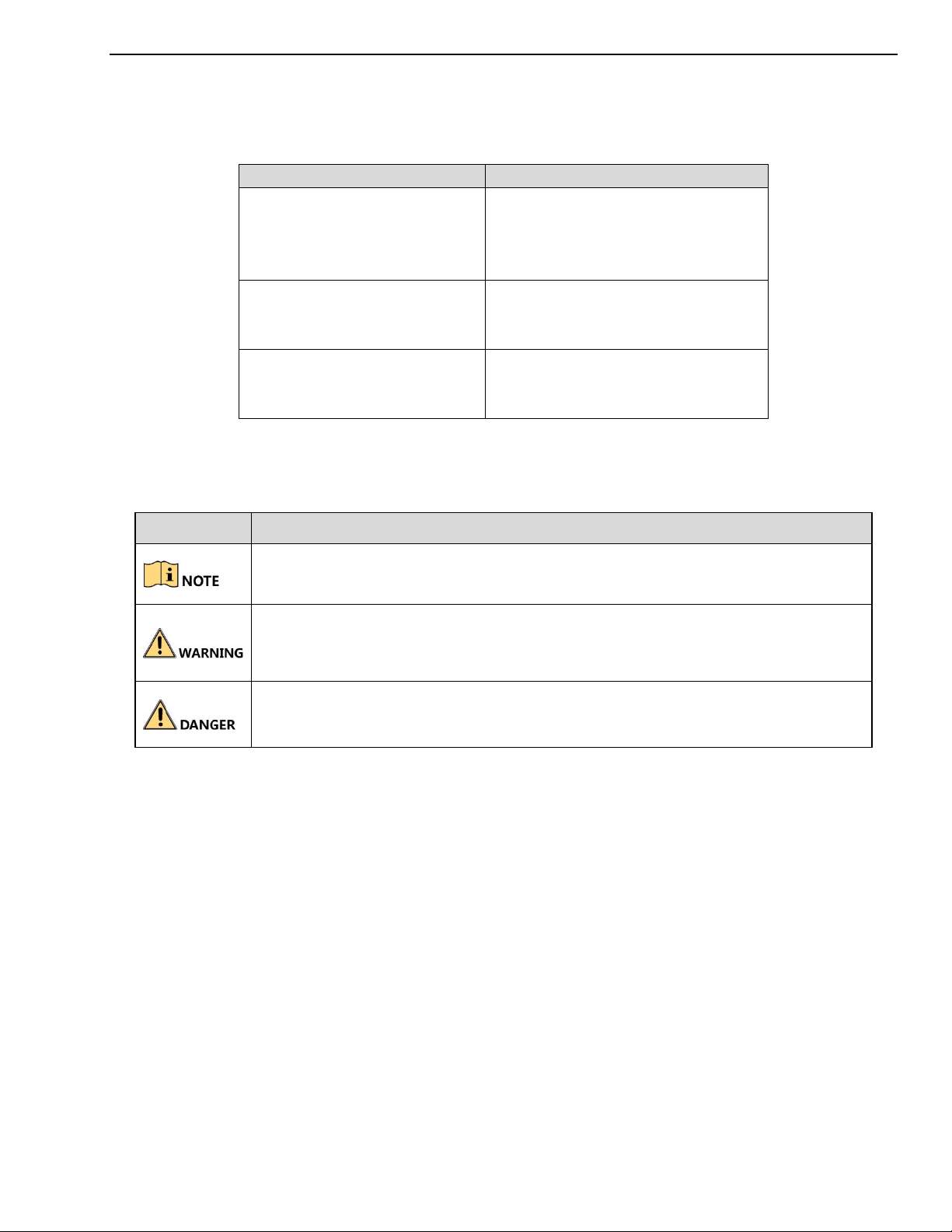
Symbol Conventions
The symbols that may be found in this document are defined as follows.
Symbol Description
Provides additional information to emphasize or supplement important points
of the main text.
Indicates a potentially hazardous situation, which if not avoided, could result in
equipment damage, data loss, performance degradation, or unexpected results.
Indicates a hazard with a high level of risk, which if not avoided, will result in
death or serious injury.
Mandatory Electrical Requirements
Hikvision requires the following conditions and equipment for all of its electronic equipment:
• Grounding
Ensure good conductivity for all ground paths; examine ground path contact surfaces for defects,
dirt, corrosion, or non-conductive coatings that may impede conductivity. Repair or clean contact
surfaces as necessary to assure good metal-to-metal contact. Ensure fasteners are properly
installed and tightened.
• Electrical Wiring
Ensure your outlets are properly wired. They can be checked with an electrical outlet tester.
• Surge Suppressor (Required)
Hikvision is not responsible for any damage to equipment caused by power spikes in the electrical
power grid. Use of a surge suppressor meeting the following specifications is mandatory for all
Hikvision electronic equipment:
UM DS-73xxHUI-K4 DS-73xxHQI-K4 DS-90xxHUI-K8 032918NA 4

DS-73xxHUI-K4, DS-73xxHQI-K4, DS-90xxHUI-K8 DVR User Manual
•
Specifications
˗ Listed by Underwriter’s Laboratories, meeting the UL 1449 Voltage Protection Rating (VPR)
˗ Minimum protection of 1,000 joules or higher
˗ Clamping voltage of 400 V or less
˗ Response time of 1 nanosecond or less
• Usage
˗ Surge suppressors must not be daisy chained with pow
• Maintenance
er strips or other surge suppressors
˗ Replace after a serious electrical event (e.g., lighting blew out a transformer down the street)
˗ Replace yearly in storm-prone areas
˗ Replace every two years as routine maintenance
Safety Instructions
• Proper configuration of all passwords and other security settings is the responsibility of the
installer and/or end-user.
• In the use of the product, you must be in strict compliance with the electrical safety regulations of
the nation and region. Please refer to technical specifications for detailed information.
• Input voltage should meet both the SELV (Safety Extra Low Voltage) and the Limited Power Source
with 100 to 240 VAC, 12 VDC or 48 VDC according to the IEC60950-1 standard. Refer to technical
specifications for detailed information.
• Do not connect several devices to one power adapter as adapter overload may cause over-heating
or a fire hazard.
• Please make sure that the plug is firmly connected to the power socket.
• If smoke, odor or noise rise from the device, turn off the power at once and unplug the power
cable, and then please contact the service center.
Preventive and Cautionary Tips
Before connecting and operating your device, please be advised of the following tips:
• Ensure unit is installed in a well-ventilated, dust-free environment.
• Unit is designed for indoor use only.
• Keep all liquids away from the device.
• Ensure environmental conditions meet factory specifications.
• Ensure unit is properly secured to a rack or shelf. Major shocks or jolts to the unit as a result of
dropping it may cause damage to the sensitive electronics within the unit.
• Use the device in conjunction with an UPS if possible.
• Power down the unit before connecting and disconnecting accessories and peripherals.
• A factory recommended HDD should be used for this device.
UM DS-73xxHUI-K4 DS-73xxHQI-K4 DS-90xxHUI-K8 032918NA 5

DS-73xxHUI-K4, DS-73xxHQI-K4, DS-90xxHUI-K8 DVR User Manual
• Improper use or replacement of the battery may result in hazard of explosion. Replace with the
same or equivalent type only. Dispose of used batteries according to the instructions provided by
the battery manufacturer.
• Ensure to use the attached power adaptor only and not to change the adaptor randomly.
Product Key Features
General
• Connectable to TurboHD and analog cameras
• Supports UTC protocol for connecting camera over coax
• Connectable to IP cameras
• The analog signal inputs including TurboHD and CVBS can be automatically recognized without
configuration
• Each channel supports dual-stream. And sub-stream supports up to WD1 resolution
• The main stream of HUI Series supports up to 5 MP resolution of all the channels (HUI Series)
• 5 MP long distance transmission can be enabled for the analog cameras (HUI Series)
• Independent configuration for each channel, including resolution, frame rate, bit rate, image
quality, etc.
• The minimum frame rate for main stream and sub-stream is 1 fps
• Encoding for both video stream and video & audio stream; audio and video synchronization during
composite stream encoding
• Supports enabling H.265+/H.264+ to ensure high video
• H.265+/H.265/H.264+/H.264 encoding for the main stream, and H.265/H.264 encoding for the
sub-stream of analog cameras
• Connectable to H.265 and H.264 IP cameras
• Defog level, night to day sensitivity, day to night sensitivity, IR light brightness, day/night mode, and
WDR switch configurable for the connected analog cameras supporting these parameters
• 4 MP/5 MP signal switch for the supported analog cameras
• Watermark technology
Local Monitoring
• HDMI output at up to 4K (3840 × 2160) resolution
quality with lowered bit rate
• There are two HDMI interfaces of which the HDMI1 and VGA interfaces share simultaneous output.
For HDMI1/VGA output, up to 1920 × 1080 resolution is supported. For HDMI2 output, up to 4K
(3840 × 2160) resolution is supported
• 1/4/6/8/9/16/25/36 screen live view is supported, an
d the display sequence of screens is adjustable
If the sum of the analog and IP channels exceeds 25, up to 32-window division mode is
supported for the VGA/HDMI1 output
UM DS-73xxHUI-K4 DS-73xxHQI-K4 DS-90xxHUI-K8 032918NA 6

DS-73xxHUI-K4, DS-73xxHQI-K4, DS-90xxHUI-K8 DVR User Manual
• Live view screen can be switched in group and manual switch and automatic cycle live view are also
provided, the interval of automatic cycle can be adjusted
• CVBS output only serves as the aux output or live view output
• Quick setting menu is provided for live view
• The selected live view channel can be shielded
• VCA information overlay in live view for the supported analog cameras and in smart playback for
the supported analog and IP cameras
• Motion detection, video-tampering detection, video e
xception alarm, video loss alarm, and VCA
alarm functions
• 1-ch analog camera supports people counting and heat map functions
• HUI Series supports line crossing detection and intrusion detection of all channels, and 2-ch sudden
scene change detection.
• The enhanced VCA mode conflicts with the 2K/4K output and 4 MP/5 MP signal input (HUI Series)
• Privacy mask
• Several PTZ protocols (including Omnicast VMS of Genetec) supported; PTZ preset, patrol and
pattern
• Zooming in/out by clicking the mouse and PTZ tracing by dragging mouse.
HDD Management
• Each disk can have a maximum of 8 TB storage capacity
• 8 network disks (8 NAS disks, 8 IP SAN disks, or n N
AS disks + m IP SAN disks (n+m ≤ 8)) can be
connected
• Remaining recording time of the HDD can be viewed
• Supports cloud storage
• S.M.A.R.T. and bad sector detection
• HDD sleeping function
• HDD property: redundancy, read-only, read/write (R/W)
• HDD group management
• HDD quota management; different capacity can be assigned to different channels
• Hot-swappable HDD supports RAID 0, RAID 1, RAID 5, RAID 6, and RAID 10 storage schemes, and
can be enabled and disabled on your demand. 16 arrays can be configured (DS-90xxHUI-K8 only)
Recording, Capture, and Playback
• Holiday recording schedule configuration
• Cycle and non-cycle recording modes
• Normal and event video encoding parameters
• Multiple recording types: manual, continuous, alarm,
motion, motion | alarm, motion & alarm, and
event
UM DS-73xxHUI-K4 DS-73xxHQI-K4 DS-90xxHUI-K8 032918NA 7

DS-73xxHUI-K4, DS-73xxHQI-K4, DS-90xxHUI-K8 DVR User Manual
• Supports POS triggered recording
• Eight recording time periods with separated recording types
• Supports Channel-Zero encoding
• Main stream and sub-stream configurable for simultaneous recording
• Pre-record and post-record for motion detection triggered recording, and pre-record time for
schedule and manual recording
• Searching record files and captured pictures by even
ts (alarm input/motion detection)
• Customization of tags, searching and playing back by tags
• Locking and unlocking of record files
• Local redundant recording and capture
• When TurboHD input is connected, the information including the resolution and frame rate will be
overlaid on the bottom right corner of the live view for five seconds. When CVBS input is
connected, the information such as NTSC or PAL will be overlaid on the bottom right corner of the
live view for five seconds.
• Search and play back record files by camera number, recording type, start time, end time, etc.
• Smart playback to go through less effective information
• Main stream and sub-stream selectable for local/remote playback
• Zooming in for any area when playback
• Multi-channel reverse playback
• Supports pause, fast forward, slow forward, skip forward, and skip backward when playback,
locating by dragging the mouse on the progress bar
• 4/8/16-ch synchronous playback
• Manual capture, continuous capture of video images,
and playback of captured pictures
Backup
• Exports data to a USB or eSATA device
• Exports video clips when playback
• Video and Log, Video and Player, and Player are selectable to export for backup
• Management and maintenance of backup devices
Alarms and Exceptions
• Configurable arming time of alarm input/output
• Alarms for video loss, motion detection, video tampering, illegal login, network disconnected, IP
confliction, record/capture exception, HDD error, and HDD full, etc.
• Alarm triggers full screen monitoring, audio alarm,
notifying surveillance center, sending email and
alarm output
• One-key disarms the linkage actions of the alarm input
• PTZ linking for the VCA alarm
UM DS-73xxHUI-K4 DS-73xxHQI-K4 DS-90xxHUI-K8 032918NA 8

DS-73xxHUI-K4, DS-73xxHQI-K4, DS-90xxHUI-K8 DVR User Manual
• VCA detection alarm is supported
• Supports POS triggered alarm
• Supports coaxial alarm (requires camera with alarm I/O)
• System will automatically reboot when a problem is detected in an attempt to restore normal
functionality
Other Local Functions
• Manual and automatic video quality diagnostics
• Operable by mouse and remote control
• Three-level user management; admin user can create m
any operating account and define their
operating permission, which includes the permission to access any channel
• Completeness of operation, alarm, exceptions and log writing and searching
• Manually triggering and clearing alarms
• Importing and exporting of configuration file of devices
• Getting cameras type information automatically
• Unlock pattern for device login for the admin
• Clear-text password available
• GUID file can be exported for use in resetting the password
• Multiple connected analog cameras supporting TurboHD can be upgraded simultaneously via the
DVR
Network Functions
• Self-adaptive 100M or 1000M network interface
• IPv6 is supported
• TCP/IP protocol, PPPoE, DHCP, DNS, DDNS, NTP, SADP,
SMTP, NFS, iSCSI, UPnP™, and HTTPS are
supported
• Supports access by Hik-Connect. If you enable Hik-Connect, the device will remind you the Internet
access risk and ask you to confirm the “Terms of Service” and “Privacy Statement” before enabling
the service. You should create a verification code to connect to Hik-Connect.
• TCP, UDP, and RTP for unicast
• Auto/Manual port mapping by UPnP™
• Remote search, playback, download, locking and unlocking the record files, and downloading files
broken transfer resume
• Remote parameters setup; remote import/export of device parameters
• Remote viewing of the device status, system logs and
alarm status
• Remote keyboard operation
• Remote HDD formatting and program upgrading
• Remote system restart and shutdown
UM DS-73xxHUI-K4 DS-73xxHQI-K4 DS-90xxHUI-K8 032918NA 9

DS-73xxHUI-K4, DS-73xxHQI-K4, DS-90xxHUI-K8 DVR User Manual
• Supports upgrading via remote FTP server
• RS-485 transparent channel transmission
• Alarm and exception information can be sent to the remote host
• Remotely start/stop recording
• Remotely start/stop alarm output
• Remote PTZ control
• Two-way audio and voice broadcasting
• Output bandwidth limit configurable
• Embedded Web server
• If DHCP is enabled, you can enable DNS DHCP or disab
le it and edit the Preferred DNS Server and
Alternate DNS Server
Development Scalability
• SDK for Windows and Linux system
• Source code of application software for demo
• Development support and training for application system
UM DS-73xxHUI-K4 DS-73xxHQI-K4 DS-90xxHUI-K8 032918NA 10

DS-73xxHUI-K4, DS-73xxHQI-K4, DS-90xxHUI-K8 DVR User Manual
Table of Contents
Product Key Features ............................................................................................................... 6
NOTE: Figures in this manual are for illustration only; your screens may differ. ...................... 16
1 Introduction .................................................................................................................................. 16
1.1 Front Panel .................................................................................................................................... 16
1.2 IR Remote Control Operations .................................................................................................. 18
1.2.1 Troubleshooting Remote Control ........................................................................................ 20
1.3 USB Mouse Operation ................................................................................................................ 20
1.4 Input Method Description .......................................................................................................... 21
1.5 Rear Panel ..................................................................................................................................... 21
2 Getting Started ............................................................................................................................. 23
2.1 Starting Up and Shutting Down the DVR ............................................................................... 23
2.1.1 Starting the DVR ..................................................................................................................... 23
2.1.2 Shutting Down/Logging Out/Rebooting the DVR .......................................................... 23
2.2 Activating the Device .................................................................................................................. 24
2.3 Using the Unlock Pattern for Login .......................................................................................... 25
2.3.1 Configuring the Unlock Pattern ........................................................................................... 26
2.3.2 Logging in via Unlock Pattern ............................................................................................. 27
2.3.3 Login and Logout ................................................................................................................... 28
2.3.3.1 User Login ............................................................................................................................... 28
2.3.4 Resetting Your Password ...................................................................................................... 29
2.3.5 Adding and Connecting IP Cameras ................................................................................... 31
2.3.5.1 Activating an IP Camera ....................................................................................................... 31
2.3.6 Adding an Online IP Camera ............................................................................................... 34
2.3.7 Editing the Connected IP Camera ....................................................................................... 38
2.3.8 Configuring Signal Input Channel ...................................................................................... 40
2.3.9 Configuring 5 MP Long Distance Transmission................................................................ 41
3 Live View ...................................................................................................................................... 42
3.1 Introduction .................................................................................................................................. 42
3.2 Live View Icons ............................................................................................................................ 42
3.3 Live View Mode Operations ...................................................................................................... 43
3.3.1 Using the Mouse in Live View ............................................................................................. 44
3.3.2 Switching Main/Aux Output ............................................................................................... 44
3.3.3 Quick Setting Toolbar in Live View Mode ......................................................................... 45
3.4 Channel-Zero Encoding.............................................................................................................. 48
3.5 Adjusting Live View Settings .................................................................................................... 49
3.6 Manual Video Quality Diagnostics ........................................................................................... 50
4 PTZ Controls ................................................................................................................................ 51
4.1 Configuring PTZ Settings ........................................................................................................... 51
4.2 Setting PTZ Presets, Patrols, and Patterns ............................................................................... 53
4.2.1 Customizing Presets .............................................................................................................. 53
4.2.2 Calling Presets ........................................................................................................................ 54
UM DS-73xxHUI-K4 DS-73xxHQI-K4 DS-90xxHUI-K8 032918NA 11

DS-73xxHUI-K4, DS-73xxHQI-K4, DS-90xxHUI-K8 DVR User Manual
4.2.3 Customizing Patrols ............................................................................................................... 55
4.2.4 Calling Patrols......................................................................................................................... 57
4.2.5 Customizing Patterns ............................................................................................................ 57
4.2.6 Calling Patterns ...................................................................................................................... 58
4.2.7 Customizing Linear Scan Limit ............................................................................................ 59
4.2.8 Calling Linear Scan ................................................................................................................ 60
4.2.9 One-Touch Park ...................................................................................................................... 61
4.3 PTZ Control Panel ....................................................................................................................... 62
5 Recording and Capture Settings ............................................................................................... 63
5.1 Configuring Encoding Parameters ........................................................................................... 63
5.2 Configuring Recording and Capture Schedule ....................................................................... 69
5.3 Configuring Motion Detection Recording and Capture ........................................................ 73
5.4 Configuring Alarm Triggered Recording and Capture ......................................................... 74
5.5 Configuring Event Recording and Capture ............................................................................ 76
5.6 Configuring Manual Recording and Continous Capture ...................................................... 77
5.7 Configuring Holiday Recording and Capture ........................................................................ 78
5.8 Configuring Redundant Recording and Capture ................................................................... 80
5.9 Configuring HDD Group ........................................................................................................... 82
5.10 Files Protection ....................................................................................................................... 83
5.10.1 Protect Record Files by Locking Them ................................................................................ 83
5.10.2 Protect File by Setting HDD to Read-Only ......................................................................... 84
5.11 One-Key Enable/Disable H.264+/H.265+, Analog Cameras .......................................... 85
5.11.1 Enabling ................................................................................................................................... 85
5.11.2 Disabling .................................................................................................................................. 86
5.12 Playback ................................................................................................................................... 86
5.12.1 Instant Playback by Channel ................................................................................................ 86
5.12.2 Playback by Normal Search .................................................................................................. 87
5.12.2.1 Playback by Channel ................................................................................... 87
5.12.2.2 Playback by Time ......................................................................................... 88
5.12.3 Playback Interface .................................................................................................................. 88
5.12.4 Playback by Event Search ..................................................................................................... 89
5.12.5 Playback by Tag ...................................................................................................................... 92
5.12.6 Playback by Smart Search ..................................................................................................... 94
5.12.7 Playback by System Logs ...................................................................................................... 98
5.12.8 Playback by Sub-Periods ....................................................................................................... 99
5.12.9 Play Back External Files ....................................................................................................... 100
5.13 Auxiliary Functions of Playback ........................................................................................ 101
5.13.1 Playing Back Frame-by-Frame ........................................................................................... 101
5.13.2 Digital Zoom ......................................................................................................................... 101
5.13.3 Multi-Channel Reverse Playback ....................................................................................... 102
5.13.4 File Management .................................................................................................................. 103
5.14 Backup ................................................................................................................................... 103
UM DS-73xxHUI-K4 DS-73xxHQI-K4 DS-90xxHUI-K8 032918NA 12

DS-73xxHUI-K4, DS-73xxHQI-K4, DS-90xxHUI-K8 DVR User Manual
5.14.1 Backup by Normal Video/Picture Search ........................................................................ 103
5.14.1.1 Using USB Flash Drives, USB HDDs ...................................................... 104
5.14.2 Backup by Event Search ...................................................................................................... 106
5.14.3 Back Up Video Clips ............................................................................................................ 107
5.15 Managing Backup Devices .................................................................................................. 108
6 Alarm Settings ............................................................................................................................ 109
6.1 Setting Motion Detection .......................................................................................................... 109
6.2 Setting Sensor Alarms ............................................................................................................... 111
6.2.1 Detecting Video Loss ........................................................................................................... 113
6.2.2 Detecting Video Tampering ................................................................................................ 114
6.3 Setting All-Day Video Quality Diagnostics ........................................................................... 116
6.4 Handling Exceptions ................................................................................................................. 117
7 Setting Alarm Response Actions ............................................................................................. 119
8 POS Configuration .................................................................................................................... 122
8.1 Configuring POS Settings......................................................................................................... 122
8.2 Configuring Overlay Channel ................................................................................................. 126
8.3 Configuring POS Alarm ........................................................................................................... 127
9 VCA Alarm ................................................................................................................................. 129
9.1 Face Detection ............................................................................................................................ 129
9.2 Vehicle Detection ....................................................................................................................... 131
9.3 Line Crossing Detection ........................................................................................................... 132
9.4 Intrusion Detection .................................................................................................................... 134
9.5 Region Entrance Detection ....................................................................................................... 135
9.6 Region Exiting Detection .......................................................................................................... 136
9.7 Loitering Detection .................................................................................................................... 137
9.8 People Gathering Detection ..................................................................................................... 137
9.9 Fast Moving Detection .............................................................................................................. 137
9.10 Parking Detection ................................................................................................................. 137
9.11 Unattended Baggage Detection .......................................................................................... 138
9.12 Object Removal Detection ................................................................................................... 138
9.13 Audio Exception Detection ................................................................................................. 138
9.14 Defocus Detection ................................................................................................................ 139
9.15 Sudden Scene Change ......................................................................................................... 140
9.16 PIR Alarm .............................................................................................................................. 140
10 VCA Search ................................................................................................................................ 141
10.1 Behavior Search .................................................................................................................... 141
10.2 Plate Search ........................................................................................................................... 142
10.3 People Counting ................................................................................................................... 143
10.4 Heat Map ............................................................................................................................... 144
11 Network Settings ....................................................................................................................... 145
11.1 Configuring General Settings ............................................................................................. 145
11.2 Configuring Advanced Settings ......................................................................................... 147
UM DS-73xxHUI-K4 DS-73xxHQI-K4 DS-90xxHUI-K8 032918NA 13

DS-73xxHUI-K4, DS-73xxHQI-K4, DS-90xxHUI-K8 DVR User Manual
11.2.1 Configuring PPPoE Settings ............................................................................................... 147
11.2.2 Configuring Hik-Connect ................................................................................................... 148
11.2.3 Configuring DDNS .............................................................................................................. 150
11.2.4 Configuring NTP Server ..................................................................................................... 151
11.2.5 Configuring NAT ................................................................................................................. 152
11.2.6 Configuring More Settings ................................................................................................. 154
11.2.7 Configuring HTTPS Port ..................................................................................................... 155
11.2.8 Configuring E-Mail .............................................................................................................. 157
11.2.9 Checking Network Traffic .................................................................................................. 159
11.3 Configuring Network Detection ........................................................................................ 160
11.3.1 Testing Network Delay and Packet Loss .......................................................................... 160
11.3.2 Exporting Network Packet.................................................................................................. 160
11.3.3 Checking Network Status ................................................................................................... 161
11.3.4 Checking Network Statistics ............................................................................................... 162
12 RAID ............................................................................................................................................ 163
12.1 Configuring Array ............................................................................................................... 163
12.1.1 Enable RAID ......................................................................................................................... 164
12.1.2 One-Touch Configuration ................................................................................................... 164
12.1.3 Manually Creating Array .................................................................................................... 166
12.1.4 Rebuilding Array .................................................................................................................. 168
12.1.5 Automatically Rebuilding Array ....................................................................................... 169
12.1.6 Manually Rebuilding Array ............................................................................................... 170
12.1.7 Deleting Array ...................................................................................................................... 171
13 Checking and Editing Firmware ............................................................................................. 172
14 HDD Management .................................................................................................................... 173
14.1 Initializing HDDs ................................................................................................................. 173
14.2 Managing Network HDD ................................................................................................... 175
14.3 Managing HDD Group ........................................................................................................ 177
14.3.1 Setting HDD Groups ............................................................................................................ 177
14.4 Setting HDD Property ......................................................................................................... 179
14.5 Configuring Quota Mode .................................................................................................... 180
14.6 Configuring Cloud Storage ................................................................................................. 182
14.7 Configuring Disk Clone ...................................................................................................... 184
14.8 Checking HDD Status .......................................................................................................... 186
14.9 Checking S.M.A.R.T. Information ...................................................................................... 187
14.10 Detecting Bad Sectors .......................................................................................................... 187
14.11 Configuring HDD Error Alarms ........................................................................................ 188
15 Camera Settings ......................................................................................................................... 189
15.1 Configuring OSD Settings ................................................................................................... 189
15.2 Configuring Privacy Mask .................................................................................................. 191
15.3 Configuring Video Parameters .......................................................................................... 191
15.3.1 Configuring Image Settings ................................................................................................ 191
UM DS-73xxHUI-K4 DS-73xxHQI-K4 DS-90xxHUI-K8 032918NA 14

DS-73xxHUI-K4, DS-73xxHQI-K4, DS-90xxHUI-K8 DVR User Manual
15.3.2 Configuring Camera Parameters Settings ........................................................................ 192
16 DVR Management and Maintenance ..................................................................................... 194
16.1 Viewing System Information .............................................................................................. 194
16.2 Searching Log Files .............................................................................................................. 194
16.3 Importing/Exporting IP Camera Info ............................................................................... 197
16.4 Importing/Exporting Configuration Files ....................................................................... 197
16.5 Upgrading System................................................................................................................ 198
16.5.1 Upgrading by Local Backup Device .................................................................................. 198
16.5.2 Upgrading by FTP ................................................................................................................ 198
16.6 Upgrading Camera .............................................................................................................. 199
16.7 Restoring Default Settings .................................................................................................. 200
17 Other ............................................................................................................................................ 201
17.1 Configuring General Settings ............................................................................................. 201
17.2 Configuring RS-232 Serial Port .......................................................................................... 202
17.3 Configuring DST Settings ................................................................................................... 203
17.4 Configuring More Settings ................................................................................................. 203
17.5 Managing User Accounts .................................................................................................... 206
17.5.1 Adding a User ....................................................................................................................... 206
17.5.2 Deleting a User ..................................................................................................................... 209
17.5.3 Editing a User ....................................................................................................................... 210
18 Appendix .................................................................................................................................... 213
18.1 Specifications ........................................................................................................................ 213
18.1.1 DS-73xxHUI-K4 .................................................................................................................... 213
18.1.2 DS-9008HUI-K8, DS-9016HUI-K8 ...................................................................................... 214
18.1.3 DS-9032HUI-K8 .................................................................................................................... 215
18.1.4 DS-73xxHQI-K4 .................................................................................................................... 216
18.2 Glossary ................................................................................................................................. 217
18.3 Troubleshooting ................................................................................................................... 218
18.4 List of Compatible Hikvision IP Cameras ........................................................................ 222
18.5 List of Compatible Third-Party IP Cameras ..................................................................... 222
UM DS-73xxHUI-K4 DS-73xxHQI-K4 DS-90xxHUI-K8 032918NA 15
DS-73xxHUI-K4, DS-73xxHQI-K4, DS-90xxHUI-K8 DVR User Manual
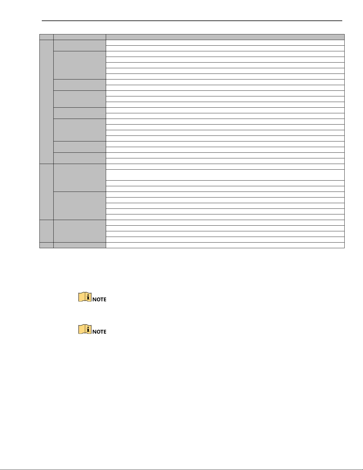
No. Name
Function Description
1 POWER
Turns green when DVR is powered up
READY
Turns
green, indicating that
the DVR is functioning properly
T
urns
green
when devic
e is controlled by an IR remote
T
urns red when controlled by a keyboard a
nd purple when IR remote and
ke
yboard is used at the same time
ALARM
Turns red
when a sensor alarm is detected
HDD Flickers
red when data is be
ing read from or written to HDD
Tx/Rx Flickers
green when network connection is functio
ning properly
2
DVD-R/W Slot for DVD
-
R/W
Switches between the numeric
or
letter input and
functions of the composite
light is red.)
Enters
numeral “1”
Access
es the main menu interface
Enters
numeral “2”
Enters
letters “ABC”
The F1 button when used in a list field will select all items in the list
Turns
on/off
PTZ light
i
n PTZ Control mode,
and use
it
to
zoom out the image
Switches
betw
een main and spot video output
in live view or playback mode
.
Enters
numeral “3”
Enters
letters “DEF”
Uses the
F2 button is used to change the tab pages
Zooms in the image
in PTZ control mode
Enters
numeral “4”
Enters letters “GHI”
Exits
and back to the previous menu
Enters
numeral “5”
Enters
letters “JKL”
Delete
s characters before cursor
Check the checkb
ox and select the ON/OFF switch
Starts/stops
record clipping in playback
Enters
numeral “6”
Enters
letters “MNO”
Accesses
to playback interface
in Playback mode
Enters
numeral “7”
Enters
letters “PQRS”
A
ccesses
to manual record interface
M
anually enable
s
/disable
s record
Enters
numeral “8”
Enters
letters “TUV”
Access
es PTZ control interface
Enters
numeral “9”
Enters
letters “WXYZ”
Multi-channel
display in
live view
0/A Enters
numeral
“0”
NOTE: Figures in this manual are for illustration only; your screens may differ.
1 Introduction
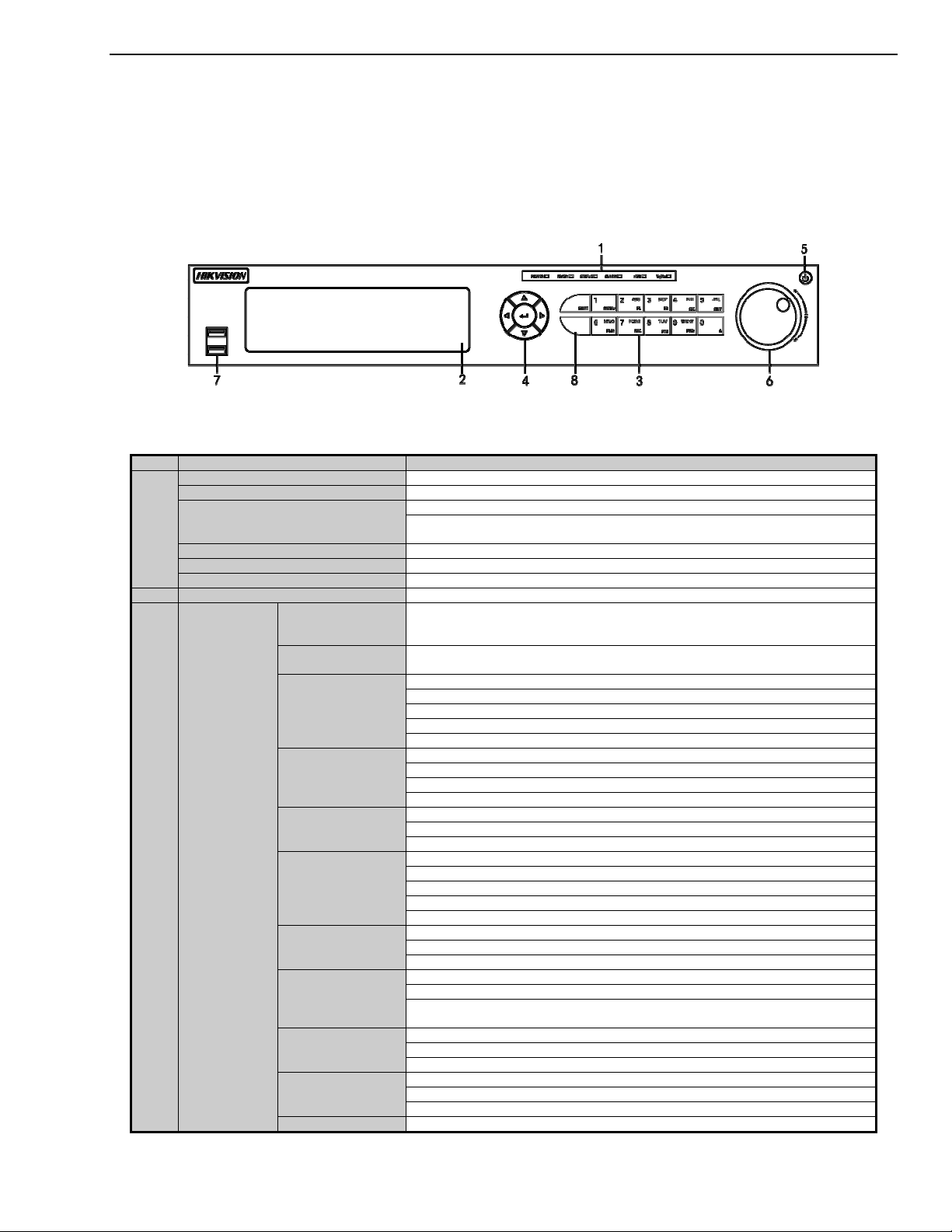
1.1 Front Panel
Figure 1, DS-73xxHUI-K4, DS-73xxHQI-K4 Front Panel
Table 1-1 DS-73xxHUI-K4, DS-73xxHQI-K4 Front Panel Description
STATUS
SHIFT
1/MENU
2/ABC/F1
3/DEF/F2
4/GHI/ESC
Composite
3
Keys
5/JKL/EDIT
6/MNO/PLAY
keys. (Input letter or numbers when the light is out; Realize functions when the
7/PQRS/REC
8/TUV/PTZ
9/WXYZ/PREV
UM DS-73xxHUI-K4 DS-73xxHQI-K4 DS-90xxHUI-K8 032918NA 16
DS-73xxHUI-K4, DS-73xxHQI-K4, DS-90xxHUI-K8 DVR User Manual
No. Name
Function Description
Shifts
the input methods in the editing text field. (
Upper and lowercase,
alphabet, symbols or numeric input).
N
avigate
s between diffe
rent fields and items in menus
Uses
the Up and Down button
s to speed up and slow down
the playing of
video
The Left and Right button wi
ll select the next and previous record files.
Cycles
through channels
in Live View mode
. C
ontrol
s the movement of the PTZ camera
in PTZ control mode
C
onfirm
s selection in any of
the menu modes
Checks the
checkbox
P
lays
or pause
s the pla
ying of
video
files i
n Playback mode
Advance
s the video by a single frame
in single
-
frame Playback mode
Stops/start
s auto switch
in Auto
-
switch mode
5
POWER
Power on/off switch
Move
s the active selection
up and down
in a menu
C
ycles
through different channels
in live view mode
Jumps
30s forward/backward in video files
in
the playback mode
Control
s the movement of the PTZ camera
in PTZ control mode
Move
s the active selection
up and down
in a menu
U
niversal Serial Bus (USB) ports for additional devices such as USB mous
e and
USB Hard Disk Drive (HDD)
8
IR Receiver
Receiver for IR remote
control
No. Name
Function Description
1 ALARM
Red when a sensor alarm is detected
READY
Blue, indicating that the DVR is functioning properly
B
lue when device is controlled
by an IR remote
Red when controlled by a keyboard and purple when IR remote and ke
yboard is used at the same time
HDD Flickers red when data is be
ing read from or written to HDD
MODEM
Flickers blue when network connection is function
ing properly
Tx/Rx
Blue when the device is in armed status; at this time, an alarm is enabled when an event is detected.
Tu
rns off when the device is unarmed. The arm/disarm status can be changed by pressing and holding on
the ESC button for more than 3 seconds in live view mode.
Red when a sensor alarm is detected
2
IR Receiver
Receiver for IR remote
3
Front Panel Lock
Lock or unlock the panel by the key
4
DVD-R/W Slot for DVD
-
R/W
Switches to the corresponding channel in live view or PTZ c
ontrol mode
Inputs numbers and characters in e
dit mode
Switches between different channels in p
layback m
ode
B
lue when the corresponding channel is recording; turns red when the channel is in network transmission
status; turns pink when the channel is recording and transmitting.
6
USB Interfaces
Universal Serial Bus
ports for additional devices such as US
B mous
e and USB Hard Disk Drive (HDD)
Returns
to the previous menu
Presses for arming/disarming the device in live v
iew mode
Enters t
he Manual Record settings menu
Presses this button followed by a numeric button to call a PTZ prese
t in PTZ control settings
Turns audio on/off in the p
layback mode
Enters the p
layback mode
Automatically scans in the PTZ c
ontrol menu
ZOOM+
Zooms in the PTZ camera in the PTZ c
ontrol setting
DIRECTION
4
ENTER
6 JOG SHUTTLE Control
7 USB Interface
files in Playback mode.
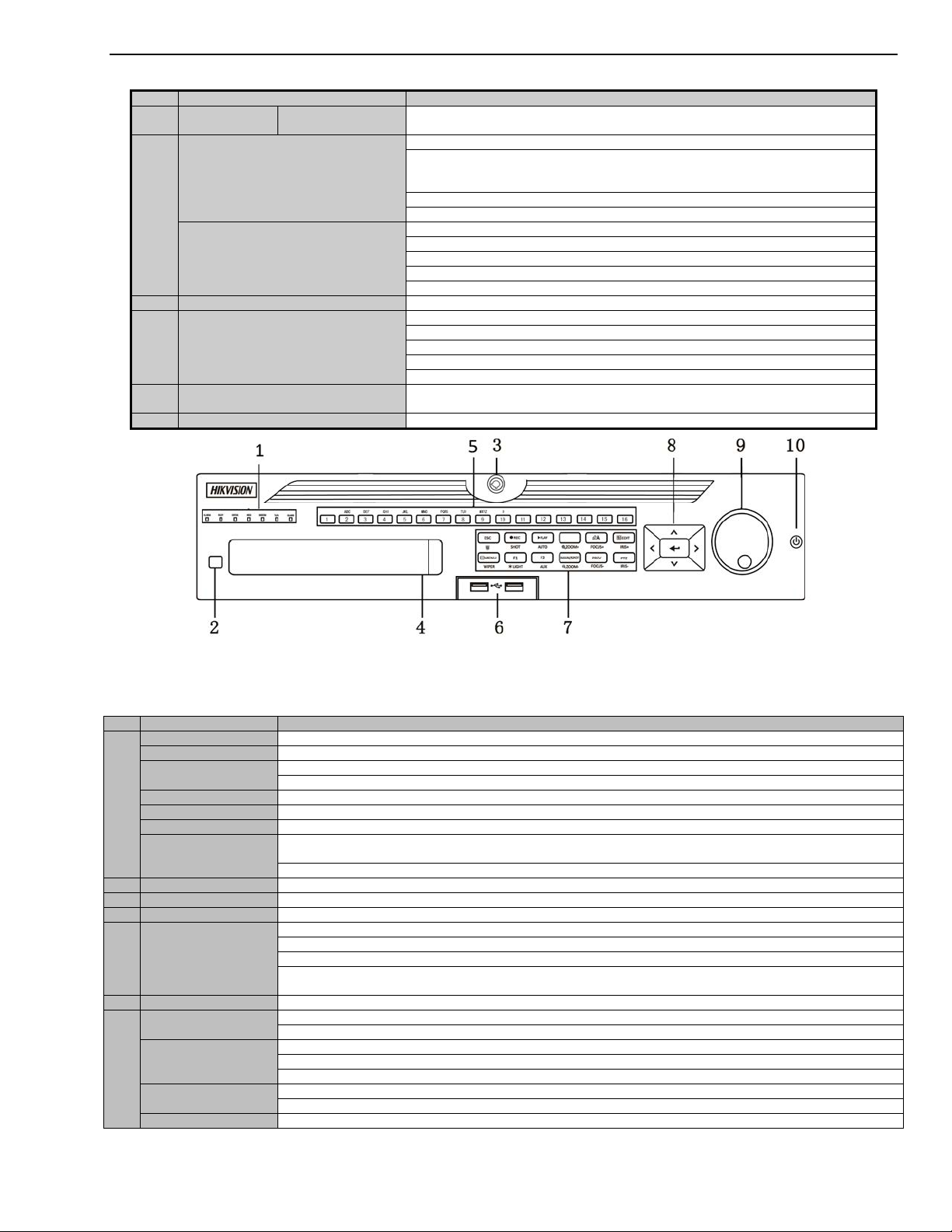
Figure 2, DS-90xxHUI-K8 Front Panel
Table 1-2 DS-90xxHUI-K8 Front Panel Description
STATUS
GUARD
Alphanumeric
5
Buttons
ESC
REC/SHOT
7
PLAY/AUTO
UM DS-73xxHUI-K4 DS-73xxHQI-K4 DS-90xxHUI-K8 032918NA 17
DS-73xxHUI-K4, DS-73xxHQI-K4, DS-90xxHUI-K8 DVR User Manual
No. Name
Function Description
Adjusts
focus in the PTZ Control
menu
Switches between input methods (upper and lower case alphabet, symbol
s and numeric input).
Edits text fields. When editing text fields, it also deletes the ch
aracter in front of the cursor
Checks the checkbox in the checkbox fields
Adjusts the iris of the camera in PTZ control mode
Generates video clips for backup in playback mode
Enters/exits the fol
der of USB device and eSATA HDD
Switches
between main and spot output
Zooms out the image in PTZ control
mode
Selects all items on the list when used in a list
field
Turns on/off PTZ light
(if applicable) in PTZ control mode
Switches between play and reverse play in playback mode
Cycles
through tab pages
Switches between channel
s in synchronous playback mode
Returns to the Mai
n menu (after successful login)
Presses and holds the button for five seconds to
turn off audible key beep
Starts wiper (if applicable) in PTZ control mode
Shows/hides the control inter
face in playback mode
Switches between singl
e screen and multi
-
screen mode
Adjusts the focus in conjunction with the A/FOCUS+ button in PTZ control mode
Enters
the PTZ Control mode
Adjusts the iris of the PTZ camera in PTZ c
ontrol mode
Navigates between different f
ields and items in menus
Uses the Up and Down buttons to speed up and slow down the playing of video files in Playback mode.
The Left and Right button will select the next and previous record files.
Cycles through channels in Live View mode
Controls the movement of the PTZ camera in PTZ control mode
Confirms sele
ction in any of the menu modes.
Checks the checkbox
Plays or pauses the playing of video files in Playback mode
Advanc
es the video by a single frame in single
-
frame Playback mode
Stops/starts auto switch in Auto
-
switch mode
Moves the active selection up and down
in a menu
Cycles through different channels in live view mode
Jumps 30s forwar
d/backward in video files in the playback mode
Controls the movement of the PTZ camera in PTZ control mode
10
POWER ON/OFF
Power o
n/off switch
A/FOCUS+
EDIT/IRIS+
MAIN/SPOT/ZOOM-
F1/ LIGHT
F2/ AUX
MENU/WIPER
PREV/FOCUS-
PTZ/IRIS-
DIRECTION
8
ENTER
JOG SHUTTLE
9
Control
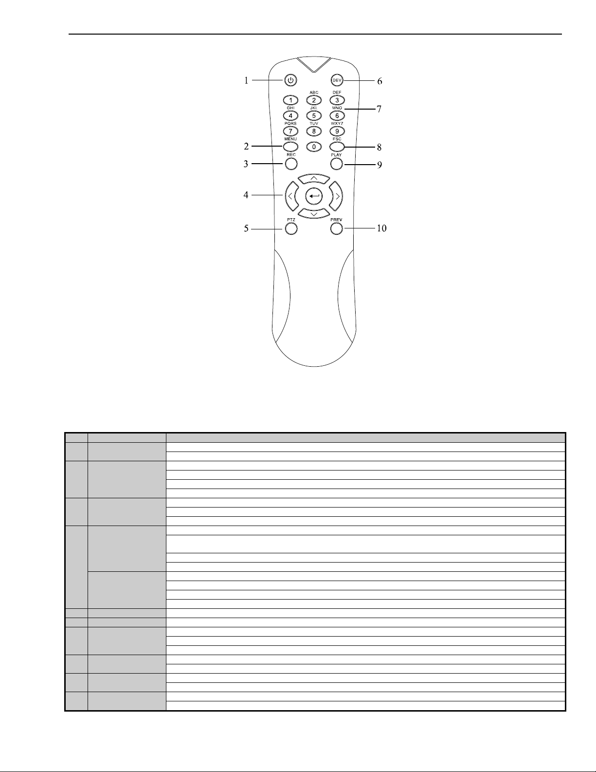
1.2 IR Remote Control Operations
The DVR may also be controlled with the included IR remote control.
If your system is secured with a password pattern, press ESC on the remote to display
the password input window and input the password by using a keyboard.
Batteries (2 × AAA) must be installed before operation.
UM DS-73xxHUI-K4 DS-73xxHQI-K4 DS-90xxHUI-K8 032918NA 18
DS-73xxHUI-K4, DS-73xxHQI-K4, DS-90xxHUI-K8 DVR User Manual
No. Name
Description
Power on/off the device.
Power on/off the
device
by pressing and holding the button for
5 seco
nds.
Press the button
to return to the
m
ain menu (after successful login).
Press and hold the button for 5 seconds will turn off audible key beep.
In PTZ Control mode, the MENU button will start wiper (if applicable).
In Playback mo
de, it is used to show/hide the control interface.
Enter the Manual Record setting menu.
In PTZ control settings, press the button and then you can call a PTZ preset by pressing Numeric button.
It is also used to turn audio on/off in th
e Playback mode.
N
avigate between different fields and items in menus.
In the Playback mode, the Up and Down button is used to speed up and slow down recorded video. The Left
and Right button will select the next and previous record
files. In Live View mode, these buttons can be used to cycle through channels.
In PTZ control mode, it can control the movement of the PTZ camera.
C
onfirm selection in any of the menu modes.
It can also be used to
tick
checkbox fie
lds. In Playback mode, it can be used to play or pause the video.
In single
-
frame Playback mode, pressing the button will advance the video by a single frame.
5
PTZ Button
In Auto
-
switch mode, it can be used to stop /start auto switch.
6
DEV Enabl
es/Disables Remote Control.
Switch to the corresponding channel in Live view or PTZ Control mode.
Input numbers and characters in Edit mode.
Switch between different channels in
the Playback mode.
Back to the pre
vious menu.
Press for Arming/disarming the device in Live View mode.
The button is used to enter the All
-
day Playback mode.
It is also used to
auto scan in the PTZ Control menu.
Switch between single screen and multi
-screen mode.
In PTZ Control mode, it is used to adjust the focus in conjunction with the A/FOCUS+ button.
Figure 3, Remote Control
The keys on the remote control resemble the ones found on the front panel. See Table 1-3.
Table 1-3 Description of the IR Remote Control Buttons
1 POWER
2 MENU Button
3 REC Button
DIRECTION Button
4
ENTER Button
Alphanumeric
7
Buttons
8 ESC Button
9 PLAY Button
10 PREV Button
UM DS-73xxHUI-K4 DS-73xxHQI-K4 DS-90xxHUI-K8 032918NA 19
DS-73xxHUI-K4, DS-73xxHQI-K4, DS-90xxHUI-K8 DVR User Manual
Name
Action
Description
Live view: Select channel and show the quick set menu.
Menu: Select
and enter.
Double
-
Click Live view: Switch between single
-
screen and multi
-
screen.
PTZ control: Wheeling.
Live view: Drag channel/time bar.
Live view: Show menu.
Menu: Exit current menu to upper level menu.
Live view: Previous screen.
Menu: Previous item.
Live view: Next screen.
Menu: Next item.
1.2.1 Troubleshooting Remote Control
Make sure batteries have been installed properly. Also, note that the
remote control must be aimed at the IR receiver on the NVR front panel.
If there is no response after pressing any button on the remote, follow
the procedure below to troubleshoot.
1. Go to M
enu > Configuration > General > More Settings by operating the
front control panel or the mouse.
2. Check and remember the DVR No. The default DVR No. is 255. This
number valid for all IR remote controls.
3. Press DEV on the remote control.
4. Enter the DVR No. in Step 2.
5. Press ENTER on the remote.
If the front panel Status indicator turns blue, the remote control is operating
properly. If the Status indicator does not turn blue and there is no response,
check the following:
• Batteries are installed correctly and the polarities are not reversed.
• Batteries are fresh and not out of charge.
• IR receiver is not obstructed.
f the remote still does not function, change the remote and try again, or
I
contact the device provider.
1.3 USB Mouse Operation
A regular 3-button (Left/Right/Scroll-wheel) USB mouse can also be used with this DVR.
1. Plug mouse into a USB interface on the DVR. The mouse should automatically be
detected. If not, the mouse might not be compatible. Refer to your mouse provider.
Table 1-4 Description of the Mouse Control
Single-Click
Left-Click
Drag
Right-Click Single-Click
Scrolling up
Scroll-Wheel
Scrolling down
UM DS-73xxHUI-K4 DS-73xxHQI-K4 DS-90xxHUI-K8 032918NA 20
Privacy mask and motion detection: Select target area.
Digital zoom-in: Drag and select target area.
DS-73xxHUI-K4, DS-73xxHQI-K4, DS-90xxHUI-K8 DVR User Manual
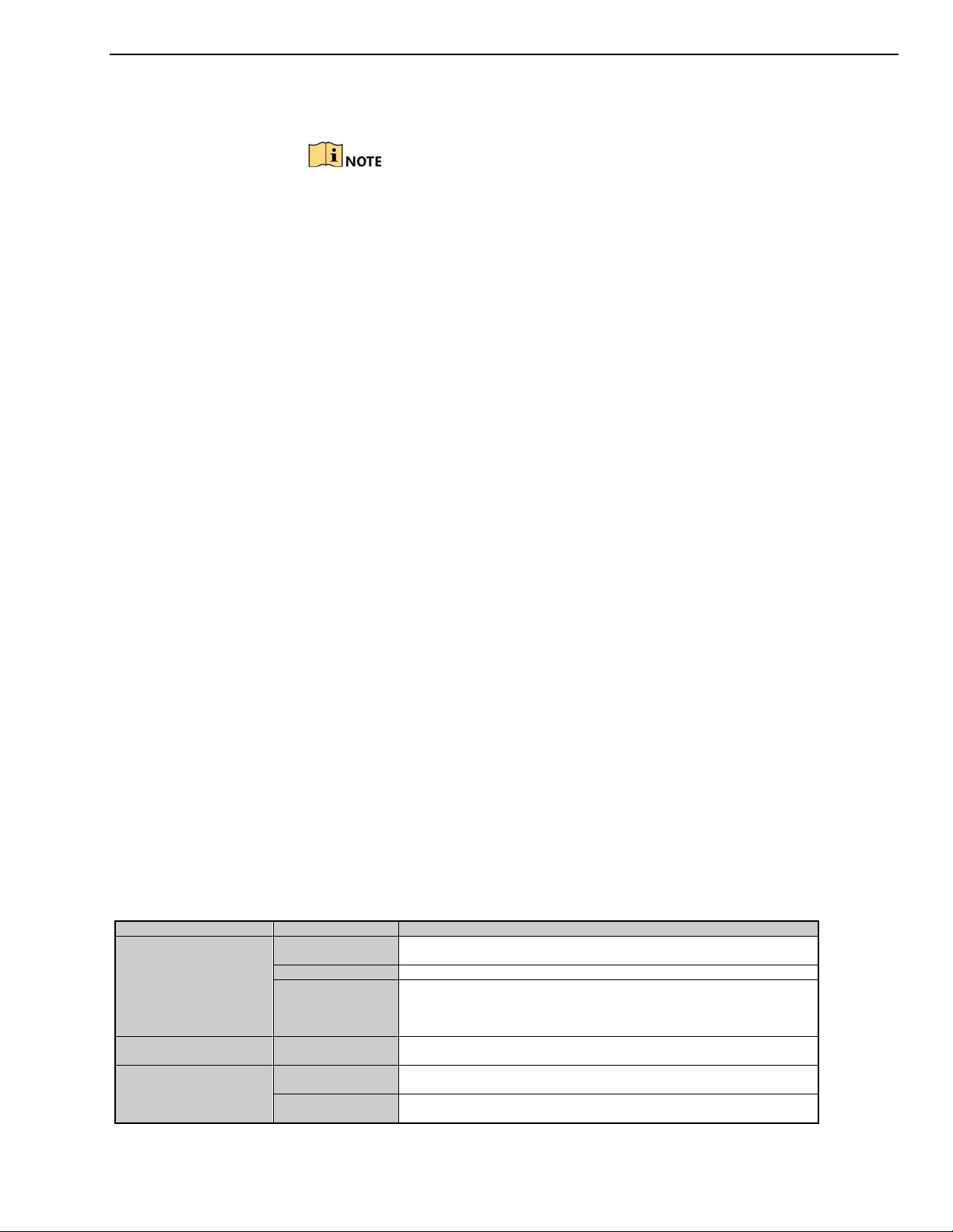
1.4 Input Method Description
Figure 4, Soft Keyboard
Description of the buttons on the soft keyboard:
Table 1-5 Description of the Soft Keyboard Icons
Icon Description Icon Description
…
Number
Lowercase/Uppercase
Switch the keyboard
Positioning the cursor
Symbols
…
English letter
Backspace
Space
Enter
Reserved
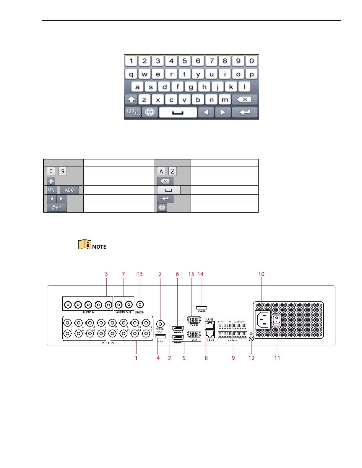
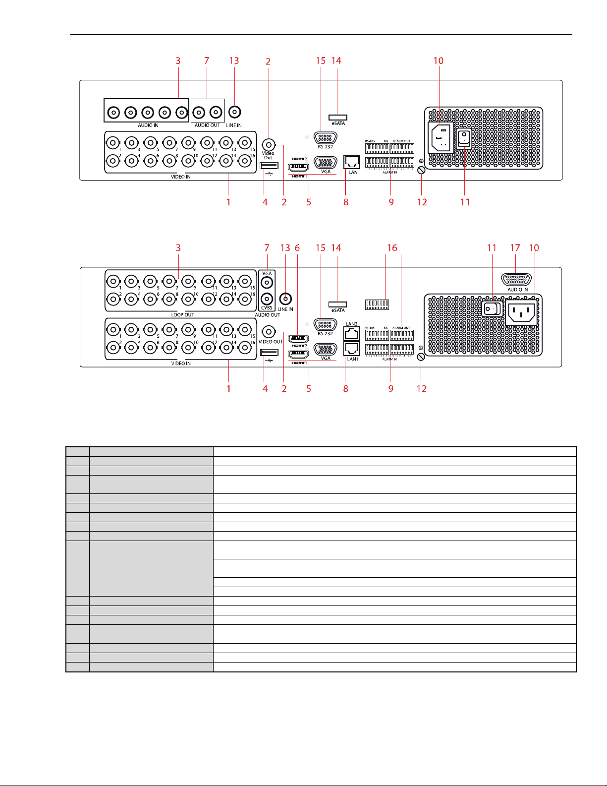
1.5 Rear Panel
The rear panel varies by model. Refer to the actual product. The following figures are
for reference only.
Figure 5, DS-7316HUI-K4 Rear Panel
(DS-7304HUI-K4 = 4 Video In, DS-7308HUI-K4 = 8 Video In, DS-7332HUI-K4 = 32 Video In)
UM DS-73xxHUI-K4 DS-73xxHQI-K4 DS-90xxHUI-K8 032918NA 21
DS-73xxHUI-K4, DS-73xxHQI-K4, DS-90xxHUI-K8 DVR User Manual
No. Item Description
1
VIDEO IN
BNC interface for
Turbo
HD and analog
video input.
2
VIDEO OUT
BNC connector for video output.
AUDIO IN
/LOOP OUT (for
DS-90xxHUI-K8)
4 USB Port
Universal Serial Bus (USB) port for additional devices
. 5 HDMI1/VGA
Simultaneous
HDMI1/
VGA out
put. Display local video output and menu.
6
HDMI2
HDMI2 video output connector
(DS-73xxHUI
-
K4 and DS
-
90xxHUI
-
K8) 7 AUDIO OUT
RCA connector
8
Network
Interface
Connector for
network
(DS-73xxHUI
-
K4 and DS
-
90xxHUI
-
K8 = x2, DS
-
73xxHUI
-
K4 = x1)
Connector for RS
-
485 devices. T+
and T-
pins
connect to
R+ and R
- pins of
PTZ receiver
respectively
.
D+, D-
pin connects to Ta, Tb pin of controller. For cascading devices, the first
D
VR’s D+, D
- pin
should be connected with the D+, D
- pin of the next
D
VR. Connector for alarm input
Connector for alarm output
10
Power Supply
100 to
240 V
AC power supply
11
Power Switch
Switch for turn
ing on/off the device
12
GND Ground
13
LINE IN
BNC connector for audio input
14
eSATA
Connects e
xternal SATA HDD, CD/DVD
-RW 15 RS-232 Interface
Connector for RS
-
232 devices
16
ALARM OUT
Connector for alarm output
17 AUDIO IN (for DS
-90xxHUI-K8) RCA connector
Figure 6, DS-7316HQI-K4 Rear Panel
(DS-7308HQI-K4 = 8 Video In, DS-7332HQI-K4 = 32 Video In)
Figure 7, DS-9016HUI-K8 Rear Panel
(DS-9008HUI-K8 = 8 Video In, DS-9032HUI-K8 = 32 Video In)
Table 1-6 Description of DS-73xxHUI-K4, DS-73xxHQI-K4, and DS-
3
9 RS-485 and Alarm Interface
RCA connector
90xxHUI-K8 Rear Panel
UM DS-73xxHUI-K4 DS-73xxHQI-K4 DS-90xxHUI-K8 032918NA 22
DS-73xxHUI-K4, DS-73xxHQI-K4, DS-90xxHUI-K8 DVR User Manual
2 Getting Started
2.1 Starting Up and Shutting Down the DVR
Purpose
Proper startup and shutdown procedures are crucial to expanding the life of the DVR.
Before You Start
Check that the voltage of the power supply is the same with the DVR’s requirement, and
the ground connection is working properly.
2.1.1 Starting the DVR
Check that the power supply is plugged into an electrical outlet. It is
HIGHLY recommended that an Uninterruptible Power Supply (UPS) be
used in conjunction with the device.
Turn on the power switch on the rear panel, and the Power indicator LED
should turn on indicating that the unit begins to start up.
After startup, the Power indicator LED remains on.
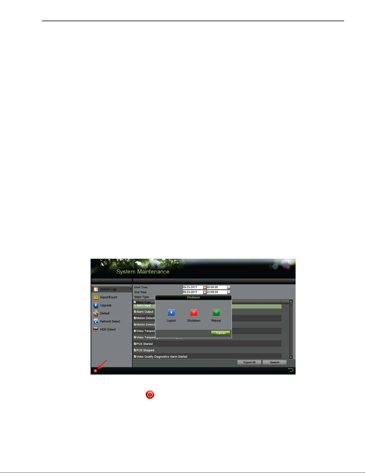
2.1.2 Shutting Down/Logging Out/Rebooting the DVR
1. Go to Menu > Maintenance.
Figure 8, Shutdown Menu
2. Click
3. Click one of the following:
• Logout – Logs the current user out of the system.
UM DS-73xxHUI-K4 DS-73xxHQI-K4 DS-90xxHUI-K8 032918NA 23
(lower left corner of screen) to display the Shutdown window.
DS-73xxHUI-K4, DS-73xxHQI-K4, DS-90xxHUI-K8 DVR User Manual
• Shutdown – Shuts system down.
• Reboot – Shuts system down and reboots.
• Cancel – Cancels shutdown.
4. Click Yes.
5. Turn off the power switch on the rear panel.
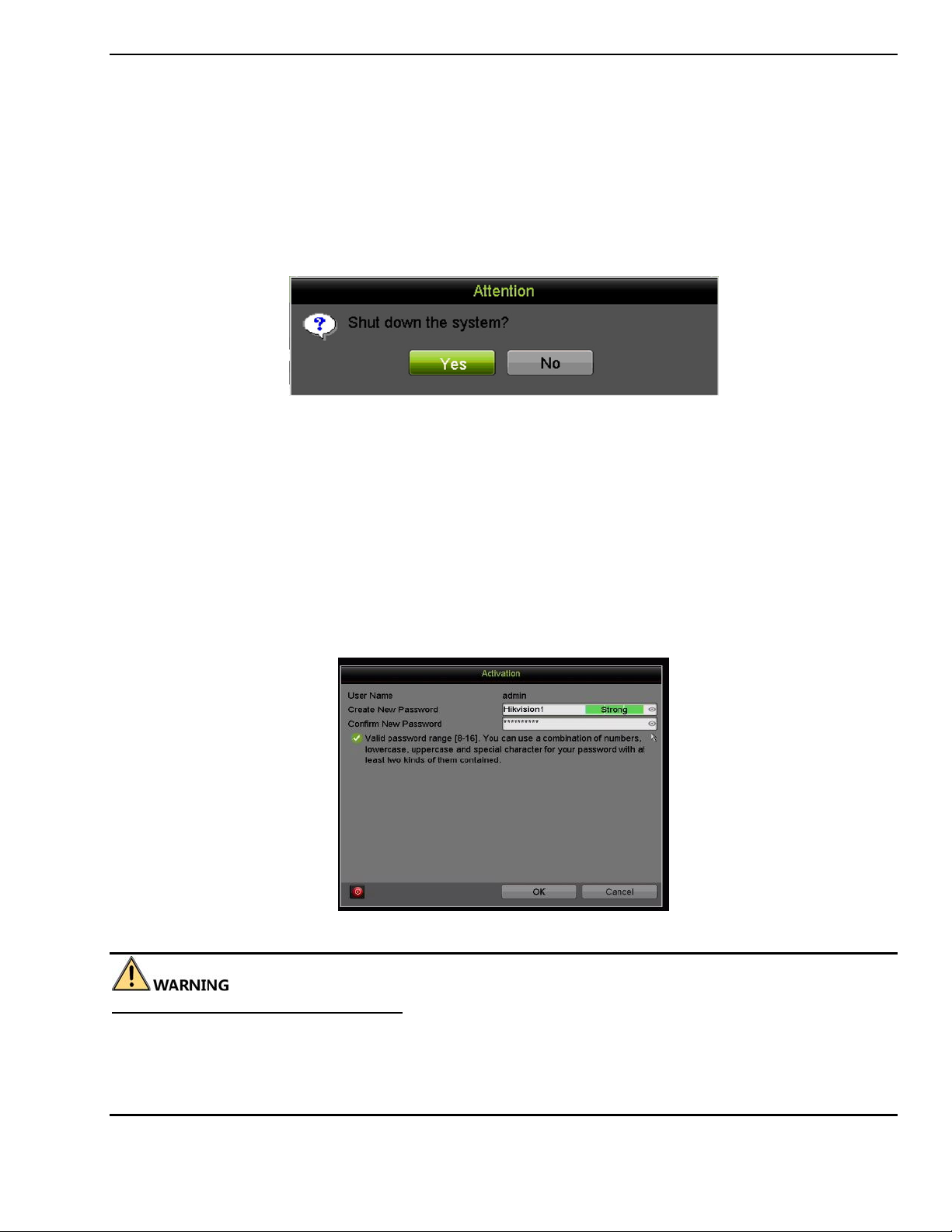
Figure 9, Shutdown Prompt
2.2 Activating the Device
Purpose
For the first-time access, you need to activate the device by setting an admin password. No
operation is allowed before activation. You can also activate the device via Web Browser,
SADP, or Client Software.
1. Input the same password in the Create New Password and Confirm New Password
text fields.
Figure 10, Settings Admin Password
STRONG PASSWORD RECOMMENDED – We highly recommend you create a strong password of your
own choosing (using a minimum of eight characters, including at least three of the following categories:
upper case letters, lower case letters, numbers, and special characters) in order to increase the security
of your product. We also recommend that you reset your password regularly. Especially in high security
systems, resetting the password monthly or weekly can better protect your product.
UM DS-73xxHUI-K4 DS-73xxHQI-K4 DS-90xxHUI-K8 032918NA 24
DS-73xxHUI-K4, DS-73xxHQI-K4, DS-90xxHUI-K8 DVR User Manual
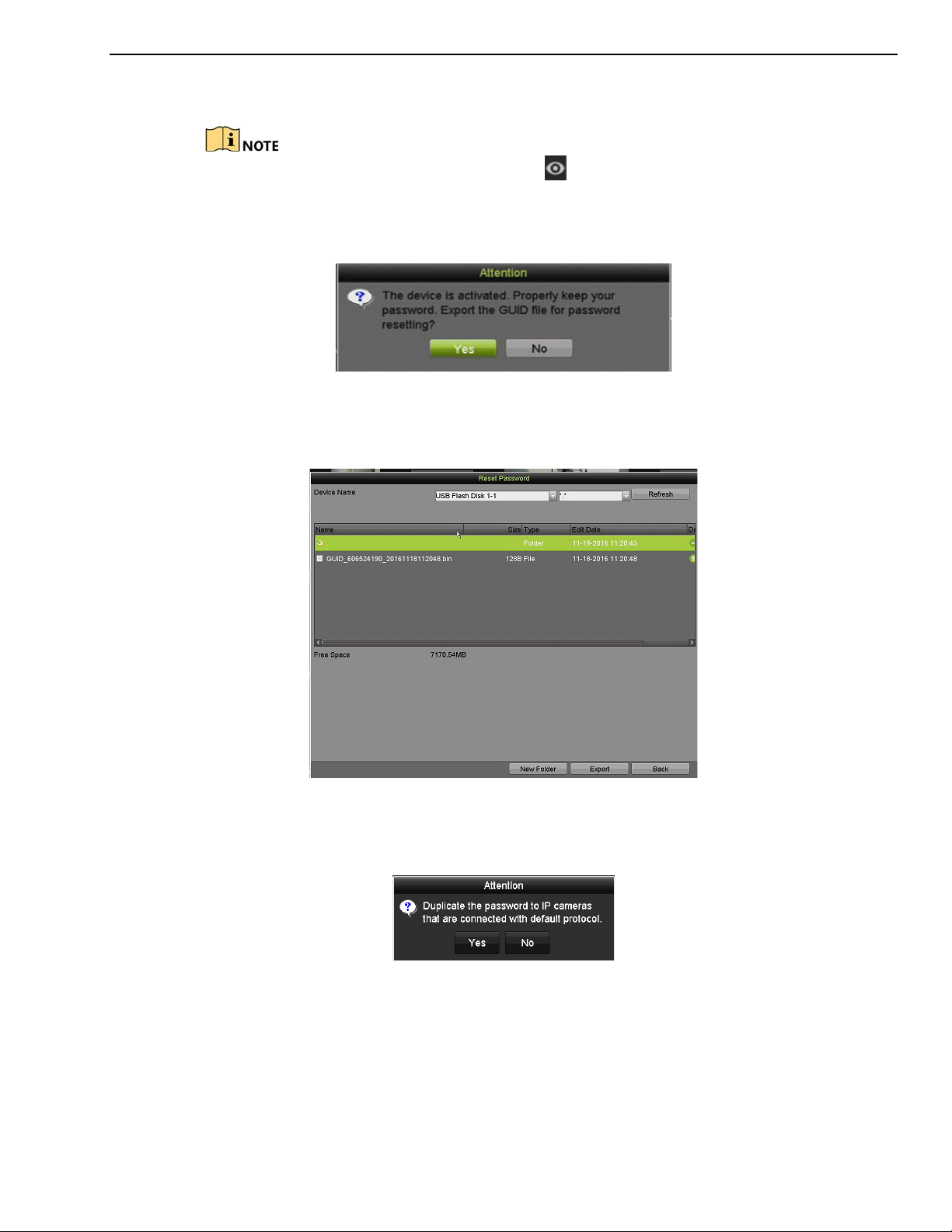
2. Click OK to save the password and activate the device.
Clear text password is supported. Click to see the clear text of the password. Click
the icon again and the password again becomes invisible.
3. After the device is activated, the Attention box pops up as below.
Figure 11, Attention Window
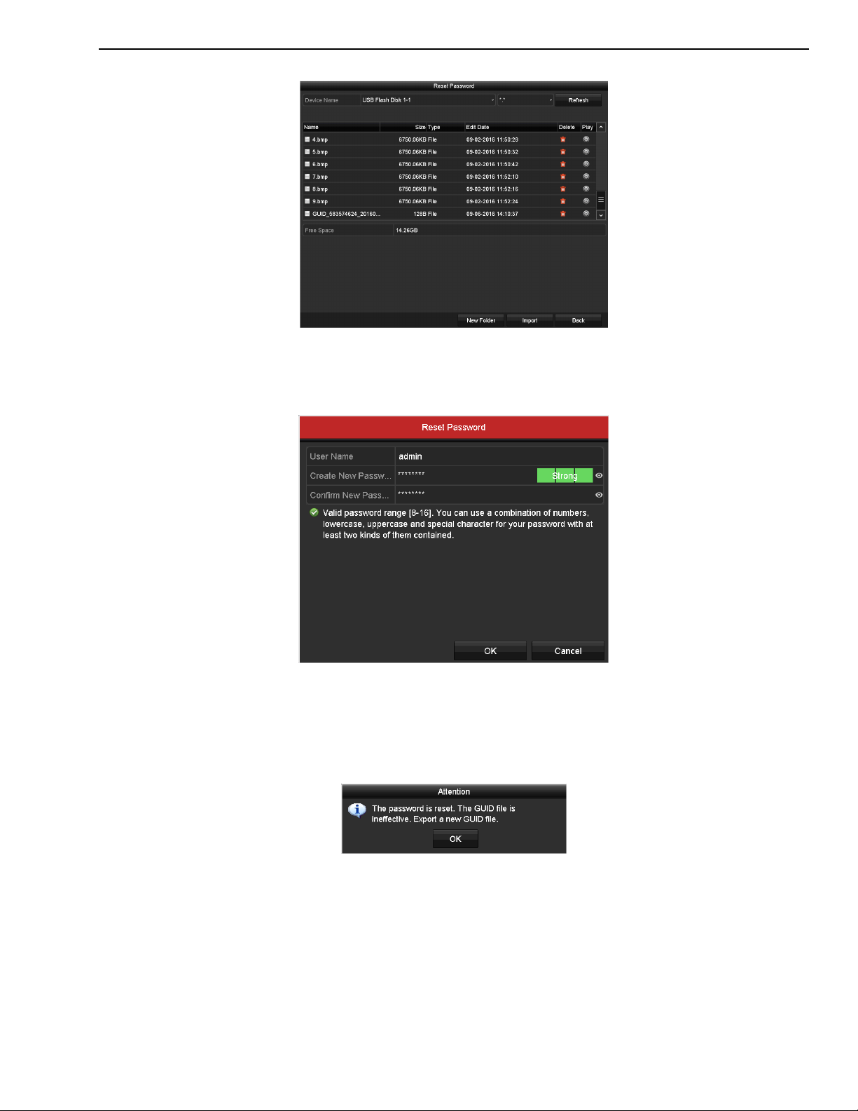
4. (Optional) Click Yes to export the GUID. The Reset Password interface pops up. Click
Export to export the GUID to the USB flash drive for password resetting.
Figure 12, Export GUID
5. After exporting the GUID, the Attention box pops up as below. Click Yes to duplicate
the password or No to cancel it.
Figure 13, Duplicate the Password
2.3 Using the Unlock Pattern for Login
Purpose
An admin can configure an unlock pattern for device login.
UM DS-73xxHUI-K4 DS-73xxHQI-K4 DS-90xxHUI-K8 032918NA 25
DS-73xxHUI-K4, DS-73xxHQI-K4, DS-90xxHUI-K8 DVR User Manual
2.3.1 Configuring the Unlock Pattern
After the device is activated, enter the following interface to configure the
device unlock pattern.
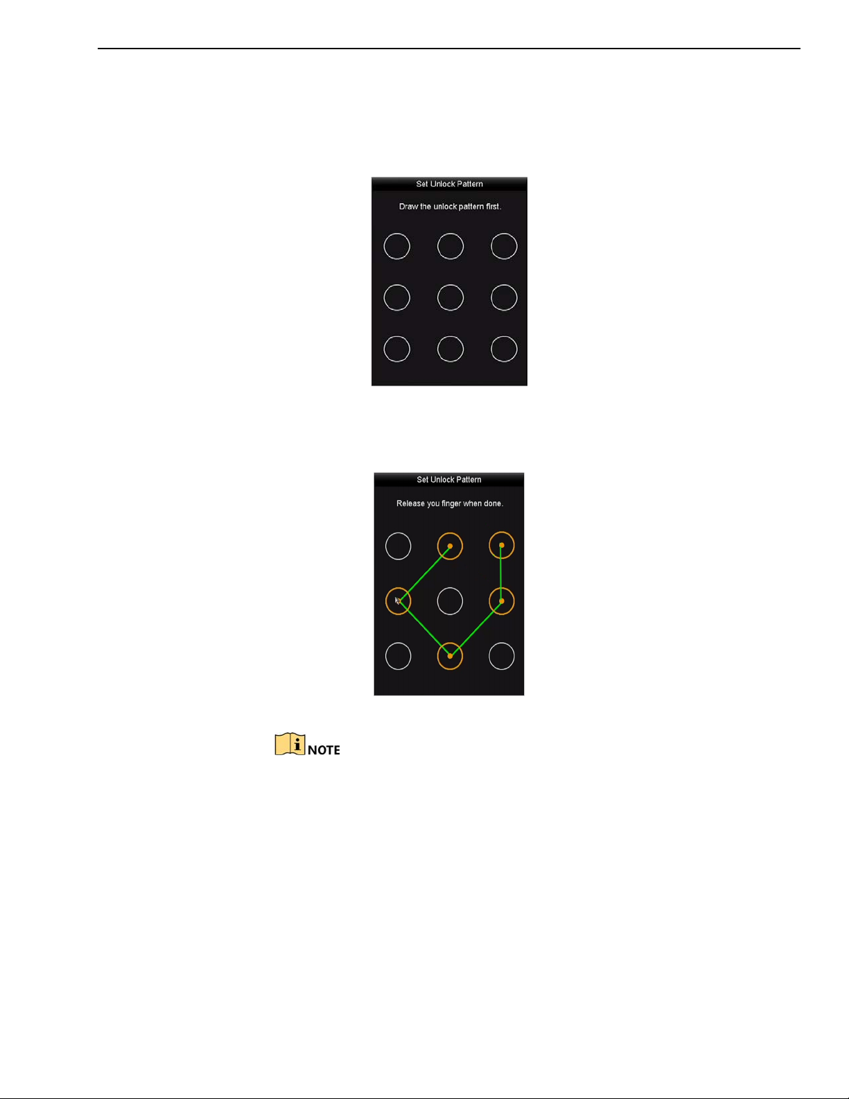
Figure 14, Set Unlock Pattern
1. Use the mouse to draw a pattern among the nine dots on the screen.
Release the mouse when the pattern is done.
Figure 15, Draw the Pattern
Connect at least four dots to draw the pattern.
Each dot can be connected only once.
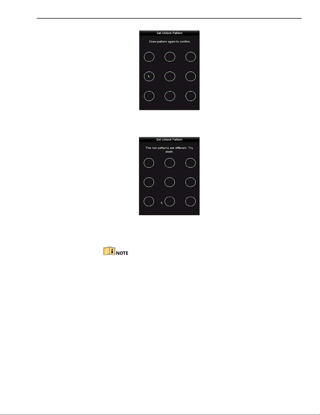
2. Draw the same pattern again to confirm it. When the two patterns match,
the pattern is configured successfully.
UM DS-73xxHUI-K4 DS-73xxHQI-K4 DS-90xxHUI-K8 032918NA 26
DS-73xxHUI-K4, DS-73xxHQI-K4, DS-90xxHUI-K8 DVR User Manual
Figure 16, Confirm the Pattern
If the two patterns are different, you must set the pattern again.
Figure 17, Reset the Pattern
2.3.2 Logging in via Unlock Pattern
Only the admin user has the permission to unlock the device.
Configure the pattern first before unlocking.
1. Right-click the mouse on the screen and select the menu to enter the
interface.
UM DS-73xxHUI-K4 DS-73xxHQI-K4 DS-90xxHUI-K8 032918NA 27
DS-73xxHUI-K4, DS-73xxHQI-K4, DS-90xxHUI-K8 DVR User Manual
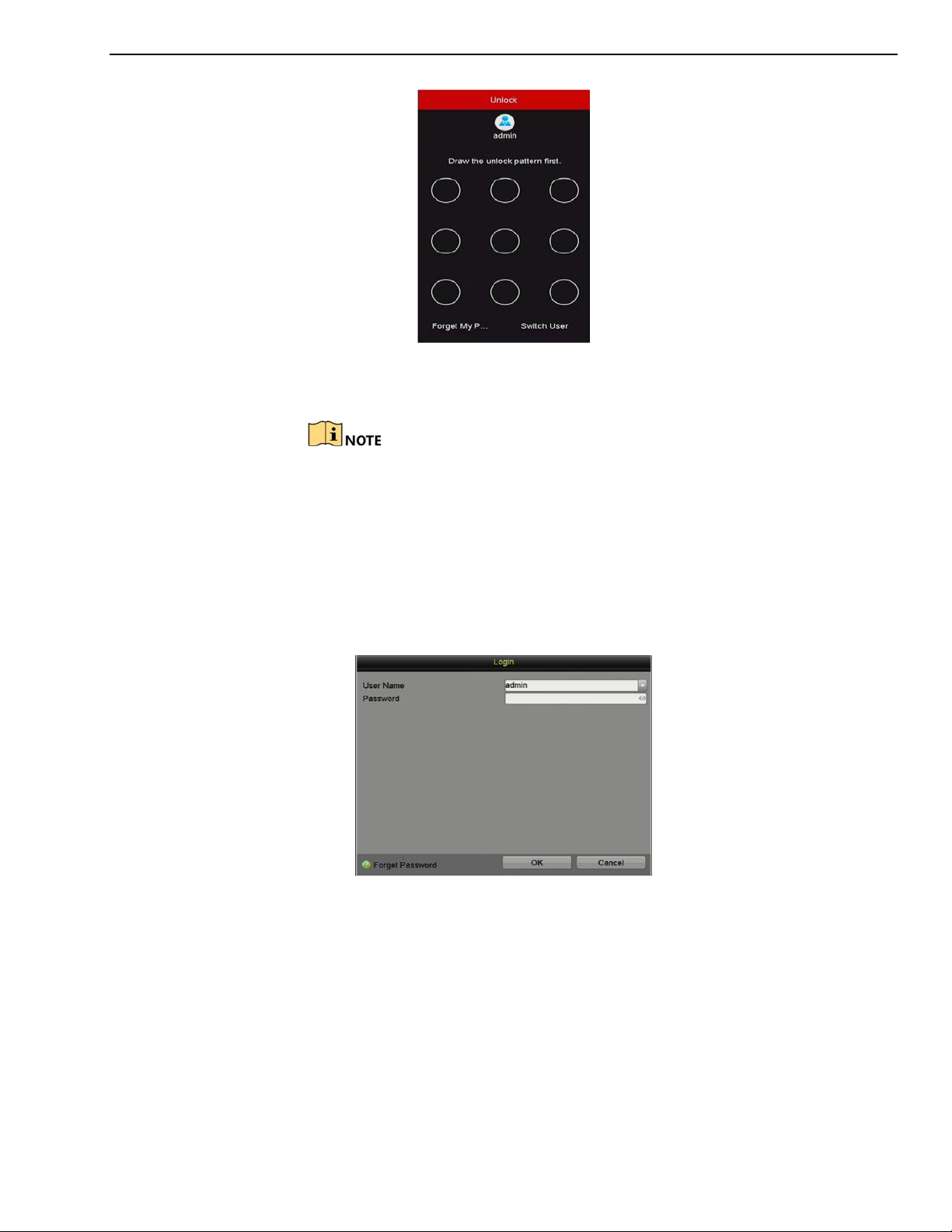
Figure 18, Draw the Unlock Pattern
2. Draw the pre-defined pattern to unlock to enter the menu operation.
You can right click the mouse to log in via the normal mode.
If you have forgotten your pattern, you can select the Forget My Pattern
or Switch User option to enter the normal login dialog box.
When the pattern you draw is different from the pattern you have
configured, try again.
If you draw the wrong pattern seven times, the account will lock for one
minute.
Figure 19, Normal Login Dialog Box
2.3.3 Login and Logout
2.3.3.1 User Login
Purpose
You must log in to the device before operating the menu and
other functions.
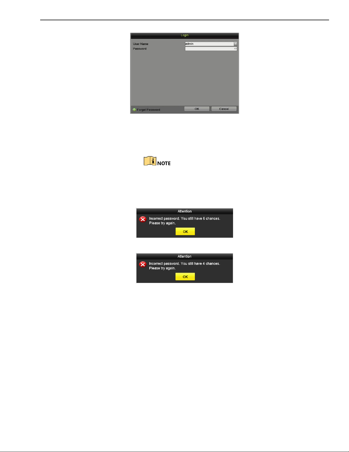
1. Select the User Name in the drop-down list.
UM DS-73xxHUI-K4 DS-73xxHQI-K4 DS-90xxHUI-K8 032918NA 28
DS-73xxHUI-K4, DS-73xxHQI-K4, DS-90xxHUI-K8 DVR User Manual
Figure 20, Login Interface
2. Input the Password.
3. Click OK to log in.
In the Login interface, for the admin user, if you have entered
the wrong password seven times, the account will be locked
for 60 seconds. For operators, if you have entered the wrong
password for five times, the account will be locked for 60
seconds.
Figure 21, User Account Protection for the Admin
Figure 22, User Account Protection for the Operator
2.3.4 Resetting Your Password
Purpose
If you forget the admin password, you can reset the password by importing
the GUID file, which was exported and saved in the local USB flash drive after
you activated the device.
1. On the user login interface, click Forget Password to enter the Import
GUID interface.
UM DS-73xxHUI-K4 DS-73xxHQI-K4 DS-90xxHUI-K8 032918NA 29
DS-73xxHUI-K4, DS-73xxHQI-K4, DS-90xxHUI-K8 DVR User Manual
Figure 23, Import GUID
2. Select the GUID file from the USB flash drive and click Import to pop up
the Reset Password interface.
Figure 24, Reset Password
3. Input the new password and confirm the password.
4. Click OK to save the new password. Then the Attention box pops up as
shown below.
Figure 25, GUID File Imported
5. Click OK and the Attention box as below pops up to remind you to
duplicate the password of the device to IP cameras that are connected
with default protocol. Click Yes to duplicate the password or No to cancel
it.
UM DS-73xxHUI-K4 DS-73xxHQI-K4 DS-90xxHUI-K8 032918NA 30

DS-73xxHUI-K4, DS-73xxHQI-K4, DS-90xxHUI-K8 DVR User Manual
Figure 26, Duplicate the Password
To retrieve a forgotten password, you must export th
Once the password is reset, the GUID file will be invalid. You can export a
new GUID file.
2.3.5 Adding and Connecting IP Cameras
2.3.5.1 Activating an IP Camera
Purpose
Before adding the camera, make sure the IP camera to be added is
in active status.
e GUID file first.
1. Select Add IP Camera from the right-click menu in live view
mode or go to Menu> Camera> IP Camera.
For the IP camera detected online in the same network
segment, the Security status shows whether it is active or
inactive.
Figure 27, IP Camera Management Interface
2. Click the inactive icon of the camera to enter the following
interface to activate it. You can also select multiple cameras
UM DS-73xxHUI-K4 DS-73xxHQI-K4 DS-90xxHUI-K8 032918NA 31

DS-73xxHUI-K4, DS-73xxHQI-K4, DS-90xxHUI-K8 DVR User Manual
from the list and click the One-touch Activate to activate the
cameras in batch.
Figure 28, Activate the Camera
3. Set the password of the camera to activate it.
Use Admin Password: If you check this checkbox, the camera(s)
will be configured with the admin password of the operating
DVR.
Create New Password: If the admin password is not used, you
must create a new password for the camera and confirm it.
Figure 29, Level 0 (Inadequate) Strength Password
UM DS-73xxHUI-K4 DS-73xxHQI-K4 DS-90xxHUI-K8 032918NA 32

DS-73xxHUI-K4, DS-73xxHQI-K4, DS-90xxHUI-K8 DVR User Manual
Figure 30, Invalid Password Message
Figure 31, Level 1 Password Strength
Figure 32, Level 2 Password Strength
UM DS-73xxHUI-K4 DS-73xxHQI-K4 DS-90xxHUI-K8 032918NA 33

DS-73xxHUI-K4, DS-73xxHQI-K4, DS-90xxHUI-K8 DVR User Manual
Figure 33, Level 3 and Level 4 Password Strength
STRONG PASSWORD RECOMMENDED − We highly recommend you create a strong password of your
own choosing (using a minimum of eight characters, including at least three of the following categories:
upper case letters, lower case letters, numbers, and special characters) in order to increase the security
of your product. We also recommend that you reset your password regularly. Especially in high security
systems, resetting the password monthly or weekly can better protect your product.
4. Click OK to finish activating the IP camera. The camera
security status will change to Active.
2.3.6 Adding an Online IP Camera
Purpose
Before you can get a live view or record of the video, add the network
cameras to the device’s connection list.
Before You Start
Ensure the network connection is valid and correct.
OPTION 1
1. Select Add IP Camera from the right-click menu in live view mode or
go to Menu > Camera > IP Camera.
UM DS-73xxHUI-K4 DS-73xxHQI-K4 DS-90xxHUI-K8 032918NA 34

DS-73xxHUI-K4, DS-73xxHQI-K4, DS-90xxHUI-K8 DVR User Manual
Figure 34, IP Camera Management Interface
2. Online cameras with the same network segment will be detected and
displayed in the camera list.
3. Select the IP camera from the list and click to add the camera
(with the same admin password of the DVR). Or you can click
One-touch Adding to add all cameras (with the same admin password)
from the list.
Make sure the camera to add has already been activated by setting the
admin password, and the admin password of the camera is the same as
the DVR’s.
4. (Optional) Check the Enable H.265 checkbox (for Initial Access) for
the connected IP camera supporting H.265. Then the IP camera will
be encoded with H.265.
5. (For encoders with multiple channels only) check the Channel Port
checkbox in the pop-up window, as shown in the following figure, and
click OK to add multiple channels.
UM DS-73xxHUI-K4 DS-73xxHQI-K4 DS-90xxHUI-K8 032918NA 35

DS-73xxHUI-K4, DS-73xxHQI-K4, DS-90xxHUI-K8 DVR User Manual
Figure 35, Select Multiple Channels
OPTION 2
1. On the IP Camera Management interface, click Custom Adding to pop
up the Add IP Camera (Custom) interface.
Figure 36, Custom Adding IP Camera Interface
2. You can edit the IP address, protocol, management port, and other
information of the IP camera to be added.
If the IP camera to add has not been activated, activate it from the IP
camera list on the IP Camera Management interface.
3. Click A
UM DS-73xxHUI-K4 DS-73xxHQI-K4 DS-90xxHUI-K8 032918NA 36
dd to add the camera.

DS-73xxHUI-K4, DS-73xxHQI-K4, DS-90xxHUI-K8 DVR User Manual
For successfully added IP cameras, the Security status shows the
security level of the camera password: strong password, weak
password, and risky password.
Figure 37, Successfully Added IP Cameras
UM DS-73xxHUI-K4 DS-73xxHQI-K4 DS-90xxHUI-K8 032918NA 37

DS-73xxHUI-K4, DS-73xxHQI-K4, DS-90xxHUI-K8 DVR User Manual
Icon
Explanation
Icon
Explanation
Table 1-7 Explanation of the Icons
EDIT (Pen): Press to edit basic IP camera
parameters
DISCONNECTED (!): Camera is
disconnected; click the icon to get camera’s
exception information
PLAY (Right Triangle): Play connected
camera’s live video
UPGRADE (Up Arrow): Upgrade the
connected camera’s firmware
REPAIR (?): Press to attempt to repair the
connection
Security
Column
ADD (+): Press to add the detected IP
camera
DELETE (Trash Can): Press to delete the
camera
ADVANCED (Gear): Press to go to
advanced settings window.
DASH: No advanced settings available for
this camera
SECURITY: Shows camera status
(active/inactive) or password strength
(strong/medium/weak/risky)
4. (Optional) Check the E
nable H.265 checkbox (For Initial Access) for
the connected IP camera supporting H.265. Then the IP camera will
be encoded with H.265.
2.3.7 Editing the Connected IP Camera
Purpose
After adding the IP cameras, the basic information of the camera is listed on
the interface, and you can configure the basic settings of the IP cameras.
1. Click
to edit the parameters. You can edit the IP address, protocol,
and other parameters.
Figure 38, Edit IP Camera
UM DS-73xxHUI-K4 DS-73xxHQI-K4 DS-90xxHUI-K8 032918NA 38

DS-73xxHUI-K4, DS-73xxHQI-K4, DS-90xxHUI-K8 DVR User Manual
Channel Port: If the connected device is an encoding device with multiple
channels, you can choose the channel to connect by selecting the channel
port No. in the drop-down list.
2. Click OK to save the settings and exit from the editing interface.
3. Drag the horizontal scroll bar to the right, and click to edit the
advanced parameters.
Figure 39, Network Configuration of the Camera
4. You can edit the camera network information and the
Figure 40, Password Configuration of the Camera
5. Click OK to save the settings and exit the interface.
password.
UM DS-73xxHUI-K4 DS-73xxHQI-K4 DS-90xxHUI-K8 032918NA 39

DS-73xxHUI-K4, DS-73xxHQI-K4, DS-90xxHUI-K8 DVR User Manual
2.3.8 Configuring Signal Input Channel
This chapter is applicable only to DS-73xx/90xxHUI-K Series DVRs.
Purpose
You can configure the analog and IP signal input types and enable 5 MP long
distance transmission.
1. Go to Menu > Camera > Signal Input Status.
Figure 41, Signal Input Status
2. Check this checkbox to select different signal input types: HD/CVBS and IP.
If you select HD/CVBS, four types of analog signal inputs including
TurboHD and CVBS can be connected randomly for the selected channel.
If you select IP, an IP camera can be connected to the selected channel.
3. Click Apply to save the settings.
You can view the maximum number IP cameras in the Max. IP Camera
Number text field. Disabling one analog channel will add one IP channel.
For DS-73xxHUI-K4 Series and DS-73xxHQI-K4 Series DVRs, the accessible
IP channels are X+2 (X refers to the disabled analog channel(s) of the DVR;
maximum is 10 IP cameras). For DS-9008HUI-K8, the accessible IP
channels are X+8 (X refers to the disabled analog channel(s) of the DVR;
maximum is 16 IP cameras). For DS-9016HUI-K8, the accessible IP
channels are X+16 (X refers to the disabled analog channel(s) of the DVR;
maximum is 36 IP cameras).
UM DS-73xxHUI-K4 DS-73xxHQI-K4 DS-90xxHUI-K8 032918NA 40

DS-73xxHUI-K4, DS-73xxHQI-K4, DS-90xxHUI-K8 DVR User Manual
2.3.9 Configuring 5 MP Long Distance Transmission
This chapter is applicable only to HUI Series DVRs.
Purpose
You can configure 5 MP long distance transmission on the Signal Input Status
interface.
1. Go to Menu > Camera > Signal Input Status.
Figure 42, Signal Input Status (for DS-73xx/90xxHUI Series)
2. Click to enter the 5 MP Long Distance Transmission Settings
interface.
UM DS-73xxHUI-K4 DS-73xxHQI-K4 DS-90xxHUI-K8 032918NA 41

DS-73xxHUI-K4, DS-73xxHQI-K4, DS-90xxHUI-K8 DVR User Manual
Icons
Description
Record (manual record, schedule record, motion detection
, or alarm
Event/Exception (motion detection, sensor alarm
, or exception
Figure 43, 5 MP Long Distance Transmission Settings
3. Check this checkbox to enable 5 MP Long Distance Transmission of the
selected channel.
4. Click Apply to save the settings.
3 Live View
3.1 Introduction
Live View shows the video image from each camera in real time. The DVR will automatically
enter Live View mode when powered on. It is also at the very top of the menu hierarchy,
thus hitting ESC multiple times (depending on which menu you’re on) will bring you back to
Live View mode.
3.2 Live View Icons
In Live View mode, there are icons at the right top of the screen for each channel, showing
the status of the record and alarms in the channel, so that you can know whether the
channel is recorded, or if there are alarms as soon as possible.
Table 1-8 Description of Live View Icons
Alarm (video loss, tampering, motion detection, VCA, or sensor alarm)
triggered record)
Alarm & Record
information.
UM DS-73xxHUI-K4 DS-73xxHQI-K4 DS-90xxHUI-K8 032918NA 42

DS-73xxHUI-K4, DS-73xxHQI-K4, DS-90xxHUI-K8 DVR User Manual
S.N.
HDMI2
VGA/HDMI1
CVBS Main output
Auxiliary output
For Live View Output Only
1 √ √ √ or ×
HDMI2
VGA/HDMI1
CVBS 2 √ or × × √
or ×
HDMI2
CVBS VGA/HDMI1
3 × √ √
or ×
VGA/HDMI1
CVBS HDMI2
S.N.
HDMI
VGA CVBS Main output
Auxiliary output
1 √
or × √
or × √
or ×
VGA/HDMI
CVBS
3.3 Live View Mode Operations
There are many functions provided in Live View mode. The functions are listed below.
• Single Screen: show only one screen on the monitor.
• Multi-screen: show multiple screens on the monitor simultaneously.
• Start Auto-switch: the screen is auto switched to the next one. You must set the dwell
time for each screen on the configuration menu before enabling the auto-switch.
Menu > Configuration > Live View > Dwell T ime.
• Start Recording: normal record and motion detection record are supported.
• Output Mode: set the output mode to Standard, Bright, Gentle, or Vivid.
• Playback: play back the recorded videos for the current day.
• Aux/Main Monitor: the DVR checks the output interface connections to define the
main and auxiliary output interfaces. When the aux output is enabled, the main output
cannot perform any operations; you can perform some basic operations on the Live
View mode for the Aux output.
There are two HDMI interfaces. HDMI1 and VGA interfaces share simultaneous output. The
priority level for the main and aux output is HDMI2 > VGA/HDMI1. The CVBS output only
serves as the aux output or Live View output.
Table 1-9 Priorities of Outputs
For other DVRs with CVBS output, the VGA/HDMI output is the main output, and the CVBS
output is the aux output.
Table 1-10 Priorities of Outputs
√ means the interface is in use, × means the interface is out of use or the connection
is invalid. HDMI, VGA, and CVBS can be used at the same time.
UM DS-73xxHUI-K4 DS-73xxHQI-K4 DS-90xxHUI-K8 032918NA 43
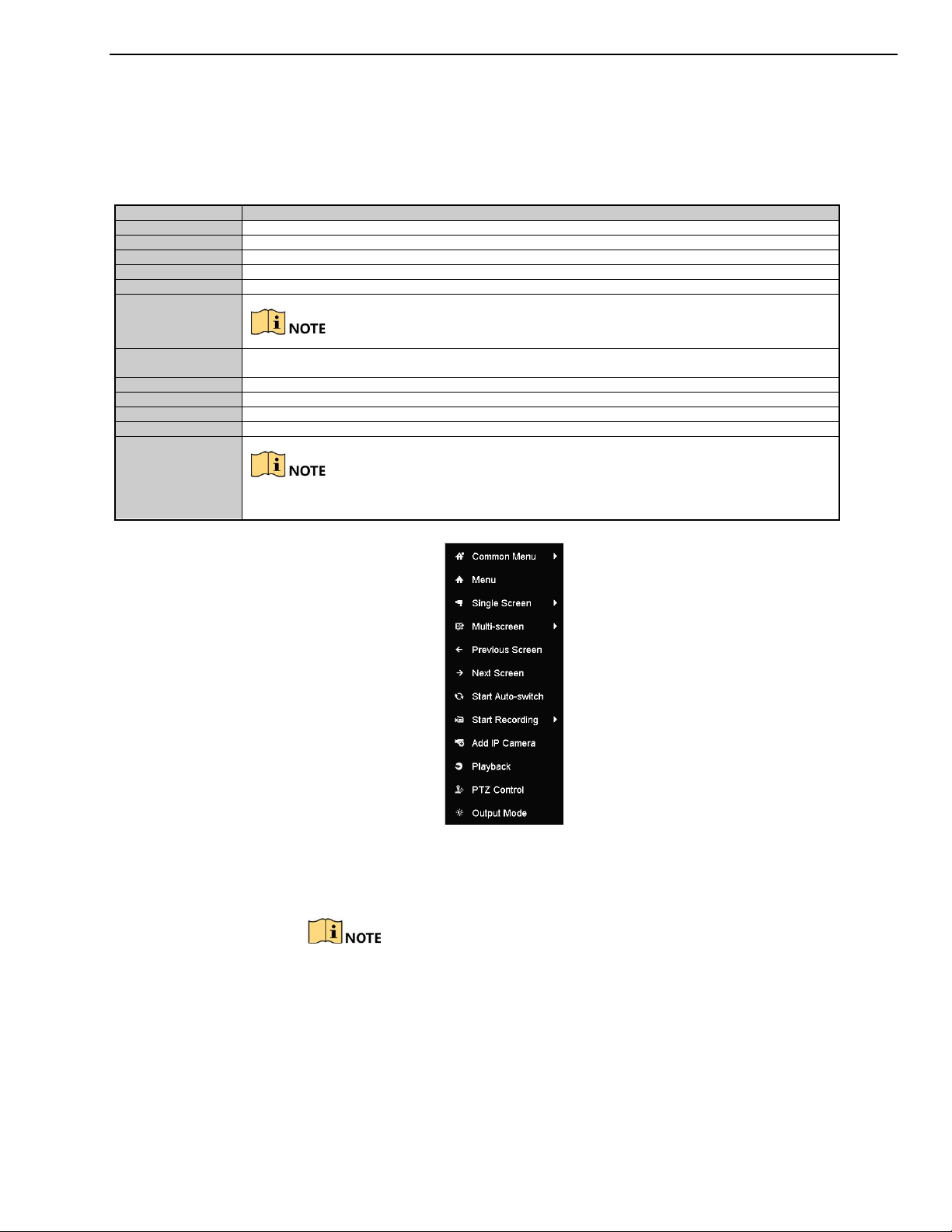
DS-73xxHUI-K4, DS-73xxHQI-K4, DS-90xxHUI-K8 DVR User Manual
Name
Description
Menu
Enter the main menu of the system by right clicking the mouse.
Single Screen
Switch to the single full screen by choosing channel number from the
drop-down
list.
Multi-S
creen
Adjust the screen layou
t by
select
ing from the
drop-down
list.
Previous Screen
Switch to the previous screen.
Next Screen
Switch to the next screen.
Start/Stop
Enable/disable the auto
-
switch of the screens.
The
dwell time
of the live view configuration must be
set before using
Start Auto
-Switch
.
Start Recording
Start recording of all channels,
Continuous
Recor
d,
and Motion Detection Record
are selectable from
the
drop-down
list. Add IP Camera
A shortcut to enter the IP camera management interface.
(For HDVR s
eries only)
Playback
Enter the playback interface and start playing back the video of the selected channel immediately.
PTZ Control
A shortcut to enter the PTZ control interface of the selected camera.
Output Mode
Output Mode is configurable with Standa
rd, Bright, Gentle and Vivid options.
Aux Monitor
Switch to the auxiliary output mode and the operation for the main output is disabled.
button on IR remote control and then press the Enter button.
3.3.1 Using the Mouse in Live View
Refer to Table 1-11 for the description of mouse operation in live view mode.
Table 1-11 Mouse Operation in Live View
Auto-Switch
If you enter Aux monitor mode and the Aux monitor is not connected, the mouse operation is
disabled. You need to switch back to the Main output with the F1 button on front panel or VOIP/MON
Figure 44, Right-click Menu
3.3.2 Switching Main/Aux Output
The CVBS output only serves as the aux output or Live View output.
1. Use the mouse wheel to double-click on the HDMI1/VGA, or HDMI2, or
HDMI/VGA output screen, and the following message box pops up.
UM DS-73xxHUI-K4 DS-73xxHQI-K4 DS-90xxHUI-K8 032918NA 44
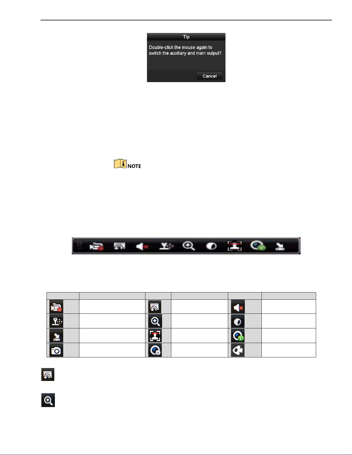
DS-73xxHUI-K4, DS-73xxHQI-K4, DS-90xxHUI-K8 DVR User Manual
Icons
Description
Icons
Description
Icons
Description
Start
/
Stop
Manual
Record
ing
Live View
Strategy
Figure 45, Switch Main and Aux Output
2. Use the mouse wheel to double-click on the screen ag
ain to switch to the
aux output, or click Cancel to cancel the operation.
3. Select the Menu Output Mode to others from the right-click menu on the
monitor.
4. On the pop-up message box, click Yes to reboot the device to enable the
selected menu output as the main output.
You can select the Menu Output Mode under Menu > Configuration >
General > More Settings to Auto, HDMI1/VGA and HDMI2 and then
reboot the device to switch the main output.
3.3.3 Quick Setting Toolbar in Live View Mode
On the screen of each channel, there is a quick setting toolbar that appears
when you click the screen.
Figure 46, Quick Setting Toolbar
Refer to Table below for description of the Quick Setting Toolbar icons.
Table 1-12 Description of Quick Setting Toolbar Icons
Instant Playback
PTZ Control
Close Live View
Digital Zoom
Face Detection
Capture
Audio On/Mute
Image Settings
Information
Fisheye
Instant Playback shows only the record in the last five minutes. If no record is found, it means
there is no record during the last five minutes.
Digital Zoom zooms in the live image. You can zoom in the image to different proportions (1 to
16x) by moving the sliding bar. You can also scroll the mouse wheel to control the zoom in/out.
UM DS-73xxHUI-K4 DS-73xxHQI-K4 DS-90xxHUI-K8 032918NA 45
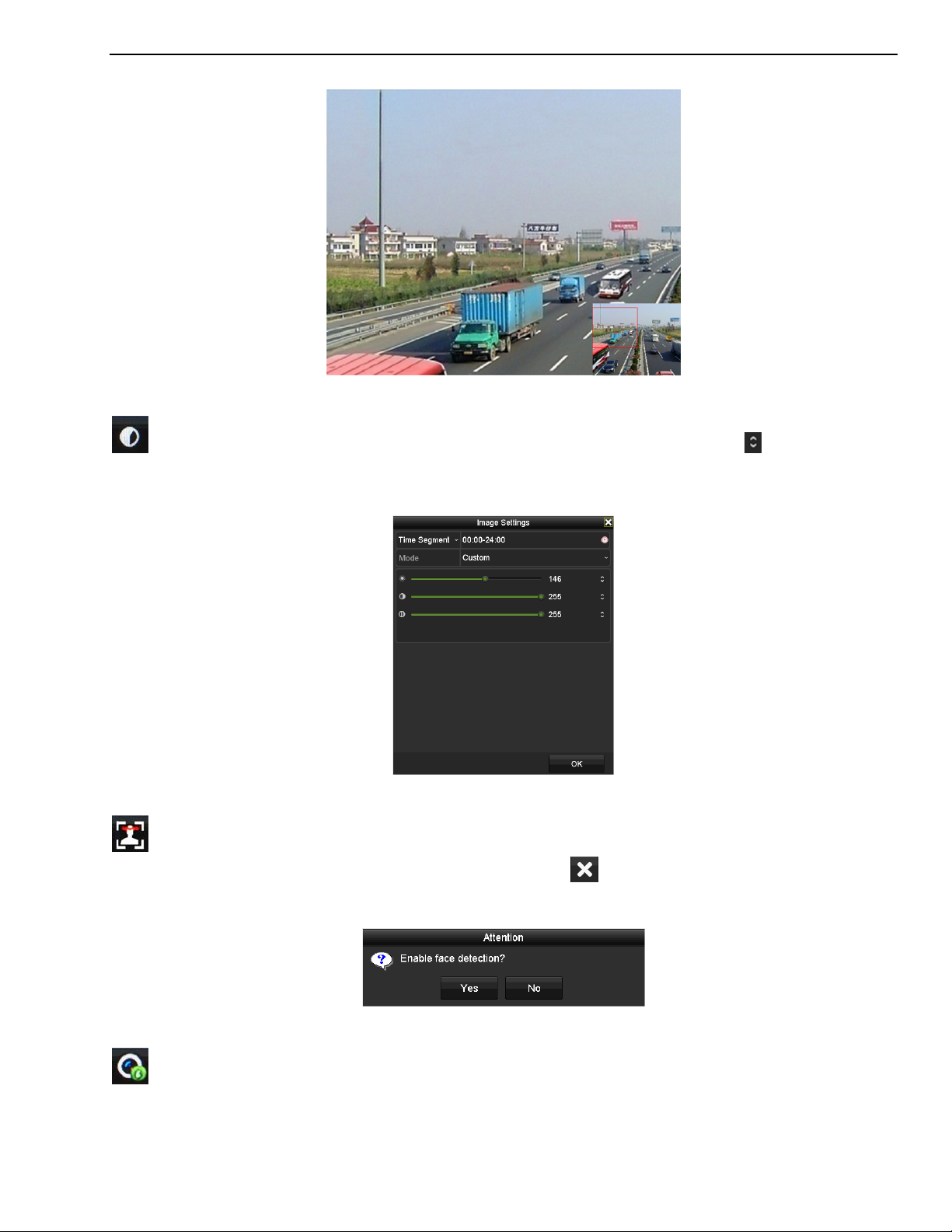
DS-73xxHUI-K4, DS-73xxHQI-K4, DS-90xxHUI-K8 DVR User Manual
Figure 47, Digital Zoom
Image Settings icon enters the Image Settings menu. Drag the mouse or click to adjust the
image parameters, including brightness, contrast, and saturation.
Figure 48, Image Settings
Enable Face Detection by clicking the icon. The dialog pops up as shown in Figure 3-6. Click Yes
and the full-screen live view of the channel is enabled. Click to exit from full-screen mode. You can
configure face detection only when it is supported by the connected camera.
Figure 49, Enable Face Detection
Move the mouse onto the Information icon to show the real-time stream information, including
the frame rate, bit rate, resolution, and stream type.
UM DS-73xxHUI-K4 DS-73xxHQI-K4 DS-90xxHUI-K8 032918NA 46
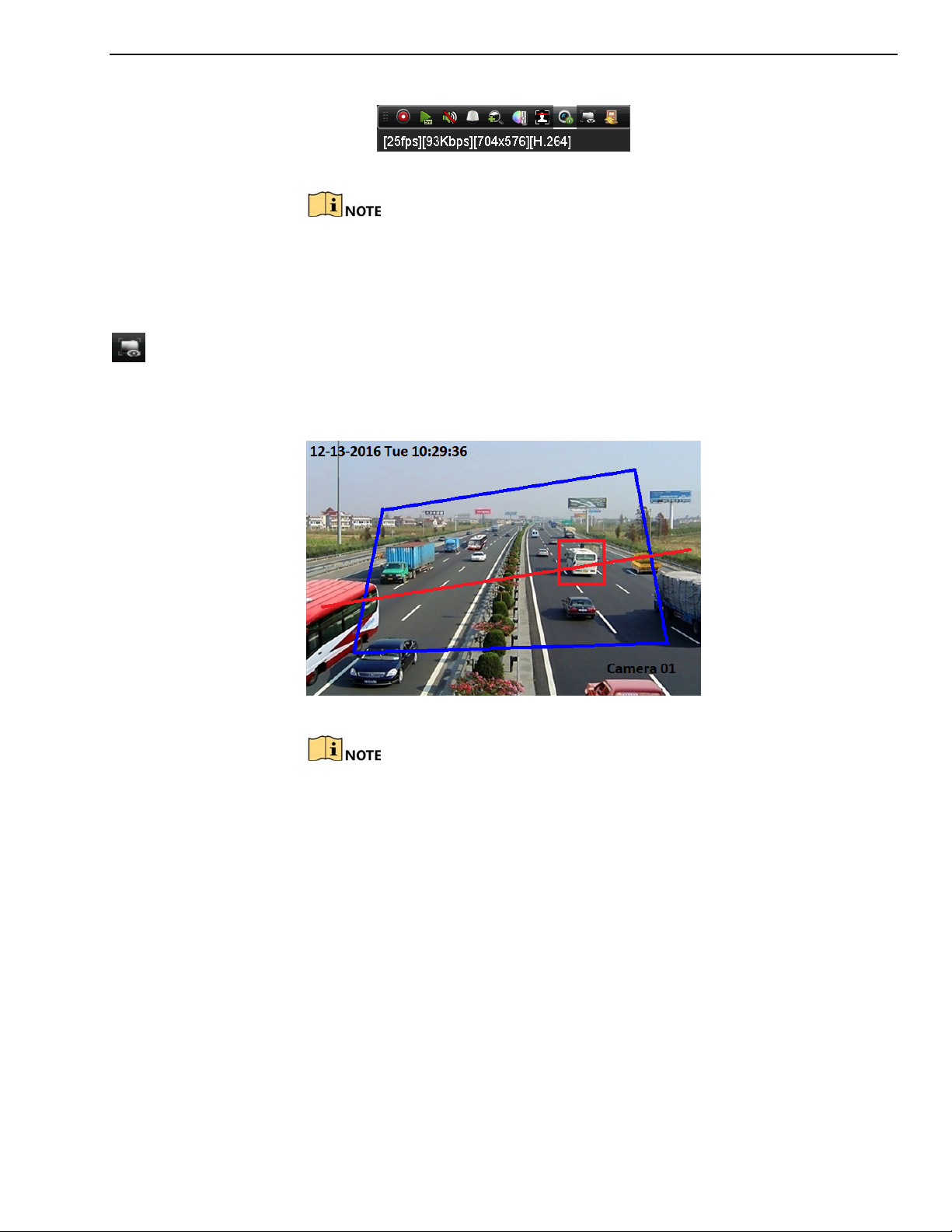
DS-73xxHUI-K4, DS-73xxHQI-K4, DS-90xxHUI-K8 DVR User Manual
Figure 50, Information
When an H.264 IP camera is connected, the stream type is displayed as
H.264. When an IP camera supporting H.264+ is connected, the stream
type is displayed as H.264+. When IP camera supporting H.265 is
connected, the stream type is displayed as H.265. When IP camera
supporting H.265+ is connected, the stream type is displayed as H.265+.
For analog cameras supporting VCA, click the icon to show the VCA information. The configured
line or quadrilateral in the VCA configuration and target frame(s) will be shown on live view. Click the
icon again to hide the VCA information.
Figure 51, Enable VCA Information Overlay
In Live View, only analog cameras support VCA information overlay.
Enable VCA function first before showing the VCA information.
The VCA information is hidden by default. If the connected analog
camera does not support VCA, the icon displays grey and cannot be
operated.
For analog cameras, the VCA information includes line crossing detection
and intrusion detection.
The DVR supports VCA information overlay of only one channel. If you
enable the function of one channel, the other channels will disable the
function automatically.
Both single window and multi-window display modes support VCA
information overlay.
UM DS-73xxHUI-K4 DS-73xxHQI-K4 DS-90xxHUI-K8 032918NA 47
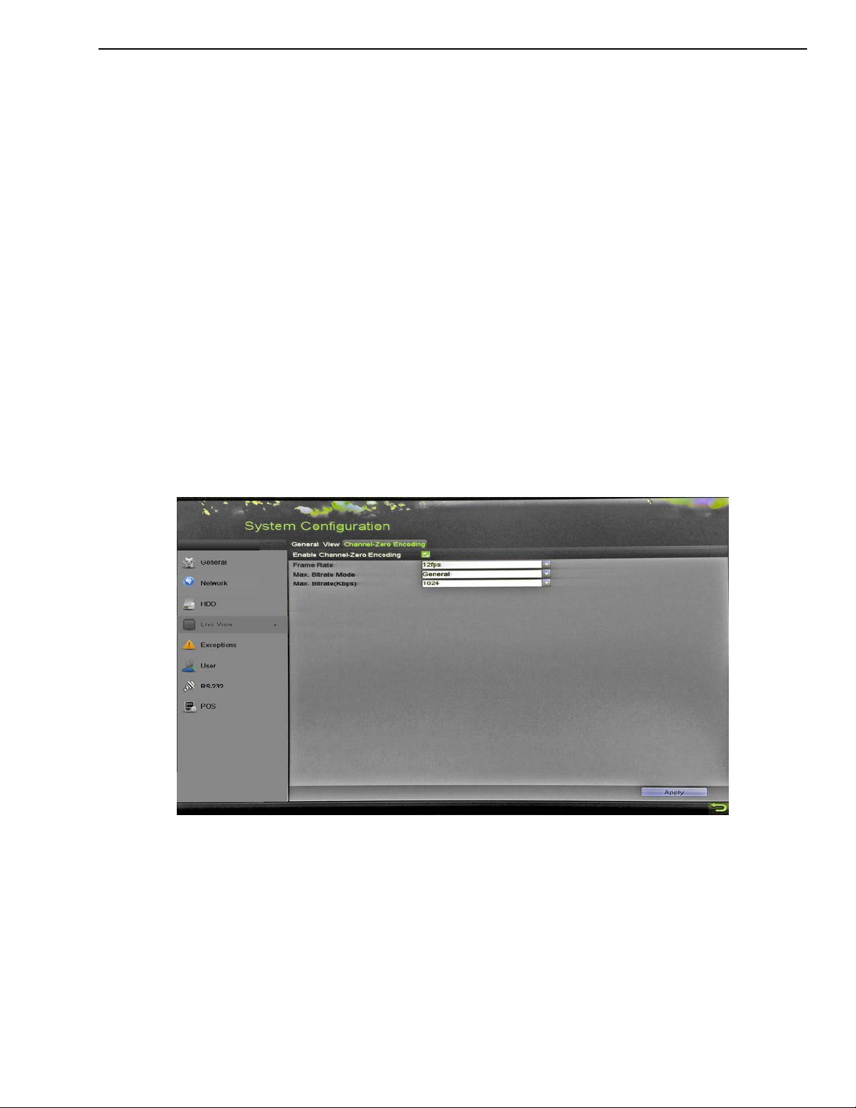
DS-73xxHUI-K4, DS-73xxHQI-K4, DS-90xxHUI-K8 DVR User Manual
Only the main output supports VCA information overlay. When switching
to the aux output, the VCA information overlay of main output is
disabled.
For analog cameras, if the camera number does not exceed the limit for
line crossing detection and intrusion detection, the VCA information
overlay can be enabled for all the analog cameras’ enabled line crossing
detection and intrusion detection. If the camera number exceeds the
limit for line crossing detection, intrusion detection, and sudden scene
change detection, only the cameras’ enabled line crossing detection and
intrusion detection support VCA information overlay. Disabling line
crossing detection and intrusion detection remotely will not affect the
VCA information overlay in the local live view.
3.4 Channel-Zero Encoding
Purpose
Channel-Zero Encoding provides a way to view many channels in real time from a Web
browser or CMS (Client Management System) software by decreasing the bandwidth
requirement without affecting the image quality.
1. Go to Menu > Configuration > Live View > Channel-Zero Encoding.
Figure 52, Live View Channel-Zero Encoding
2. Check the Enable Channel-Zero Encoding checkbox.
3. Configure the Frame Rate, Max. Bitrate Mode, and Max. Bitrate.
4. Click A
5. After you set the Channel-Zero encoding, you can view 16 channels in one screen in the
remote client or Web browser.
UM DS-73xxHUI-K4 DS-73xxHQI-K4 DS-90xxHUI-K8 032918NA 48
pply to activate the settings.

DS-73xxHUI-K4, DS-73xxHQI-K4, DS-90xxHUI-K8 DVR User Manual
3.5 Adjusting Live View Settings
Purpose
Live View settings can be customized. You can configure the output interface, dwell time
for screen to be shown, mute or turn on the audio, the screen number for each channel,
etc.
1. Go to Menu > System Configuration > Live View > Gene
Figure 53, Live View General
ral.
2. The settings available in this menu include:
• Video Output Interface: Selects the output to configure the settings.
3. You can select VGA/HDMI1, HDMI2, Main CVBS for video output interface.
• Live View Mode: Selects the display mode to be used for Live View.
• Dwell Time: The time in seconds to dwell between switching of channels when
enabling auto-switch in Live View.
• Enable Audio Output: Enables/disables audio output for the selected camera in Live
View mode.
• Volume: Adjusts the audio output volume.
• Event Output: Designates the output to show event video. If available, you can select
a different video output interface from the Video Output Interface when an event
occurs.
UM DS-73xxHUI-K4 DS-73xxHQI-K4 DS-90xxHUI-K8 032918NA 49

DS-73xxHUI-K4, DS-73xxHQI-K4, DS-90xxHUI-K8 DVR User Manual
• Full Screen Monitoring Dwell Time: Sets the time in seconds to show the alarm
event screen.
4. Set the camera order.
1) Click the View tab and select V ideo Output Interface from the drop-down list.
Figure 54, Live View Camera Order
2) Click a window to select it, then double-click a camera to display in the camera list.
Setting an ‘X’ means the window will not display any camera.
3) You can also click
live view of all channels. Click or to go to the previous or next page.
4) Click Apply.
to start live view of all channels in order and click to stop
If the sum of the analog and IP channels exceeds 25, up to 32-window division mode
is supported for the VGA/HDMI1 output.
3.6 Manual Video Quality Diagnostics
Purpose
The video quality of the analog channels can be diagnosed manually and you can view the
diagnostic results from a list.
1. Go to Menu > Manual > Manual Video Quality Diagnostics.
Figure 55, Video Quality Diagnostics
UM DS-73xxHUI-K4 DS-73xxHQI-K4 DS-90xxHUI-K8 032918NA 50

DS-73xxHUI-K4, DS-73xxHQI-K4, DS-90xxHUI-K8 DVR User Manual
2. Check the checkboxes to select the channels for diagnostics.
3. Click Diagnose, and the results will be displayed on a list. You can view the video status
and diagnostics time of the selected channels.
Figure 56, Diagnostics Result
Connect the camera to the device for the video quality diagnostics.
Three exception types can be diagnosed: Blurred Image, Abnormal Brightness, and
Color Cast.
4 PTZ Controls
4.1 Configuring PTZ Settings
Purpose
Follow the following procedure to set PTZ parameters. Configure PTZ parameters before
you control the PTZ camera.
1. Go to Menu > Camera > PTZ.
UM DS-73xxHUI-K4 DS-73xxHQI-K4 DS-90xxHUI-K8 032918NA 51

DS-73xxHUI-K4, DS-73xxHQI-K4, DS-90xxHUI-K8 DVR User Manual
Figure 57, PTZ Settings
2. Select the camera for PTZ setting in the Camera drop-down list.
3. Click PTZ Parameters to set the PTZ parameters.
Figure 58, PTZ General
4. Select the parameters of the PTZ camera from the drop-down list.
All the parameters should be exactly the same as the PTZ camera parameters.
For UTC cameras/domes connected, you can select the PTZ protocol to UTC. Make
sure the protocol selected here is supported by the connected camera/dome.
UM DS-73xxHUI-K4 DS-73xxHQI-K4 DS-90xxHUI-K8 032918NA 52

DS-73xxHUI-K4, DS-73xxHQI-K4, DS-90xxHUI-K8 DVR User Manual
When the UTC protocol is selected, all the other parameters such as baud rate, data
bit, stop bit, parity, and flow control are not configurable.
5. (Optional) Click Copy to copy the settings to the other channels. Select the channels
you want to copy to and click OK to return to the PTZ Parameters Settings interface.
Figure 59, Copy to Other Channels
6. Click OK to save the settings.
7. (Optional) Check the Enable Omnicast Control checkbox to enable the PTZ control of
the selected camera via Omnicast VMS of Genetec.
4.2 Setting PTZ Presets, Patrols, and Patterns
Before You Start
Ensure that the presets, patrols, and patterns are supported by PTZ protocols.
4.2.1 Customizing Presets
Purpose
Follow the steps below to set the preset location you want the PTZ camera to
point to when an event occurs.
1. Go to Menu > Camera > PTZ.
UM DS-73xxHUI-K4 DS-73xxHQI-K4 DS-90xxHUI-K8 032918NA 53

DS-73xxHUI-K4, DS-73xxHQI-K4, DS-90xxHUI-K8 DVR User Manual
Figure 60, PTZ Settings
2. Use the directional button to position the camera to the location you
want to set the preset. The zoom and focus operations can be recorded
in the preset as well.
3. Enter the preset No. (1 to 255) in the preset text field, and click Set to link
the location to the preset.
4. Repeat steps 2 and 3 to save more presets.
. Click Clear to clear the location information of the preset, or click Clear
5
All to clear the location information of all presets.
4.2.2 Calling Presets
Purpose
This feature enables the camera to point to a specified position such as a
window when an event takes place.
1. Click PTZ in the lower-right corner of the PTZ setting interface, or press
PTZ on the front panel or click the PTZ Control icon in the quick
setting bar, or select the PTZ option in the right-click menu to show the
PTZ control panel.
2. Choose Ca
3. Click PTZ to show the general settings of the PTZ control.
UM DS-73xxHUI-K4 DS-73xxHQI-K4 DS-90xxHUI-K8 032918NA 54
mera in the drop-down list.

DS-73xxHUI-K4, DS-73xxHQI-K4, DS-90xxHUI-K8 DVR User Manual
Figure 61, PTZ Panel General
4. Click to enter the preset No. in the corresponding text field.
5. Click Call Preset to call it.
When the camera/dome connected and the PTZ protocol is set to UTC,
you can call preset 95 to enter the menu of the connected camera/dome.
Use the directional buttons on the PTZ control panel to operate the
menu.
4.2.3 Customizing Patrols
Purpose
Patrols can be set to move the PTZ camera to different key points and have it
stay there for a set duration before moving on to the next key point. The key
points correspond to the presets. The presets can be set following the steps
above in Customizing Presets.
1. Go to Menu > Camera > PTZ.
UM DS-73xxHUI-K4 DS-73xxHQI-K4 DS-90xxHUI-K8 032918NA 55

DS-73xxHUI-K4, DS-73xxHQI-K4, DS-90xxHUI-K8 DVR User Manual
Figure 62, PTZ Settings
2. Select patrol No. in the Patrol drop-down list.
3. Click Set to add key points to the patrol.
Figure 63, Key point Configuration
4. Configure key point parameters such as the key point No., duration to
stay at one key point, and patrol speed. The key point corresponds to the
preset. The Key Point No. determines the order the PTZ will follow while
cycling through the patrol. Duration refers to the time span to stay at the
corresponding key point. Speed defines the speed the PTZ will move from
one key point to the next.
5. Click Add to add the next key point to the patrol, or click OK to save the
key point to the patrol.
6. You can delete all the key points by clicking Clear for the selected patrol,
or click Clear All to delete all key points for all patrols.
UM DS-73xxHUI-K4 DS-73xxHQI-K4 DS-90xxHUI-K8 032918NA 56

DS-73xxHUI-K4, DS-73xxHQI-K4, DS-90xxHUI-K8 DVR User Manual
4.2.4 Calling Patrols
Purpose
Calling a patrol moves the PTZ according the predefined patrol path.
1. Click PTZ in the lower-right corner of the PTZ Settings interface, or press
PTZ on the front panel or click the PTZ Control icon
setting bar, or select the PTZ option in the right-click menu to show the
PTZ control panel.
2. Click the General tab to show the PTZ controls general settings.
in the quick
Figure 64, PTZ Panel General
3. Select a patrol in the drop-down list and click Call Patrol to call it.
4. You can click Stop Patrol to stop calling it.
4.2.5 Customizing Patterns
Purpose
Patterns can be set by recording the movement of the PTZ. You can call the
pattern to move the PTZ according to the predefined path.
1. Go to Menu > Camera > PTZ.
UM DS-73xxHUI-K4 DS-73xxHQI-K4 DS-90xxHUI-K8 032918NA 57

DS-73xxHUI-K4, DS-73xxHQI-K4, DS-90xxHUI-K8 DVR User Manual
Figure 65, PTZ Settings
2. Choose pattern number in the drop-down list.
3. Click Start and click corresponding buttons in the control panel to move
the PTZ camera. Click Stop to stop movement.
4. The movement of the PTZ is recorded as the pattern.
4.2.6 Calling Patterns
Purpose
Follow the procedure below to move the PTZ camera according to the
predefined patterns.
1. Click PTZ in the lower-right corner of the PTZ Settings interface, or press
PTZ on the front panel, or click the PTZ Control icon in the quick
setting bar, or select the PTZ option in the right-click menu to show the
PTZ control panel.
2. Click the General tab to show the general settings of the PTZ control.
UM DS-73xxHUI-K4 DS-73xxHQI-K4 DS-90xxHUI-K8 032918NA 58

DS-73xxHUI-K4, DS-73xxHQI-K4, DS-90xxHUI-K8 DVR User Manual
Figure 66, PTZ Panel General
3. Click Call Pattern to call it.
4. Click Stop Pattern to stop calling it.
4.2.7 Customizing Linear Scan Limit
Purpose
The Linear Scan can be enabled to trigger the scan in the horizantal direction
in the predefined range.
This function is supported only by certain models.
1. Go to Menu > Camera > PTZ.
UM DS-73xxHUI-K4 DS-73xxHQI-K4 DS-90xxHUI-K8 032918NA 59
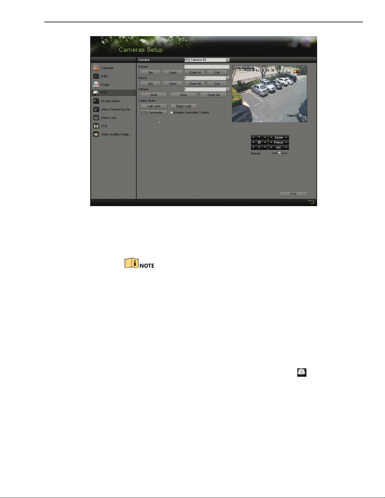
DS-73xxHUI-K4, DS-73xxHQI-K4, DS-90xxHUI-K8 DVR User Manual
Figure 67, PTZ Settings
2. Use the directional button to point the camera to the location you want
to set the limit, and click Left Limit or Right Limit to link the location to
the corresponding limit.
The speed dome starts linear scan from the left limit to the right limit.
You must set the left limit to the left of the right limit, and the angle
from the left limit to the right limit must be no more than 180°.
4.2.8 Calling Linear Scan
Purpose
Follow the following procedure to call the linear scan in the predefined scan
range.
1. Click PTZ in the lower-right corner of the PTZ Settings interface, or press
PTZ on the front panel, or click the PTZ Control icon in the quick
setting bar to enter the PTZ setting menu in live view mode.
2. Click the One-touch tab to show the one-touch function of the PTZ
control.
UM DS-73xxHUI-K4 DS-73xxHQI-K4 DS-90xxHUI-K8 032918NA 60
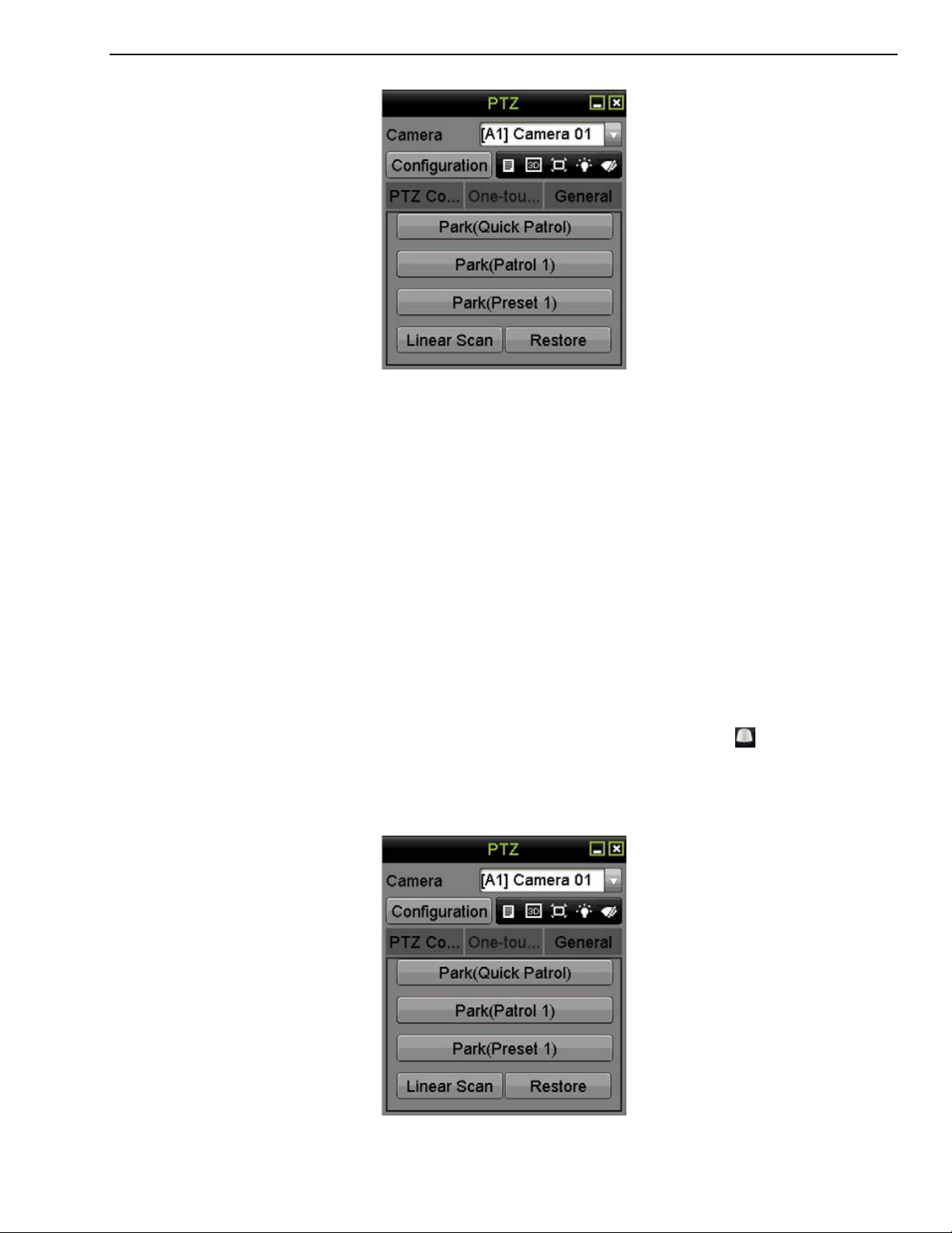
DS-73xxHUI-K4, DS-73xxHQI-K4, DS-90xxHUI-K8 DVR User Manual
Figure 68, PTZ Panel One-Touch
3. Click Linear Scan to start the linear scan and click Linear Scan again to
stop it.
4. You can click Restore to clear the defined left limit and right limit data.
The dome needs to reboot for settings to take effect.
4.2.9 One-Touch Park
Purpose
Certain speed dome models can be configured to start a predefined park
action (scan, preset, patrol, etc.) automatically after a period of inactivity
(park time).
1. Click P
PTZ on the front panel, or click the PTZ Control icon in the quick
setting bar to enter the PTZ setting menu in live view mode.
2. Click the One-touch tab to show the PTZ control’s one-touch function.
TZ in the lower-right corner of the PTZ Settings interface, or press
Figure 69, PTZ Panel One-touch
UM DS-73xxHUI-K4 DS-73xxHQI-K4 DS-90xxHUI-K8 032918NA 61

DS-73xxHUI-K4, DS-73xxHQI-K4, DS-90xxHUI-K8 DVR User Manual
3. There are three one-touch park types selectable. Click the corresponding
button to activate the park action.
4. Park (Quick Patrol): The dome starts the patrol from predefined preset 1
to preset 32 in order after the park time. Any undefined presets will be
skipped.
5. Park (Patrol 1): T
patrol 1 path after the park time.
6. Park (Preset 1): The dome moves to the predefined preset 1 location
after the park time.
The park time can only be set through the speed dome configuration
interface. The default value is 5s.
7. Click the button again to deactivate it.
4.3 PTZ Control Panel
There are two ways to enter the PTZ control panel.
• OPTION 1
In the PTZ Settings interface, click PTZ on the lower-right corner, next to the Back
button.
• OPTION 2
he dome starts moving according to the predefined
n Live View mode, press PTZ Control on the front panel or on the remote control, or
I
choose the PTZ Control icon in the quick setting bar, or select the PTZ Control
option in the right-click menu.
Click Configuration on the control panel.
In PTZ control mode, the PTZ panel will be displayed when a mouse is connected to
the device. If no mouse is connected, the icon appears in the lower-left corner
of the window, indicating that this camera is in PTZ control mode.
UM DS-73xxHUI-K4 DS-73xxHQI-K4 DS-90xxHUI-K8 032918NA 62

DS-73xxHUI-K4, DS-73xxHQI-K4, DS-90xxHUI-K8 DVR User Manual
Direction
button
The PTZ
speed
Switch to the
interface
Figure 70, PTZ Control Panel
Refer to Table 1-13 for description of the PTZ panel icons.
Table 1-13 Description of the PTZ Panel Icons
Icon Description Icon Description Icon Description
button and the
auto-cycle
movement
3D-Zoom
Switch to the
PTZ control
interface
Exit
Zoom+, Focus+,
Iris+
Light on/off
Image
Centralization
one-touch
control
Minimize
windows
5 Recording and Capture Settings
5.1 Configuring Encoding Parameters
1. Make sure that an HDD has been installed. If not, install and initialize an HDD. (Menu >
System Configuration > HDD)
Zoom-, Focus-,
Iris-
Wiper on/off
Menu
Switch to the
general settings
interface
UM DS-73xxHUI-K4 DS-73xxHQI-K4 DS-90xxHUI-K8 032918NA 63

DS-73xxHUI-K4, DS-73xxHQI-K4, DS-90xxHUI-K8 DVR User Manual
Figure 71, HDD
2. Click Advanced tab to check the HDD storage mode (Menu > HDD > Storage Mode).
1) If the HDD mode is Quota, set the maximum record capacity.
2) If the HDD mode is Group, set the HDD group.
Figure 72, HDD – Storage Mode
3. Go to Menu > Record Information > Parameters.
UM DS-73xxHUI-K4 DS-73xxHQI-K4 DS-90xxHUI-K8 032918NA 64

DS-73xxHUI-K4, DS-73xxHQI-K4, DS-90xxHUI-K8 DVR User Manual
Figure 73, Record Parameters
4. Set the recording parameters.
1) Select the Record tab to configure.
2) Select a camera from the camera drop-down list.
3) View the Camera Resolution.
When TurboHD input is connected, you can view the information including the input
signal type, resolution and frame rate (e.g., 5 MP 20 Hz). When CVBS input is
connected, you can view information such as NTSC or PAL.
4) Configure the following parameters for the M
Main Stream (Event).
• Stream Type: Set the stream type to be Video or Video & Audio.
• Resolution: Set recording resolution.
ain Stream (Continuous) and the
HUI Series DVRs support 5 MP and 4 MP resolution on all channels.
The analog signal inputs (TurboHD CVBS) and IP signal input is recognized and connect
automatically.
If the configured encoding resolution conflicts with the resolution of the front-end
camera, the encoding parameters will adjust automatically to meet the front-end
camera. E.g., if the resolution of the front-end camera is 720p, then the encoding
resolution of the main stream will adjust to 720p automatically.
Refer to the Appendix-Specifications for the supported resolutions by model.
• Bitrate Type: S
UM DS-73xxHUI-K4 DS-73xxHQI-K4 DS-90xxHUI-K8 032918NA 65
et the bitrate type to be Variable or Constant.

DS-73xxHUI-K4, DS-73xxHQI-K4, DS-90xxHUI-K8 DVR User Manual
• Video Quality: Set the video quality of recording, with six levels configurable.
The Stream Type, Resolution, Bitrate Type, and Video Quality are not configurable for
the Main Stream (Event) of the IP Camera.
• Frame Rate: Set the frame rate of recording.
For HUI Series DVRs, when a 5 MP signal input is connected, the frame rate of the
main stream cannot exceed 12 fps. When a 4 MP signal input is connected, the frame
rate of the main stream cannot exceed 15 fps.
The minimum frame rate for main stream is 1 fps.
• Max. Bitrate Mode: Set the mode to General or Custom.
• Max Bitrate (Kbps): Select or customize the maximum bit rate for recording.
• Max. Bitrate Range Recommended: A recommended max. bit rate range is
provided for reference.
• Max. Average Bitrate (Kbps): Set the max. average bit rate, which refers to the
average amount of data transferred per unit of time.
• Video Encoding: You can configure H.264 or H.265 for the main stream
(continuous) of IP and analog cameras. Check the Enable H.264+ or Enable
H.265+ checkbox to enable this function. Enabling it helps to ensure high video
quality with a lowered bitrate.
When the connected IP camera does not support H.265, only H.264 can be seleted for
the main stream (continuous).
The analog and IP cameras support enabling H.264+/H.265+ if the video encoding is
H.264/H.265 for the main stream.
After enabling H.264+ or H.265+, the Bitrate Type, Video Quality, Max. Bitrate Mode,
Max. Bitrate (Kbps), and Max. Bitrate Range Recommend are not configurable.
If H.265+ is enabled, line crossing detection and region entrance detection are not
supported.
For a connnected IP camera, H.264+ or H.265+ must be supported by the camera and
added to the DVR with the HIKVISION protocol.
5. Reboot the device to activate the new settings after enabling H.264+ or H.265+.
6. Click More Settings to configure additional parameters.
UM DS-73xxHUI-K4 DS-73xxHQI-K4 DS-90xxHUI-K8 032918NA 66

DS-73xxHUI-K4, DS-73xxHQI-K4, DS-90xxHUI-K8 DVR User Manual
Figure 74, More Settings of Record Parameters (Quota Mode Shown)
• Pre-record: The amount of time to record before the scheduled time or event.
For example, if an alarm triggers recording at 10:00, if the pre-record time is 5
seconds, the camera starts recording at 9:59:55.
• Post-record: The time to record after the event or scheduled time. For example,
if an alarm recording ends at 11:00, if the post-record time is 5 seconds, it
records until 11:00:05.
• Expired Time: The time to keep the record files in the HDDs. Once this time is
exceeded, the files will be deleted. The files will be saved permanently if the
value is set to “0.” The actual retention time for the files should be determined
by the HDDs capacity.
• Redundant Record:
the redundant HDD.
• Record Audio: Enable this feature to record the video with sound and disable it
to record the video without sound.
• Video Stream: Main stream, Sub-stream, and Dual-stream are selectable for
recording. Sub-stream records for a longer time in the same storage space.
Enabling redundant record means records will be saved in
Redundant Record is available only when the HDD mode is Group.
A redundant HDD is required for the redundant record function.
For network cameras, the Main Stream (Event) parameters are not editable.
7. Click Apply to save the settings.
8. Optionally, click Copy to copy the settings to other analog channels if needed.
UM DS-73xxHUI-K4 DS-73xxHQI-K4 DS-90xxHUI-K8 032918NA 67

DS-73xxHUI-K4, DS-73xxHQI-K4, DS-90xxHUI-K8 DVR User Manual
Figure 75, Copy Camera Settings
9. Set encoding parameters for sub-stream.
) Select the Sub-Stream tab.
1
Figure 76, Sub-Stream Encoding
2) Select a camera in the camera drop-down list.
3) Configure the parameters.
) Click Apply to save the settings.
4
5) (Optional) If the parameters can also be used for other cameras, click Copy to copy
the settings to other channels.
The sub-stream resolution can be selected among WD1, 4CIF, and CIF.
The minimum frame rate for the sub-stream is 1 fps.
You can select the Video Encoding for the sub-stream of IP and analog cameras. For
analog cameras, H.264 and H.265 are selectable. For IP cameras supporting H.265,
you can select H.265 encoding mode.
10. Set parameters for capture.
1) Select the C
UM DS-73xxHUI-K4 DS-73xxHQI-K4 DS-90xxHUI-K8 032918NA 68
apture tab.

DS-73xxHUI-K4, DS-73xxHQI-K4, DS-90xxHUI-K8 DVR User Manual
Figure 77, Capture Settings
2) Select a camera from the drop-down list.
3) Configure the parameters.
4) Click Apply to save the settings.
5) (Optional) If the parameters can also be used for other cameras, click Copy to copy
the settings to other channels.
The interval is the time period between two capturing actions. You can configure all
the parameters on this menu upon demand.
5.2 Configuring Recording and Capture Schedule
The DVR supports continuous, alarm, motion, motion | alarm, motion & alarm, event,
and POS triggered recording types.
In this chapter, the record schedule procedure is used as an example, and the same
procedure can be applied to configure a recording schedule.
Purpose
Set the record schedule, then the camera will automatically start/stop recording according
to the configured schedule.
1. Go to Menu > Record/Capture > Schedule.
UM DS-73xxHUI-K4 DS-73xxHQI-K4 DS-90xxHUI-K8 032918NA 69

DS-73xxHUI-K4, DS-73xxHQI-K4, DS-90xxHUI-K8 DVR User Manual
Figure 78, Record Schedule
Different recording types are marked in different color icons.
• Continuous: Scheduled recording
• Event: Recording triggered by any event triggered alarm
• VCA: Recording triggered by a VCA event
• None: No scheduled recording
2. Choose the camera you want to configure in the Camera drop-down list.
3. Check the Enable Schedule checkbox.
4. Configure the record schedule.
. Edit the schedule
5
1) Click Edit.
2) Choose the day you want to set the schedule in the message box.
3) To schedule all-day recording, check the All Day item checkbox.
Figure 79, Edit Schedule – All Day
UM DS-73xxHUI-K4 DS-73xxHQI-K4 DS-90xxHUI-K8 032918NA 70

DS-73xxHUI-K4, DS-73xxHQI-K4, DS-90xxHUI-K8 DVR User Manual
4) To arrange other schedules, leave the 24HR checkbox blank and set the Start/End
time.
Figure 80, Edit Schedule – Set Time Period
Up to eight periods can be configured for each day. Time periods cannot overlap each
other.
To enable Event, Motion, Alarm, M | A (motion or alarm), M & A (motion and alarm),
and POS triggered recording, you must configure the motion detection settings, alarm
input settings or VCA settings as well.
5) Repeat the above steps 1 to 4 to schedule recordings for other days in the week. If
the schedule can also be set for other days, click Copy.
Figure 81, Copy Schedule to Other Days
The Holiday option is available when you enable holiday schedule in Holiday settings.
6) Click OK to save the settings and return to the upper level menu.
6. Draw the schedule
1) Click the color icon to select a record type in the event list on the right side of the
interface.
UM DS-73xxHUI-K4 DS-73xxHQI-K4 DS-90xxHUI-K8 032918NA 71

DS-73xxHUI-K4, DS-73xxHQI-K4, DS-90xxHUI-K8 DVR User Manual
Figure 82, Draw the Recording Schedule
Figure 83, Draw the Capture Schedule
2) Drag the mouse on the schedule.
3) Click an area outside of the schedule table to finish and exit from the drawing.
UM DS-73xxHUI-K4 DS-73xxHQI-K4 DS-90xxHUI-K8 032918NA 72

DS-73xxHUI-K4, DS-73xxHQI-K4, DS-90xxHUI-K8 DVR User Manual
Repeat to set schedule other channels. If the settings can also be used for other
channels, click Copy, and then choose the channel you want to copy to.
7. Click Apply in the Record Schedule interface to save the settings.
5.3 Configuring Motion Detection Recording and Capture
Purpose
Follow these steps to set the motion detection parameters. In Live View mode, once a
motion detection event takes place, the DVR can analyze it and perform many actions to
handle it. Enabling the motion detection function can trigger certain channels to start
recording, or trigger full screen monitoring, audio warning, notifying the surveillance center,
sending e-mail, and so on.
1. Go to Menu > Camera > Motion.
Figure 84, Motion Detection
2. Configure Motion Detection:
1) Choose camera you want to configure.
2) Check the Enable Motion Detection checkbox.
3) Use the mouse to drag and draw the area for motion detection. To set the motion
detection for the entire area shot by the camera, click Full Screen. To clear the
motion detection area, click Clear.
UM DS-73xxHUI-K4 DS-73xxHQI-K4 DS-90xxHUI-K8 032918NA 73

DS-73xxHUI-K4, DS-73xxHQI-K4, DS-90xxHUI-K8 DVR User Manual
Figure 85, Motion Detection – Mask
4) Click Set, and the channel information message box pops up.
Figure 86, Motion Detection Settings
5) Select the channels that you want the motion detection event to trigger recording.
6) Click Apply to save the settings.
7) Click OK to return to the upper level menu.
8) Exit the Motion Detection menu.
3. Configure the schedule.
4. Choose Motion as the record type.
5.4 Configuring Alarm Triggered Recording and Capture
Purpose
Follow the procedure to configure alarm triggered recording or capture.
1. Go to Menu > Recording Configuration > Trigger > Ala
UM DS-73xxHUI-K4 DS-73xxHQI-K4 DS-90xxHUI-K8 032918NA 74
rm Input.

DS-73xxHUI-K4, DS-73xxHQI-K4, DS-90xxHUI-K8 DVR User Manual
Figure 87, Alarm Settings – Alarm Input
2. Select Alarm Input No.
3. Input Alarm Name.
4. Select N.O. (normally open) or N.C. (normally closed) for alarm type.
5. Check the Enable checkbox to enable alarm.
6. Click S
et to set the triggered channels, arming schedule, linkage actions, and PTZ
linking.
Figure 88, Alarm Handling
7. Click Apply to save the settings.
8. Repeat steps 1 to 8 to configure other alarm input p
arameters.
9. If the settings can also be applied to other alarm inputs, click Copy and choose the
alarm input number.
UM DS-73xxHUI-K4 DS-73xxHQI-K4 DS-90xxHUI-K8 032918NA 75

DS-73xxHUI-K4, DS-73xxHQI-K4, DS-90xxHUI-K8 DVR User Manual
Figure 89, Copy Alarm Input
5.5 Configuring Event Recording and Capture
Purpose
Event triggered recording can be configured through the menu. The events include motion
detection, alarms, and VCA events (face detection/face capture, line crossing detection,
intrusion detection, region entrance detection, region exiting detection, loitering detection,
people gathering detection, fast moving detection, parking detection, unattended baggage
detection, object removal detection, audio loss exception detection, sudden change of
sound intensity detection, and defocus detection).
The HUI Series supports line crossing detection and intrusion detection of all channels,
and 2-ch sudden scene change detection. Channels with audio support audio
exception detection.
For analog channels, the line crossing detection and intrusion detection conflict with
other VCA detection such as sudden scene change detection, face detection, and
vehicle detection. You can enable only one function.
1. Go to Menu > Camera > VCA.
Figure 90, VCA Settings
UM DS-73xxHUI-K4 DS-73xxHQI-K4 DS-90xxHUI-K8 032918NA 76

DS-73xxHUI-K4, DS-73xxHQI-K4, DS-90xxHUI-K8 DVR User Manual
2. Select a Camera.
3. Configure the detection rules for VCA events.
4. Click Set to configure the alarm linkage actions for the VCA events.
5. Select Trigger Channel tab and select one or more channels that will start to record
when a VCA alarm is triggered.
6. Click A
7. Enter Record Schedule Settings interface (Menu > Record > Schedule > Record
Schedule) and set Event as the record type.
pply to save the settings.
Figure 91, Set Triggered Camera of VCA Alarm
5.6 Configuring Manual Recording and Continous Capture
Purpose
Follow these steps to set parameters for manual recording and continuous capture. Using
manual recording and continuous capture, you need to manually cancel the record and
capture. The manual recording and manual continuous capture is prior to the scheduled
recording and capture.
1. Go to Menu > Manual > Record.
Figure 92, Manual Record
2. Enable manual record.
UM DS-73xxHUI-K4 DS-73xxHQI-K4 DS-90xxHUI-K8 032918NA 77

DS-73xxHUI-K4, DS-73xxHQI-K4, DS-90xxHUI-K8 DVR User Manual
3. Click the status icon before the camera number to change it to , or click Analog
to enable manual record of all channels.
4. Disable manual record.
5. Click to change it to , or click Analog to disable manual record of all
channels.
After rebooting all the manual records enabled are canceled.
5.7 Configuring Holiday Recording and Capture
Purpose
Follow these steps to configure the record or capture holiday schedules for the year to have
different recording plans on holidays.
1. Go to Menu > Recording Configuration > Holiday.
Figure 93, Holiday Settings
2. Enable Edit Holiday schedule.
1) Click to enter the Edit interface.
UM DS-73xxHUI-K4 DS-73xxHQI-K4 DS-90xxHUI-K8 032918NA 78

DS-73xxHUI-K4, DS-73xxHQI-K4, DS-90xxHUI-K8 DVR User Manual
Figure 94, Edit Holiday Settings
2) Check the Enable checkbox.
3) Select Mode from the drop-down list (by Month, By Week, and By Date are
selectable).
3. Set the start and end date.
4. Click A
pply to save settings.
5. Click OK to exit the Edit interface.
6. Go to Menu > Recording Configuration > Schedule.
7. Click on Edit.
8. Choose Holiday in the Schedule drop-down list or draw the schedule on the Holiday
timeline.
UM DS-73xxHUI-K4 DS-73xxHQI-K4 DS-90xxHUI-K8 032918NA 79

DS-73xxHUI-K4, DS-73xxHQI-K4, DS-90xxHUI-K8 DVR User Manual
Figure 95, Edit Schedule – Holiday
Up to eight periods can be configured for each day. Time periods cannot overlap each
other.
In the channel time table, both holiday schedule and normal day schedule are
displayed.
Repeat step 4 to set Holiday schedules for other channels. If the holiday schedule can
be used for other channels, click Copy and choose the channel you want to apply the
settings.
5.8 Configuring Redundant Recording and Capture
Purpose
Enabling redundant recording and capture saves the record files and captured pictures not
only in the R/W HDD but also in the redundant HDD, to effectively enhance data safety and
reliability.
Before You Start
Set the Storage mode in the HDD advanced settings to Group before setting the HDD
property to Redundant. There must be at least one other HDD in Read/Write status.
1. Go to Menu > System Configuration > HDD.
UM DS-73xxHUI-K4 DS-73xxHQI-K4 DS-90xxHUI-K8 032918NA 80

DS-73xxHUI-K4, DS-73xxHQI-K4, DS-90xxHUI-K8 DVR User Manual
Figure 96, HDD Information
2. Select the HDD and click to enter the Local HDD Settings interface.
1) Set the HDD property to Redundant.
Figure 97, HDD General – Editing
2) Click Apply to save the settings.
3) Click OK to return to the upper level menu.
3. Go to Menu > Record > Parameters > Record.
1) Select the Camera you want to configure.
2) Click More Settings.
UM DS-73xxHUI-K4 DS-73xxHQI-K4 DS-90xxHUI-K8 032918NA 81

DS-73xxHUI-K4, DS-73xxHQI-K4, DS-90xxHUI-K8 DVR User Manual
Figure 98, More Settings
3) Check the Redundant Record checkbox.
4) Click OK to save the settings.
5) If the encoding parameters can also be used for other channels, click Copy and
choose the channel you want to apply the settings.
5.9 Configuring HDD Group
Purpose
You can group the HDDs and save the record files in a certain HDD group.
1. Go to Menu > HDD > Advanced > Storage Mode.
. Check whether the storage mode of the HDD is Group. If not, set it to Group.
2
3. Select General in the left bar.
4. Click to enter editing interface.
5. Configuring HDD group.
1) Choose a group number for the HDD group.
2) Click Apply to save your settings.
3) Click OK to return to the upper level menu.
6. Repeat the above steps to configure more HDD groups.
7. Choose the Channels that you want to save the record files in the HDD group.
1) Go to Menu > HDD > Advanced > Storage Mode.
UM DS-73xxHUI-K4 DS-73xxHQI-K4 DS-90xxHUI-K8 032918NA 82

DS-73xxHUI-K4, DS-73xxHQI-K4, DS-90xxHUI-K8 DVR User Manual
Figure 99, HDD Advanced
2) Choose Group number in the drop-down list of Record on HDD Group
3) Check the channels you want to save in this group.
) Click Apply to save settings.
4
After you have configured the HDD groups, configure the recording settings.
5.10 Files Protection
Purpose
You can lock the recorded files or set the HDD property to Read-only to protect the record
files from being overwritten.
5.10.1 Protect Record Files by Locking Them
• Go to Menu > File Management.
Figure 100, Export
• Select the channels you want to investigate by checking the
checkbox.
• Configure the record mode, record type, file type, s
time.
• Click Search to show the results.
UM DS-73xxHUI-K4 DS-73xxHQI-K4 DS-90xxHUI-K8 032918NA 83
tart time, and end

DS-73xxHUI-K4, DS-73xxHQI-K4, DS-90xxHUI-K8 DVR User Manual
Figure 101, Export – Search Result
• Protect the record files.
1) Find the record files you want to protect, then click , which will
turn to a , indicating that the file is locked.
Record file recordings not completed cannot be locked.
2) Click to change it to to unlock and unprotect the file.
5.10.2 Protect File by Setting HDD to Read-Only
Before You Start
To edit the HDD property, set the HDD storage mode to Group.
1. Go to Menu > HDD > General.
Figure 102, HDD General
2. Click to edit the HDD you want to protect.
UM DS-73xxHUI-K4 DS-73xxHQI-K4 DS-90xxHUI-K8 032918NA 84

DS-73xxHUI-K4, DS-73xxHQI-K4, DS-90xxHUI-K8 DVR User Manual
Figure 103, HDD General – Editing
3. Set the HDD to Read-only.
4. Click OK to save settings and return to the upper level menu.
You cannot save files to a read-only HDD. If you want to save files to the
HDD, change the property to R/W.
If there is only one HDD and it is set to read-only, the DVR cannot record
any files. Only live view mode is available.
If you set the HDD to read-only when the DVR is saving files in it, the file
will be saved to the next R/W HDD. If there is only one HDD, the
recording will be stopped.
5.11 One-Key Enable/Disable H.264+/H.265+, Analog Cameras
Purpose
You can one-key enable or disable H.264+/H.265+ for analog cameras.
5.11.1 Enabling
1. Go to Menu > Record > Advanced.
Figure 104, Advanced Settings
2. Click E
following attention box pops up.
UM DS-73xxHUI-K4 DS-73xxHQI-K4 DS-90xxHUI-K8 032918NA 85
nable to enable H.264+/H.265+ for all the analog cameras and the

DS-73xxHUI-K4, DS-73xxHQI-K4, DS-90xxHUI-K8 DVR User Manual
Figure 105, Attention Box
3. Click Yes to enable the function and reboot the device for new settings to
take effect.
5.11.2 Disabling
1. Go to Menu > Record > Advanced.
2. Click Disable to disable H.264+ for all the analog cameras and the
following attention box pops up.
5.12 Playback
5.12.1 Instant Playback by Channel
Figure 106, Attention Box
3. Click Yes to enable the function and reboot the device to have new
settings take effect.
Purpose
Play back the recorded video files of a specific channel in Live View mode.
Channel switch is supported.
1. Choose a channel in Live View mode and click in the quick setting
toolbar.
In instant playback mode, only files recorded during the last five minutes
on this channel will be played back.
UM DS-73xxHUI-K4 DS-73xxHQI-K4 DS-90xxHUI-K8 032918NA 86

DS-73xxHUI-K4, DS-73xxHQI-K4, DS-90xxHUI-K8 DVR User Manual
Figure 107, Instant Playback Interface
5.12.2 Playback by Normal Search
5.12.2.1 Playback by Channel
1. Enter the Playback interface.
2. Right click a channel in Live View mode and select Playback
from the menu, as shown below:
Figure 108, Right-click Menu under Live View
UM DS-73xxHUI-K4 DS-73xxHQI-K4 DS-90xxHUI-K8 032918NA 87

DS-73xxHUI-K4, DS-73xxHQI-K4, DS-90xxHUI-K8 DVR User Manual
5.12.2.2 Playback by Time
Purpose
Play back video files recorded during a specified time duration.
Multi-channel simultaneous playback and channel switch are
supported.
1. Go to Menu > Playback.
. Check the checkbox of the channel(s) in the channel list, then
2
double-click to select a date on the calendar.
Figure 109, Playback Calendar
If there are record files for that camera on that day, the icon
for that day is displayed on the calendar as . Otherwise it is
displayed as .
5.12.3 Playback Interface
1. You can select main stream or sub-stream from the playback drop-down
list. You can also use the toolbar in the bottom part of Playback interface
to control playing progress, as shown in the following figure.
Figure 110, Playback Interface
UM DS-73xxHUI-K4 DS-73xxHQI-K4 DS-90xxHUI-K8 032918NA 88

DS-73xxHUI-K4, DS-73xxHQI-K4, DS-90xxHUI-K8 DVR User Manual
Button
Operation
Button
Operation
Button
Operation
File manage
ment for
and tags
Reverse
play/
Pause
Scaling up/down the
time line
Enable/Disable POS
information overlay
2. Select the channel(s) if you want to switch playback to another channel
or execute simultaneous playback of multiple channels.
Figure 111, Playback Toolbar
Table 1-14 Detailed Explanation of Playback Toolbar
/
/
Audio on/Mute
Add default tag
30s forward
Fast forward
Full Screen
Save the clips
Capture Picture
the record files.
represents normal recording (manual or schedule), represents
event recording (motion, alarm, motion | alarm, motion & alarm).
Playback progress bar: use the mouse to click any point of the progress
bar to locate specific frames.
/
Start/Stop clipping
Add customized tag
Stop
30s reverse
Previous day
Exit
Process bar
Lock File
/
/
video clips, captured
pictures, locked files
Digital Zoom
Pause/Play
Slow forward
Next day
indicates the start time and end time of
When POS is enabled when playing back, the POS information will be
overlaid on the video. Keyword searching is supported.
5.12.4 Playback by Event Search
Purpose
Play back record files on one or several channels searched by restricting event
type (motion detection, alarm input, or VCA). Channel switch is supported.
1. Go to Menu > Playback.
. Click and select to enter the Event Playback
2
interface.
UM DS-73xxHUI-K4 DS-73xxHQI-K4 DS-90xxHUI-K8 032918NA 89

DS-73xxHUI-K4, DS-73xxHQI-K4, DS-90xxHUI-K8 DVR User Manual
3. Select Alarm Input, Motion, VCA as the event type, and specify the start
time and end time for search.
Figure 112, Video Search by Motion Detection
4. Click Search, and the record files matching the search conditions will be
listed.
5. Select and click to play back the record files.
6. You can click Back to return to the search interface.
7. If there is only one channel triggered, clicking
Full-screen Playback interface of this channel.
8. If several channels are triggered, clicking takes you to the
Synchronous Playback interface. Check to select one channel for
playback or select multiple channels for synchronous playback.
takes you to
The maximum synchronous playback channels varies by model.
UM DS-73xxHUI-K4 DS-73xxHQI-K4 DS-90xxHUI-K8 032918NA 90

DS-73xxHUI-K4, DS-73xxHQI-K4, DS-90xxHUI-K8 DVR User Manual
Figure 113, Select Channels for Synchronous Playback
9. On the Event Playback interface, select the main stream or sub-stream
from the drop-down list for playback. The toolbar in the bottom part of
the Playback interface can be used to control the playing process.
Figure 114, Interface of Playback by Event
10. Pre-play and post-play can be configured for playback of event triggered
record files.
• Pre-play:
The time to play back before the event. For example, if an
alarm triggered the recording at 10:00, if the pre-play time is five
seconds, the video starts playback from 9:59:55.
UM DS-73xxHUI-K4 DS-73xxHQI-K4 DS-90xxHUI-K8 032918NA 91

DS-73xxHUI-K4, DS-73xxHQI-K4, DS-90xxHUI-K8 DVR User Manual
• Post-play: The time to play back after the event. For example, if an
alarm triggered the recording end at 11:00, if the post-play time is
five seconds, the video plays back until 11:00:05.
11. Click or to select the previous or next event.
5.12.5 Playback by Tag
Purpose
Video tags allow you to record related information such as people and
locations at a certain time point during playback. You can also to use video
tag(s) to search for record files and position the time point.
Before Playing Back by Tag
1. Go to Menu > Playback.
2. Search and play back the record file(s).
Figure 115, Interface of Playback by Time
3. Click to add a default tag.
4. Click
UM DS-73xxHUI-K4 DS-73xxHQI-K4 DS-90xxHUI-K8 032918NA 92
to add a customized tag and input the tag name.

DS-73xxHUI-K4, DS-73xxHQI-K4, DS-90xxHUI-K8 DVR User Manual
Figure 116, Add Tag
A maximum of 64 tags can be added to a single video file.
5. Click to check, edit, and delete tag(s).
Figure 117, Tag Management Interface
1) Select Tag from the drop-down list in the Playback interface.
2) Choose channels, edit start time and end time, then click Search to
enter the Search Result interface.
Enter a keyword into the Keyword textbox to search a tag on command.
UM DS-73xxHUI-K4 DS-73xxHQI-K4 DS-90xxHUI-K8 032918NA 93

DS-73xxHUI-K4, DS-73xxHQI-K4, DS-90xxHUI-K8 DVR User Manual
Figure 118, Video Search by Tag
6. Click to play back the file.
7. Click B
ack to return to the search interface.
Pre-play and post-play can be configured.
Click or to select the previous or next tag.
5.12.6 Playback by Smart Search
Purpose
The Smart Playback provides an easy way to speed through less relevant
information. In Smart Playback mode, the system will analyze the video
containing the motion or VCA information, mark it in green, and play it at
normal speed while video without motion will be played at 16 times speed.
The Smart Playback rules and areas are configurable.
Before You Start
To get the Smart Search result, the corresponding event type must be
enabled and configured on the IP camera. Here we take intrusion detection
as an example.
1. Log into the IP camera via a Web browser, and enable
by checking the checkbox. You may enter the motion detection
UM DS-73xxHUI-K4 DS-73xxHQI-K4 DS-90xxHUI-K8 032918NA 94
intrusion detection

DS-73xxHUI-K4, DS-73xxHQI-K4, DS-90xxHUI-K8 DVR User Manual
configuration interface at Configuration > Advanced Configuration >
Events > Intrusion Detection.
Figure 119, Setting Intrusion Detection on IP Camera
2. Configure the required intrusion detection parameter
s, including area,
arming schedule, and linkage methods. Refer to the Smart IP Camera user
manual for detailed instructions.
1) Go to Menu > Playback.
2) Select Smart in the drop-down list on the top-left side.
3) Select a camera in the camera list.
Figure 120, Smart Playback Interface
4) Select a date in the calendar and click to play.
UM DS-73xxHUI-K4 DS-73xxHQI-K4 DS-90xxHUI-K8 032918NA 95

DS-73xxHUI-K4, DS-73xxHQI-K4, DS-90xxHUI-K8 DVR User Manual
Button
Operation
Button
Operation
Button
Operation
Draw line
for the
detection
Draw quadrilateral
detection
Draw rectangle for
detection
Set full screen for
motion detection
File management
for video clips
Pause playing
/
Play
Filter video files
target characters
S
how/Hide VCA
information
Table 1-15 Detailed Explanation of Smart Playback Toolbar
/
line crossing
Smart settings
for the intrusion
Clear all
Stop playing
Search matched
video files
/
the intrusion
Start/Stop clipping
/
by setting the
5) Set the Smart Search rules and areas for VCA event or motion event.
• Line Crossing Detection: Select , and click on the image to
specify the start point and end point of the line.
• Intrusion Detection: Click , and specify four points to set a
quadrilateral region for intrusion detection. Only one region can
be set.
• Motion Detection: Click and then click and draw the mouse
to set the detection area manually. You can also click to set
the full screen as the detection area.
6) Click
to configure the Smart settings.
Figure 121, Smart Settings
• Skip the Non-Related Video: Non-related video will not be played
if this function is enabled.
• Play Non-Related Video at: S
et the speed to play the non-related
video. Maximum 8/4/2/1 are selectable.
UM DS-73xxHUI-K4 DS-73xxHQI-K4 DS-90xxHUI-K8 032918NA 96
• Play Related Video at: Set the speed to play the related video.
Maximum 8/4/2/1 are selectable.
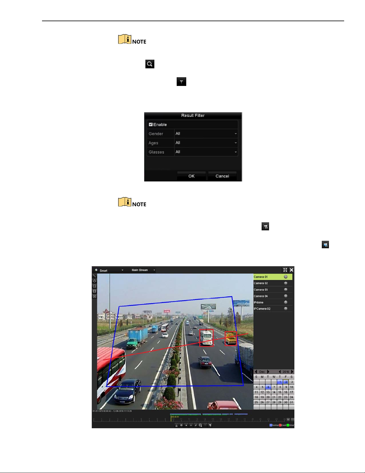
DS-73xxHUI-K4, DS-73xxHQI-K4, DS-90xxHUI-K8 DVR User Manual
Pre-play and post-play is not available for the motion event type.
3. Click to search and play the matched video files.
4. (Optional) Click to filter the searched video files by setting the target
characters, including the gender and age of the human and whether
he/she wears glasses.
Figure 122, Set Result Filter
The Result Filter function is supported by IP cameras only.
5. (Optional) For cameras supporting VCA, click to show the VCA
information. The configured line or quadrilateral in VCA configuration
and target frame(s) will be shown on the playback interface. Click to
hide the VCA information.
Figure 123, Show VCA Information
UM DS-73xxHUI-K4 DS-73xxHQI-K4 DS-90xxHUI-K8 032918NA 97

DS-73xxHUI-K4, DS-73xxHQI-K4, DS-90xxHUI-K8 DVR User Manual
In smart playback, both the analog and IP cameras support VCA
information overlay.
If the connected camera does not support VCA, the icon is grey and
unavailable.
For analog cameras, the VCA information includes line crossing detection
and intrusion detection. For IP cameras, the VCA information includes all
the VCA detections of smart IP camera.
5.12.7 Playback by System Logs
Purpose
Play back record file(s) associated with channels after searching system logs.
1. Go to Menu > Maintenance > System Logs.
Figure 124, System Log Search Interface
2. Set search time and type and Search.
UM DS-73xxHUI-K4 DS-73xxHQI-K4 DS-90xxHUI-K8 032918NA 98

DS-73xxHUI-K4, DS-73xxHQI-K4, DS-90xxHUI-K8 DVR User Manual
Figure 125, Result of System Log Search
3. Choose a log with record file and click to enter Playback interface.
If there is no record file at the time point of the log, “No result found”
will pop up.
4. The toolbar in the bottom part of Playback interface can be used to
control playing process.
Figure 126, Interface of Playback by Log
5.12.8 Playback by Sub-Periods
Purpose
The video files can be played in multiple sub-periods simultaneously.
1. Go to Menu > Playback.
2. Select S
the page to enter the Sub-periods Playback interface.
3. Select a date and start playing the video file.
UM DS-73xxHUI-K4 DS-73xxHQI-K4 DS-90xxHUI-K8 032918NA 99
ub-periods from the drop-down list in the upper-left corner of

DS-73xxHUI-K4, DS-73xxHQI-K4, DS-90xxHUI-K8 DVR User Manual
4. Select the Split-screen Number from the drop-down list. Up to 16 screens
are configurable.
Figure 127, Interface of Sub-periods Playback
According to the defined number of split-screens, the video files on the
selected date can be divided into average segments for playback. E.g., if
there are video files existing between 16:00 and 22:00, and the 6-screen
display mode is selected, then it can play the video files for 1 hour on
each screen simultaneously.
5.12.9 Play Back External Files
Purpose
Perform the following steps to look up and play back files in the external
devices.
1. Go to Menu > Playback.
2. Select the External File in the drop-down list on the top-left side.
3. The files are listed in the right-side list.
4. You can click the button to refresh the file list.
5. Select and click the button to play back it.
UM DS-73xxHUI-K4 DS-73xxHQI-K4 DS-90xxHUI-K8 032918NA 100
 Loading...