How it Works
Log In / Sign Up
Buy Points
How it Works
FAQ
Contact Us
Questions and Suggestions
Users
Hikvision
Loading...
D
DS-7608NI-V
4
DS-7608NI-VP
4
DS-7608NXI-12
DS-7608NXI-4S
DS-7608NXI-8P
DS-7608NXI-I2-4S
DS-7608NXI-I2-8P-4S
2
DS-7616
DS-7616HI-ST
3
DS-7616HI-ST-A
DS-7616NI-E1
3
DS-7616NI-E2
2
DS-7616NI-E2/16N
2
DS-7616NI-E2/16P
5
DS-7616NI-E2/8N
2
DS-7616NI-E2/8P
3
DS-7616NI-E2/N
DS-7616NI-E2/P
DS-7616NI-I2
6
DS-7616NI-I2-16P
8
DS-7616NI-I2-16P-12TB
3
DS-7616NI-I2-16P-16TB
3
DS-7616NI-I2-16P-2TB
3
DS-7616NI-I2-16P-4TB
3
DS-7616NI-I2-16P-6TB
3
DS-7616NI-I2-16P-8TB
3
DS-7616NI-K1(B)
DS-7616NI-K2
2
DS-7616NI-K2/16P
DS-7616NI-Q1
DS-7616NI-Q2
DS-7616NI-Q2-16P
4
DS-7616NI-Q2-16P-12TB
3
DS-7616NI-Q2-16P-16TB
3
DS-7616NI-Q2-16P-1TB
3
DS-7616NI-Q2-16P-2TB
3
DS-7616NI-Q2-16P-4TB
3
DS-7616NI-Q2-16P-8TB
3
DS-7616NI-SE
5
DS-7616NI-SE/N
4
DS-7616NI-SE/P
4
DS-7616NI-SN
4
DS-7616NI-SN/N
4
DS-7616NI-SN/P
4
DS-7616NI-SP
3
DS-7616NI-ST
7
DS-7616NI-V
4
DS-7616NI-VP
4
DS-7616NXI-12
DS-7616NXI-16P
DS-7616NXI-4S
DS-7616NXI-I2/16P/4S
2
DS-7616NXI-I2-4S
DS-7632NI-E2
2
DS-7632NI-E2/16N
2
DS-7632NI-E2/16P
2
DS-7632NI-E2/8N
2
DS-7632NI-E2/8P
2
DS-7632NI-E2/N
DS-7632NI-E2/P
DS-7632NI-I2
4
DS-7632NI-I2/16P
4
DS-7632NI-SP
2
DS-7632NI-ST
3
DS-7632NXI-I2-16P-4S
DS-7632NXI-I2-4S
DS-7700NI
DS-7700NI-E4
2
DS-7700NI-E4/P
DS-7700NI-I4
DS-7700NI-I4/P
DS-7700NI-PHK
DS-7700NI-SP
6
DS-7700NI-ST
3
DS-7708NI-E4
2
DS-7708NI-E4/8P
2
DS-7708NI-I4
5
DS-7708NI-I4/8P
5
DS-7708NI-K4
DS-7708NI-Q4
DS-7708NI-Q4/8P
DS-7708NI-SP
8
DS-7708NI-ST
6
DS-7716NI-E4
3
DS-7716NI-E4/16P
2
DS-7716NI-I4
6
DS-7716NI-I4/16P
9
DS-7716NI-I4-16P-12TB
3
DS-7716NI-I4-16P-16TB
3
DS-7716NI-I4-16P-24TB
3
DS-7716NI-I4-16P-2TB
3
DS-7716NI-I4-16P-32TB
3
DS-7716NI-I4-16P-4TB
3
DS-7716NI-I4-16P-6TB
3
DS-7716NI-I4-16P-8TB
3
DS-7716NI-I4-16P-B
DS-7716NI-I4-B
DS-7716NI-K4
3
DS-7716NI-K4-16P
2
DS-7716NI-Q4
Loading...
Loading...
Nothing found
DS-7616NXI-4S
User Manual
16 pgs
1.42 Mb
0
Table of contents
Loading...
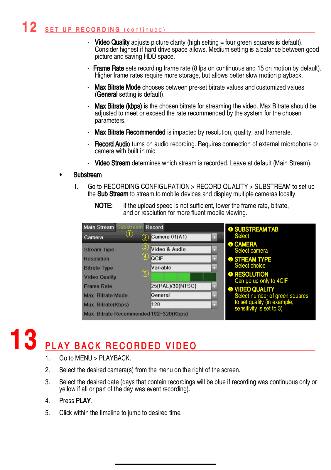
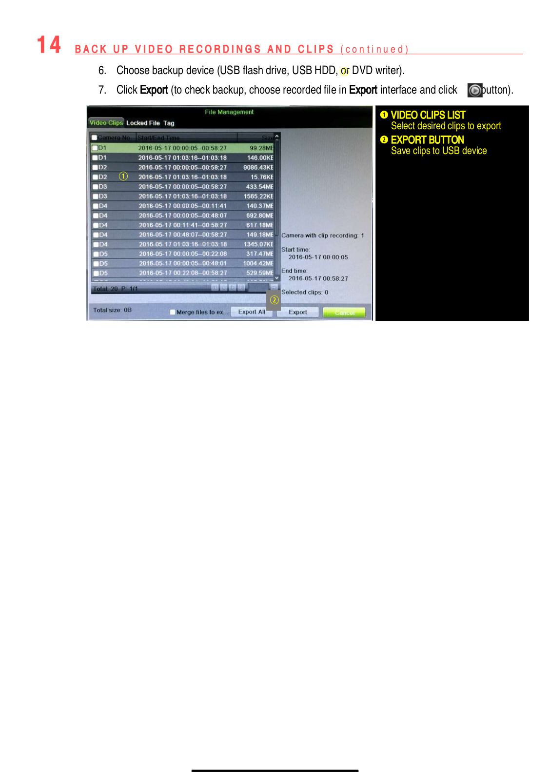
Hikvision DS-7616NXI-4S, DS-7616NXI-12, DS-7608NXI-8P, DS-7608NXI-12, DS-7616NXI-16P User Manual
...
Hikvision DS-7616NXI-4S, DS-7616NXI-12, DS-7608NXI-8P, DS-7608NXI-12, DS-7616NXI-16P, DS-7608NXI-4S User Manual
Download
Specifications and Main Features
Frequently Asked Questions
User Manual
Download
Loading...
+
hidden pages
Unhide
You need points to download manuals.
1 point = 1 manual.
You can buy points or you can get point for every manual you upload.
Buy points
Upload your manuals


 Loading... Loading...