


Hikvision DS-K1T500S User Manual
Video Access Control Terminal
User Manual
UD04154B

Video Access Control Terminal User Manual
User Manual
© 2017 Hangzhou Hikvision Digital Technology Co., Ltd.
It includes instructions on how to use the Product. The software embodied in the Product is governed by the user license agreement covering that Product.
About this Manual
This Manual is subject to domestic and international copyright protection. Hangzhou Hikvision Digital Technology Co.,
Ltd. (“Hikvision”) reserves all rights to this manual. This manual cannot be reproduced, changed, translated, or distributed, partially or wholly, by any means, without the prior written permission of Hikvision.
Trademarks
 and other Hikvision marks are the property of Hikvision and are registered trademarks or the subject of applications for the same by Hikvision and/or its affiliates. Other trademarks mentioned in this manual are the properties of their respective owners. No right of license is given to use such trademarks without express permission.
Disclaimer
TO THE MAXIMUM EXTENT PERMITTED BY APPLICABLE LAW, HIKVISION MAKES NO WARRANTIES, EXPRESS OR IMPLIED, INCLUDING WITHOUT LIMITATION THE IMPLIED WARRANTIES OF MERCHANTABILITY AND FITNESS FOR A PARTICULAR PURPOSE, REGARDING THIS MANUAL. HIKVISION DOES NOT WARRANT, GUARANTEE, OR MAKE ANY REPRESENTATIONS REGARDING THE USE OF THE MANUAL, OR THE CORRECTNESS, ACCURACY, OR RELIABILITY OF INFORMATION CONTAINED HEREIN. YOUR USE OF THIS MANUAL AND ANY RELIANCE ON THIS MANUAL SHALL BE WHOLLY AT YOUR OWN RISK AND RESPONSIBILITY.
REGARDING TO THE PRODUCT WITH INTERNET ACCESS, THE USE OF PRODUCT SHALL BE WHOLLY AT YOUR OWN RISKS. OUR COMPANY SHALL NOT TAKE ANY RESPONSIBILITIES FOR ABNORMAL OPERATION, PRIVACY LEAKAGE OR OTHER DAMAGES RESULTING FROM CYBER ATTACK, HACKER ATTACK, VIRUS INSPECTION, OR OTHER INTERNET SECURITY RISKS; HOWEVER, OUR COMPANY WILL PROVIDE TIMELY TECHNICAL SUPPORT IF REQUIRED.
SURVEILLANCE LAWS VARY BY JURISDICTION. PLEASE CHECK ALL RELEVANT LAWS IN YOUR JURISDICTION BEFORE USING THIS PRODUCT IN ORDER TO ENSURE THAT YOUR USE CONFORMS THE APPLICABLE LAW. OUR COMPANY SHALL NOT BE LIABLE IN THE EVENT THAT THIS PRODUCT IS USED WITH ILLEGITIMATE PURPOSES.
IN THE EVENT OF ANY CONFLICTS BETWEEN THIS MANUAL AND THE APPLICABLE LAW, THE LATER PREVAILS.
Support
Should you have any questions, please do not hesitate to contact your local dealer.
i

Video Access Control Terminal User Manual
Regulatory Information
FCC Information
Please take attention that changes or modification not expressly approved by the party responsible for compliance could void the user’s authority to operate the equipment.
FCC compliance: This equipment has been tested and found to comply with the limits for a Class B digital device, pursuant to part 15 of the FCC Rules. These limits are designed to provide reasonable protection against harmful interference in a residential installation. This equipment generates, uses and can radiate radio frequency energy and, if not installed and used in accordance with the instructions, may cause harmful interference to radio communications. However, there is no guarantee that interference will not occur in a particular installation. If this equipment does cause harmful interference to radio or television reception, which can be determined by turning the equipment off and on, the user is encouraged to try to correct the interference by one or more of the following measures:
—Reorient or relocate the receiving antenna.
—Increase the separation between the equipment and receiver.
—Connect the equipment into an outlet on a circuit different from that to which the receiver is connected.
—Consult the dealer or an experienced radio/TV technician for help.
This equipment should be installed and operated with a minimum distance 20cm between the radiator and your body.
FCC Conditions
This device complies with part 15 of the FCC Rules. Operation is subject to the following two conditions:
1.This device may not cause harmful interference.
2.This device must accept any interference received, including interference that may cause undesired operation.
EU Conformity Statement
This product and - if applicable - the supplied accessories too are marked with "CE" and comply therefore with the applicable harmonized European standards listed under the RE Directive 2014/53/EU, the EMC Directive 2014/30/EU, the RoHS Directive 2011/65/EU.
2012/19/EU (WEEE directive): Products marked with this symbol cannot be disposed of as unsorted municipal waste in the European Union. For proper recycling, return this product to your local supplier upon the purchase of equivalent new equipment, or dispose of it at designated collection points. For more information see: www.recyclethis.info
2006/66/EC (battery directive): This product contains a battery that cannot be disposed of as unsorted municipal waste in the European Union. See the product documentation for specific battery information. The battery is marked with this symbol, which may include lettering to indicate cadmium (Cd), lead (Pb), or mercury (Hg). For proper recycling, return the battery to your supplier or to a designated collection point.
For more information see: www.recyclethis.info
ii
Video Access Control Terminal User Manual
Symbol Conventions
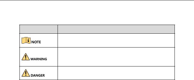
The symbols that may be found in this document are defined as follows.
Symbol Description
Provides additional information to emphasize or supplement important points of the main text.
Indicates a potentially hazardous situation, which if not avoided, could result in equipment damage, data loss, performance degradation, or unexpected results.
Indicates a hazard with a high level of risk, which if not avoided, will result in death or serious injury.
Safety Instructions
Proper configuration of all passwords and other security settings is the responsibility of the installer and/or end-user.
In the use of the product, you must be in strict compliance with the electrical safety regulations of the nation and region. Please refer to technical specifications for detailed information.
Input voltage should meet both the SELV (Safety Extra Low Voltage) and the Limited Power Source with 100~240 VAC or 12 VDC according to the IEC60950-1 standard. Please refer to technical specifications for detailed information.
Do not connect several devices to one power adapter as adapter overload may cause over-heating or a fire hazard.
Please make sure that the plug is firmly connected to the power socket.
If smoke, odor or noise rise from the device, turn off the power at once and unplug the power cable, and then please contact the service center.
Preventive and Cautionary Tips
Before connecting and operating your device, please be advised of the following tips:
Ensure unit is installed in a well-ventilated, dust-free environment.
Unit is designed for indoor use only.
Keep all liquids away from the device.
Ensure environmental conditions meet factory specifications.
Ensure unit is properly secured to a rack or shelf. Major shocks or jolts to the unit as a result of dropping it may cause damage to the sensitive electronics within the unit.
Use the device in conjunction with an UPS if possible.
Power down the unit before connecting and disconnecting accessories and peripherals.
A factory recommended HDD should be used for this device.
Improper use or replacement of the battery may result in hazard of explosion. Replace with the same or equivalent type only. Dispose of used batteries according to the instructions provided by the battery manufacturer.
iii

Video Access Control Terminal User Manual
Table of Contents |
|
1 Overview ................................................................................................................................................................. |
3 |
1.1 Introduction .............................................................................................................................................................. |
3 |
1.2 Main Features ........................................................................................................................................................... |
3 |
2 Appearance ............................................................................................................................................................. |
4 |
2.1 Appearanceof DS-K1T500SF Model........................................................................................................................... |
4 |
2.2 Appearanceof DS-K1T500S Model ............................................................................................................................ |
4 |
2.3 Video Access Control Terminal Connector ................................................................................................................ |
5 |
3 Installation............................................................................................................................................................... |
6 |
4 Terminal Connection................................................................................................................................................ |
7 |
5 Wiring Description ................................................................................................................................................... |
9 |
5.1 External Device Wiring Overview.............................................................................................................................. |
9 |
5.2 The Wiring of External Card Reader ........................................................................................................................ |
10 |
5.2.1 The Wiring of External RS-485 Card Reader ..................................................................................................... |
10 |
5.3 Card Reader Connection ......................................................................................................................................... |
10 |
5.3.1 The Wiring of Wiegand ..................................................................................................................................... |
11 |
5.3.2 The Wiring of RS-485 Output............................................................................................................................ |
11 |
6 Activating the Access Control Terminal ................................................................................................................... |
13 |
6.1 Activating via SADP Software .................................................................................................................................. |
13 |
6.2 Activating via Client Software.................................................................................................................................. |
14 |
7 iVMS-4200 Access Control Client Operation............................................................................................................ |
17 |
7.1 Overview of iVMS-4200 Client Software ................................................................................................................. |
17 |
7.1.1 Description........................................................................................................................................................ |
17 |
7.1.2 Running Environment ....................................................................................................................................... |
17 |
7.1.3 Client Performance ........................................................................................................................................... |
17 |
7.2 User Registration and Login .................................................................................................................................... |
17 |
7.2.1 User Registration .............................................................................................................................................. |
17 |
7.2.2 Login ................................................................................................................................................................. |
18 |
7.2.3 Function Modules ............................................................................................................................................. |
18 |
7.3 Resource Management ........................................................................................................................................... |
22 |
7.3.1 Access Control Device Management ................................................................................................................ |
22 |
7.3.2 Network Settings .............................................................................................................................................. |
43 |
7.3.3 Capture Settings................................................................................................................................................ |
45 |
7.3.4 RS-485 Settings ................................................................................................................................................. |
46 |
7.3.5 Door Group Management................................................................................................................................. |
47 |
7.4 Permission Configuration ........................................................................................................................................ |
50 |
7.4.1 Person Management......................................................................................................................................... |
50 |
7.4.2 Card Management ............................................................................................................................................ |
56 |
7.4.3 Schedule Template............................................................................................................................................ |
62 |
7.4.4 Door Status Management................................................................................................................................. |
67 |
7.4.5 Linkage Configuration ....................................................................................................................................... |
71 |
7.4.6 Permission Configuration.................................................................................................................................. |
75 |
7.4.7 Advanced Functions.......................................................................................................................................... |
79 |
7.5 Event and Alarm Management................................................................................................................................ |
92 |
7.5.1 Real-Time Access Control Event and Alarm ...................................................................................................... |
92 |
7.5.2 Event Management........................................................................................................................................... |
93 |
7.6 System Maintenance ............................................................................................................................................... |
95 |
7.6.1 Log Management.............................................................................................................................................. |
95 |
7.6.2 Account Management ...................................................................................................................................... |
96 |
7.6.3 Auto Backup Settings ........................................................................................................................................ |
97 |
7.6.4 System Configuration........................................................................................................................................ |
97 |
8 iVMS-4200 Control Client Operation ..................................................................................................................... |
102 |
8.1 Importing Access Control Device........................................................................................................................... |
102 |
8.2 Live View and Playcak Settings .............................................................................................................................. |
102 |
1

Video Access Control Terminal User Manual
8.3 Group Management .............................................................................................................................................. |
104 |
|
8.3.1 Adding the Group ........................................................................................................................................... |
104 |
|
8.3.2 Importing Encoding Device to Group.............................................................................................................. |
105 |
|
8.3.3 Editing the Group/Camera.............................................................................................................................. |
106 |
|
8.3.4 Removing Cameras from the Group ............................................................................................................... |
106 |
|
8.3.5 Deleting the Group ......................................................................................................................................... |
107 |
|
8.4 Live View ............................................................................................................................................................... |
107 |
|
8.4.1 Starting and Stopping the Live View ............................................................................................................... |
110 |
|
8.4.2 Manual Recording and Capture ...................................................................................................................... |
112 |
|
8.4.3 Instant Playback .............................................................................................................................................. |
114 |
|
8.4.4 Custom Window Division................................................................................................................................ |
116 |
|
8.4.5 Other Functions in Live View .......................................................................................................................... |
117 |
|
8.5 |
Playback................................................................................................................................................................. |
118 |
8.5.1 Storing on Storage Device............................................................................................................................... |
118 |
|
8.5.2 Normal Playback ............................................................................................................................................. |
120 |
|
8.5.3 Event Playback ................................................................................................................................................ |
127 |
|
9 Appendix .............................................................................................................................................................. |
130 |
|
9.1 |
Tips for Scanning Fingerprint................................................................................................................................. |
130 |
9.2 |
DIP Switch Introduction......................................................................................................................................... |
131 |
9.3 |
Indicator and Buzzer Description .......................................................................................................................... |
132 |
9.4 |
Access Controller Model List ................................................................................................................................. |
133 |
2
Video Access Control Terminal User Manual
1 Overview
1.1 Introduction
DS-K1T500S/SF is a series video access control terminal with multiple advanced technologies including fingerprint recognition, face detection, Wi-Fi, smart card recognition, and HD camera (2 MP optional). It is equipped with fingerprint recognition module (supporting 1:1 mode and 1:N mode), and supports offline operation.
1.2 Main Features
Doorbell ringtone settings function
Stand-alone settings for the terminal
Transmission modes of wired network (TCP/TP), Wi-Fi, RS-485, and Wiegand
Face detection and picture capturing function implemented by built-in camera (2 MP optional)
Supports RS-485 communication for connecting external card reader
Supports working as a card reader, and supports Wiegand interface and RS-485 interface for accessing the controller
Supports EHome
Max. 50,000 cards Max. 200,000 access control events records, and Max.3000 fingerprints storage(Only supported by DS-K1T500SF )
Adopts fingerprint module, supporting 1:N mode (fingerprint, card + fingerprint) and 1:1 mode (card + fingerprint)
Supports multiple authentication modes including card, fingerprint, card + fingerprint, card + password, fingerprint + password, card + fingerprint + password, and so on.(The fingerprint authentication mode is only supported by DS-K1T500SF)
Supports Mifare card/ QR Code reading
Tampering detection, unlocking overtime alarm, invalid card swiping over times alarm, duress card alarm, and so on
Supports security door control unit connection
Protection level: IP65
Data can be permanently saved after power-off
3
Video Access Control Terminal User Manual
2 Appearance
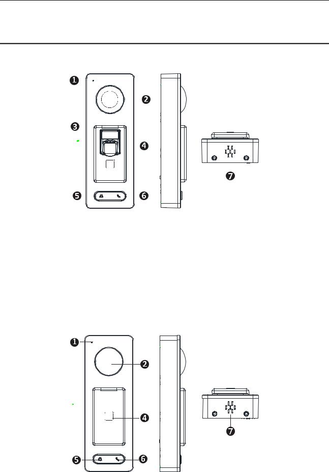
2.1 Appearanceof DS-K1T500SF Model
Please refer to the following content for detailed information of the 2.1 DS-K1T500SF model.
Table 2-1 Description of DS-K1T500SF Series Model
No. |
Description |
1 |
Mic |
|
|
2 |
Camera |
|
|
3 |
LED Indicator |
|
|
4 |
Fingerprint Scanner and Card Swiping Area |
|
|
5 |
Doorbell Button |
|
|
6 |
Voice Talk Button |
|
|
7 |
Loud Speaker |
|
|
2.2 Appearanceof DS-K1T500S Model
Please refer to the following content for detailed information of DS-K1T500S series model
4

Video Access Control Terminal User Manual
Table 2-2 Description of DS-K1T500S Series Model
No. |
Description |
1 |
Mic |
|
|
2 |
Camera |
|
|
3 |
LED Indicator |
|
|
4 |
Card Swiping Area |
|
|
5 |
Doorbell Button |
|
|
6 |
Voice Talk Button |
|
|
7 |
Loud Speaker |
|
|
In the Event Card Interact interface in the iVMS-4200 Client Software, choose the alarm output of Event Bell. You can connect a bell at the alarm output terminal. For details about configuring the Event Bell alarm output, see the User Manual of iVMS4200 Client Software.
2.3 Video Access Control Terminal Connector
5

Video Access Control Terminal User Manual
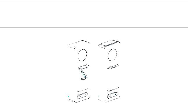
3 Installation
Before You Start:
Make sure that the device in the package is in good condition and all the assembly parts are included.
Make sure that the wall is strong enough to withstand three times the weight of the terminal.
Set the DIP address before installation.
Steps:
1.Connect the cables with the connecter on the
rear panel of the device. Route the cables through the cable hole of the mounting plate. The cable holes are on the right side, left side and lower side of the rear cover. If the right/left side cable hole is selected, remove the plastic sheet of the cable hole.
2. Secure the mounting plate on the wall with 4 supplied screws.
3. Connect the corresponding cables.
4. Push the terminal in the mounting plate from bottom up.
5.Tighten the screws on the bottom of the
terminal to fix the terminal on the mounting plate and complete the installation.
6

Video Access Control Terminal User Manual
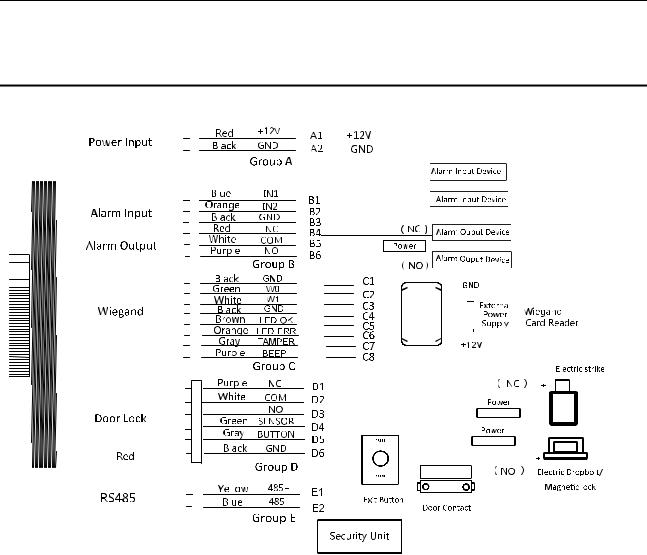
4 Terminal Connection
7

Video Access Control Terminal User Manual
Table 4-1 Terminal Description
|
Group |
|
|
No. |
|
|
Function |
|
|
Color |
|
|
Terminal |
|
|
Description |
|
|
|
|
|
|
|
|
|
|
Name |
|
|
|
|||||
|
|
|
|
|
|
|
|
|
|
|
|
|
|
|
|
|
|
|
|
|
|
A1 |
|
|
|
|
Red |
|
+12V |
|
12V DC Power Supply |
||||
|
Group A |
|
|
Power Input |
|
|
|
|
|
||||||||
|
|
|
|
|
|
|
|
|
|
|
|
|
|
||||
|
|
A2 |
|
|
Black |
|
GND |
|
GND |
||||||||
|
|
|
|
|
|
|
|
|
|
||||||||
|
|
|
|
|
|
|
|
|
|
|
|
||||||
|
|
|
|
|
|
|
|
|
|
|
|
|
|
||||
|
|
|
|
B1 |
|
|
|
|
Yellow |
|
IN1 |
|
Alarm Input 1 |
||||
|
|
|
|
B2 |
|
Alarm Input |
|
Orange |
|
IN2 |
|
Alarm Input 2 |
|||||
|
Group B |
|
B3 |
|
|
|
|
Black |
|
GND |
|
GND |
|||||
|
|
B4 |
|
|
|
|
Red |
|
NC |
|
|
|
|||||
|
|
|
|
|
|
|
|
|
|
|
|
||||||
|
|
|
|
B5 |
|
Alarm Output |
|
White |
|
COM |
|
Alarm Output Wiring |
|||||
|
|
|
|
B6 |
|
|
|
|
Purple |
|
NO |
|
|
|
|||
|
|
|
|
C1 |
|
|
|
|
Black |
|
GND |
|
GND |
||||
|
|
|
|
|
|
|
|
|
|
|
|
|
|
|
|
|
|
|
|
|
|
C2 |
|
|
|
|
Green |
|
W0 |
|
Wiegand Wiring 0 |
||||
|
|
|
|
|
|
|
|
|
|
|
|
||||||
|
|
|
|
|
|
|
|
|
|
|
|
|
|
|
|
|
|
|
|
|
|
C3 |
|
|
|
|
White |
|
W1 |
|
Wiegand Wiring 1 |
||||
|
|
|
|
|
|
|
|
|
|
|
|
||||||
|
|
|
|
|
|
|
|
|
|
|
|
|
|
||||
|
Group C |
|
C4 |
|
Wiegand |
|
Black |
|
GND |
|
GND |
||||||
|
|
C5 |
|
|
Brown |
|
LED-OK |
|
Wiegand |
||||||||
|
|
|
|
|
|
|
|
|
|
||||||||
|
|
|
|
|
|
|
|
|
|
Authenticated |
|||||||
|
|
|
|
|
|
|
|
|
|
|
|
|
|
|
|
||
|
|
|
|
C6 |
|
|
|
|
Orange |
|
LED-ERR |
|
Wiegand |
||||
|
|
|
|
|
|
|
|
|
|
Authentication Failed |
|||||||
|
|
|
|
|
|
|
|
|
|
|
|
|
|
|
|
||
|
|
|
|
C7 |
|
|
|
|
Gray |
|
TAMPER |
|
Tampering Alarm |
||||
|
|
|
|
|
|
|
|
|
|
Wiring |
|||||||
|
|
|
|
|
|
|
|
|
|
|
|
|
|
|
|
||
|
|
|
|
C7 |
|
|
|
|
Purple |
|
BEEP |
|
Buzzer Wiring |
||||
|
|
|
|
D1 |
|
|
|
|
Purple |
|
NC |
|
Lock Wiring |
||||
|
|
|
|
D2 |
|
|
|
|
White |
|
COM |
|
|||||
|
|
|
|
|
|
|
|
|
|
|
|
||||||
|
|
|
|
D3 |
|
|
|
|
Red |
|
NO |
|
|
|
|||
|
Group D |
|
D4 |
|
Lock |
|
Green |
|
SENSOR |
|
Door Magnetic Signal |
||||||
|
|
|
|
|
|
Input |
|||||||||||
|
|
|
|
|
|
|
|
|
|
||||||||
|
|
|
|
|
|
|
|
|
|
|
|
|
|
|
|
||
|
|
|
|
|
|
|
|
|
|
|
|
|
|
|
|
|
|
|
|
|
|
D5 |
|
|
|
|
Gray |
|
BUTTON |
|
Exit Door Wiring |
||||
|
|
|
|
|
|
|
|
|
|
|
|
||||||
|
|
|
|
|
|
|
|
|
|
|
|
|
|
||||
|
|
|
|
D6 |
|
|
|
|
Black |
|
GND |
|
GND |
||||
|
Group E |
|
E1 |
|
RS-485 |
|
Yellow |
485 + |
|
|
RS-485 Wiring |
||||||
|
|
E2 |
|
|
Blue |
485 - |
|
|
|||||||||
|
|
|
|
|
|
|
|
|
|
|
|
||||||
8
Video Access Control Terminal User Manual
5 Wiring Description
5.1 External Device Wiring Overview
9
Video Access Control Terminal User Manual
5.2 The Wiring of External Card Reader
5.2.1 The Wiring of External RS-485 Card Reader
If set the working mode as the controller mode, the DIP switch No.6 should be set as OFF.
If set the working mode as card reader mode, the DIP switch No. from 1 to 4 should be set as OFF. The terminal can connect to the RS-485 card reader.
5.3 Card Reader Connection
The access control terminal can be switched into the card reader mode. It can access to the access control as a card reader, and supports Wiegand communication port and RS-485 communication port.
When the access control terminal works as a card reader, it only supports being connected to the controller, but does not support alarm input or output, or the connection of external devices.
10
Video Access Control Terminal User Manual
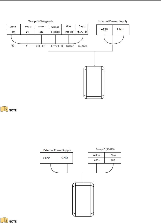
5.3.1 The Wiring of Wiegand
When the access control terminal works as a card reader, you must the WG_ERR, BUZZER and WG_OK interfaces if you want to control the LED and buzzer of the Wiegand card reader.
Set the working mode of the terminal as card reader, if the terminal is required to work as a card reader. The card reader mode support to communicate by Wiegand or RS-485.
The distance of Wiegand communication should be no longer than 80 m.
The external power supply and the access control terminal should use the same GND cable.
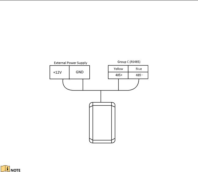
5.3.2 The Wiring of RS-485 Output
Set the working mode of the terminal as card reader, if the terminal requires working as a card reader.
When the access control terminal works as a RS-485 card reader, the default RS-485 address is 1.
11

Video Access Control Terminal User Manual
The external power supply and the access control terminal should use the same GND cable.
12
Video Access Control Terminal User Manual
6 Activating the Access Control Terminal
Purpose:
You are required to activate the terminal first before using it.
Activation via SADP, and Activation via client software are supported.
The default values of the control terminal are as follows.
The default IP address: 192.0.0.64.
The default port No.: 8000.
The default user name: admin.
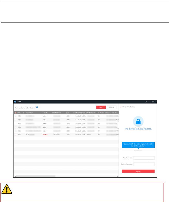
6.1 Activating via SADP Software
SADP software is used for detecting the online device, activating the device, and resetting the password.
Get the SADP software from the supplied disk or the official website, and install the SADP according to the prompts. Follow the steps to activate the control panel.
Steps:
1.Run the SADP software to search the online devices.
2.Check the device status from the device list, and select an inactive device.
3.Create a password in the password field, and confirm the password.
STRONG PASSWORD RECOMMENDED– We highly recommend you create a strong password of your own choosing (using a minimum of 8 characters, including upper case letters, lower case letters, numbers, and special characters) in order to increase the security of your product. And we recommend you reset your password regularly, especially in the high security system, resetting the password monthly or weekly can better protect your product.
4.Click Activate to activate the device.
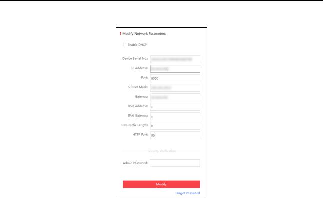
5.Check the activated device, you can change the device IP address to the same network segment with your computer by either modifying the IP address manually or checking the checkbox of Enable DHCP.
13
Video Access Control Terminal User Manual
6.Input the password and click the Modify button to activate your IP address modification.
6.2 Activating via Client Software
The client software is versatile video management software for multiple kinds of devices.
Get the client software from the supplied disk or the official website, and install the software according to the prompts. Follow the steps to activate the control panel.
Steps:
1.Run the client software and the control panel of the software pops up, as shown in the figure below.
14
Video Access Control Terminal User Manual
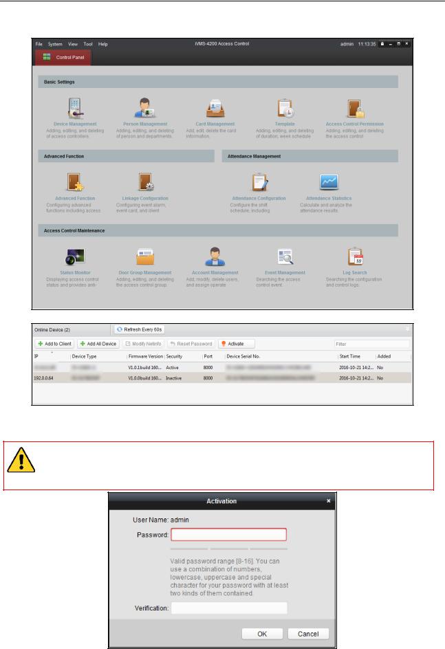
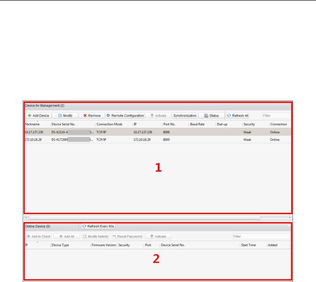
2.Click the Device Management to enter the Device Management interface.
3.Check the device status from the online device list, and select an inactive device.
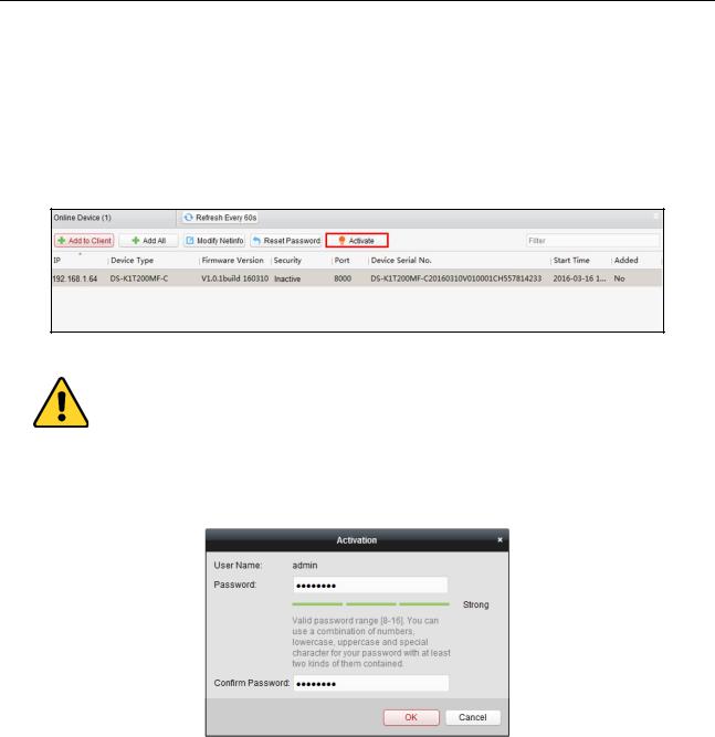
4.Click the Activate button to pop up the Activation interface.
5.In the pop-up window, create a password in the password field, and confirm the password.
STRONG PASSWORD RECOMMENDED– We highly recommend you create a strong password of your own choosing (using a minimum of 8 characters, including upper case letters, lower case letters, numbers, and special characters) in order to increase the security of your product. And we recommend you reset your password regularly, especially in the high security system, resetting the password monthly or weekly can better protect your product.
15
Video Access Control Terminal User Manual
6.Click OK button to activate.
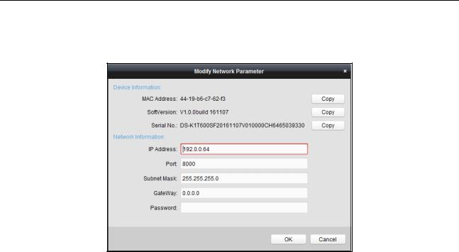
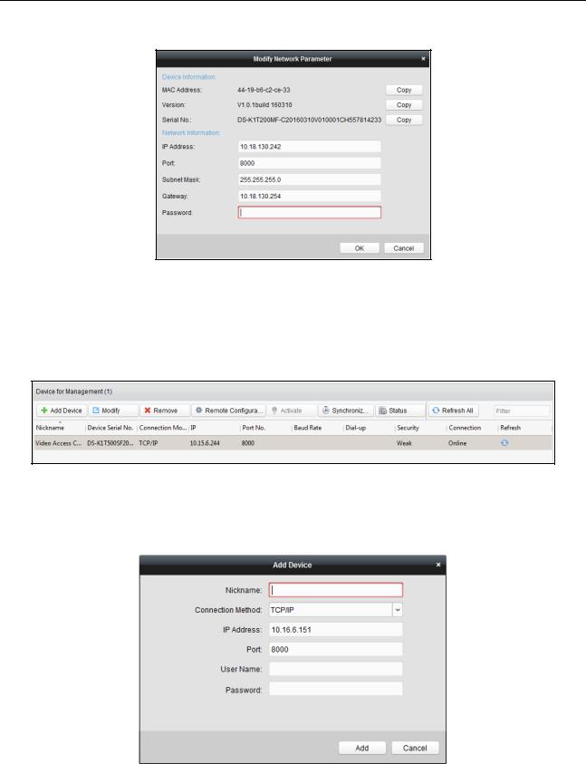
7.Click the Modify Netinfor button to pop up the Network Parameter Modification interface.
8.Change the device IP address to the same network segment with your computer by either modifying the IP address manually.
9.Input the password and click the OK button to save the settings.
16
Video Access Control Terminal User Manual
7 iVMS-4200 Access Control Client Operation
7.1 Overview of iVMS-4200 Client Software
7.1.1 Description
The iVMS-4200 Access Control Client is a client-based access control system for management of access control devices. With intuitive and easy-to-use operations, it provides multiple functionalities, including access control device management, person/card management, permission configuration, door status management, attendance management, event search, etc.
This user manual describes the function, configuration and operation steps of iVMS-4200 Access Control Client. To ensure the properness of usage and stability of the client, please refer to the contents below and read the manual carefully before installation and operation.
7.1.2 Running Environment
Operating System: Microsoft Windows 7/Windows 2008 R2/Windows 8.1/Windows 10 (32-bit or 64-bit), Windows XP SP3 (32-bit)
CPU: Intel Pentium IV 3.0 GHz or above Memory: 2G or above
Video Card: RADEON X700 Series or above GPU: 256 MB or above
For high stability and good performance, these above system requirements must be met.
The software does not support 64-bit operating system; the above mentioned 64-bit operating system refers to the system which supports 32-bit applications as well.
7.1.3 Client Performance
The client performance is shown as follows:
Client Performance |
Quantity |
User Account |
Up to 16 user accounts (including super user) supported |
|
|
Access Control Device |
Up to 16 access control devices supported |
|
|
Access Control Point |
Up to 64 access control points (doors) supported |
|
|
Person |
Up to 2,000 persons supported |
|
|
Card |
Up to 2,000 cards supported |
Department |
Up to 10 levels of departments supported |
|
|
7.2 User Registration and Login
For the first time using the client software, you need to register a super user to login.
7.2.1 User Registration
Steps:
1. Double-click  on the desktop to run the client.
17
Video Access Control Terminal User Manual
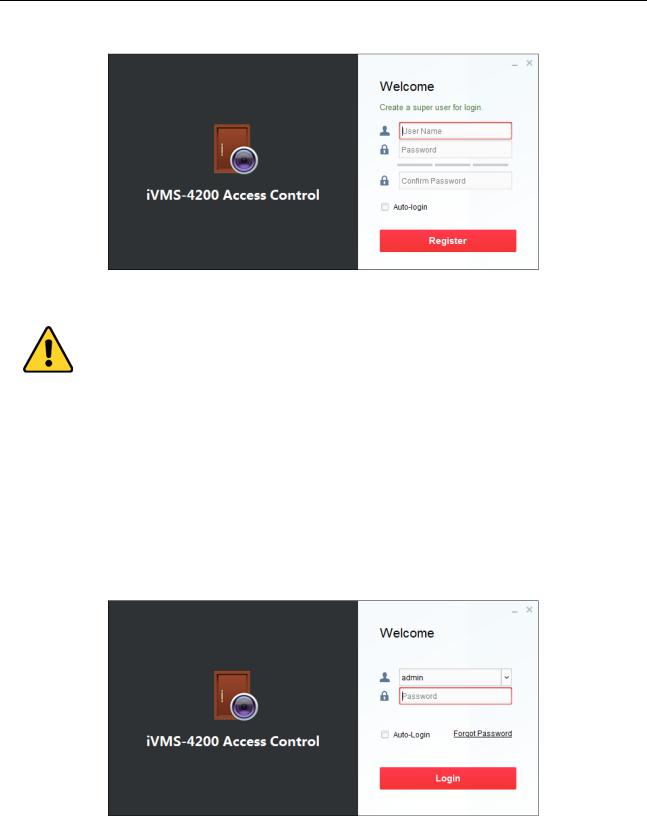
2.Input the super user name, password and confirm password in the pop-up window.
3.Optionally, check the checkbox Auto-login to log in to the software automatically.
4.Click Register. Then, you can log in to the software as the super user.
A user name cannot contain any of the following characters: / \ : * ? “ < > |. And the length of the password cannot be less than 8 characters.
For your privacy, we strongly recommend changing the password to something of your own choosing (using a minimum of 8 characters, including upper case letters, lower case letters, numbers, and special characters) in order to increase the security of your product.
Proper configuration of all passwords and other security settings is the responsibility of the installer and/or end-user.
When opening iVMS-4200 Access Control Client after registration, you can log in to the client software with the registered user name and password.
7.2.2 Login
Steps:
1. Input the user name and password you registered.
2.Optionally, check the checkbox Auto-login to log in to the software automatically.
3.Optionally, if you forget your password, please click Forgot Password and remember the encrypted string in the pop-up window. Contact your dealer and send the encrypted string to him to reset your password.
4.Click Login.
7.2.3 Function Modules
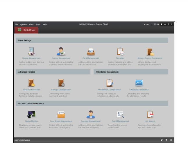
After login, the control panel of the Access Control Client is shown as follows:
18
Video Access Control Terminal User Manual
Control Panel of iVMS-4200 Access Control Client:
Menu Bar:
File |
|
Exit |
|
Exit the iVMS-4200 Access Control Client. |
|
|
Lock |
|
Lock screen operations. Log in the client again to |
|
|
|
||
|
|
|
unlock. |
|
|
|
|
|
|
|
|
Switch User |
|
Switch the login user. |
System |
|
Import Parameters |
|
Import client configuration file from your computer. |
|
|
Export Parameters |
|
Export client configuration file to your computer. |
|
|
Auto Backup |
|
Back up the database including person, attendance |
|
|
|
||
|
|
|
data, and permission data automatically. |
|
|
|
|
|
|
|
|
Device Management |
|
Open the Device Management page. |
|
|
Attendance Configuration |
|
Open the Attendance Configuration page. |
|
|
Attendance Statistics |
|
Open the Attendance Statistics page. |
|
|
Person Management |
|
Open the Person Management page. |
|
|
Card Management |
|
Open the Card Management page. |
View |
|
Template |
|
Open the Template page. |
|
|
Access Control Permission |
|
Open the Access Control Permission page. |
|
|
Advanced Function |
|
Open the Advanced Function page. |
|
|
Status Monitor |
|
Open the Status Monitor page. |
|
|
Linkage Configuration |
|
Open the Linkage Configuration page. |
|
|
Door Group Management |
|
Open the Door Group Management page. |
|
|
|
|
|
19

Video Access Control Terminal User Manual
|
|
|
|
Account Management |
|
Open the Account Management page. |
|
|
|
|
Event Management |
|
Open the Event Management page. |
|
|
|
|
Log Search |
|
Open the Log Search page. |
|
|
|
|
Control Panel |
|
Enter Control Panel interface. |
|
|
|
|
Search Access Control |
|
Search the added access control permission. |
|
|
|
|
Permission |
|
|
|
|
|
|
|
|
|
|
|
|
|
Card Reader |
|
Configure the card reader parameters. |
|
|
|
|
Fingerprint Machine |
|
Configure the fingerprint machine parameters. |
|
Tools |
|
|
Storage Server |
|
Configure the storage server parameters. |
|
|
|
System Configuration |
|
Enter the System Configuration page. |
|
|
|
|
|
|
||
|
|
|
|
People Counting |
|
Enter the People Counting page. |
|
|
|
|
Apply Parameters |
|
Apply the settings on the client to the corresponding |
|
|
|
|
|
||
|
|
|
|
|
access control device. |
|
|
|
|
|
|
|
|
|
|
|
|
Arming Settings |
|
Set the arming status of access control devices. |
|
|
|
|
User Manual (F1) |
|
Click to open the User Manual; you can also open the |
|
|
|
|
|
||
|
|
|
|
|
User Manual by pressing F1 on your keyboard. |
|
|
|
|
|
|
|
|
|
Help |
|
|
Language |
|
Select the language for the client software and reboot |
|
|
|
|
|||
|
|
|
|
|
the software to activate the settings. |
|
|
|
|
|
|
|
|
|
|
|
|
About |
|
View the basic information of the client software. |
|
|
|
|
|
|
|
The iVMS-4200 Access Control Client is composed of the following function modules:
Device Management
Person Management
Card Management
Template
Access Control
Permission
Advanced Function
The Device Management module provides adding, editing, and deleting of access controllers.
The Person Management module provides adding, editing, and deleting of person and departments.
The Card Management module provides adding, editing, and deleting the card information.
The Template module provides adding, deleting, and editing of duration, week plan, and holiday.
The Access Control Permission module provides adding, deleting, and applying the access control permissions.
The Advanced Function module provides configuration of advanced functions including access control type, anti-passing back, multiple interlocking, etc..
Linkage Configuration
Attendance
Configuration
Attendance Statistics
The Linkage Configuration module provides event alarm, event card, and client linkage configuration.
The Attendance Configuration module provides shift schedule settings including attendance rule, attendance check point, holiday schedule, etc.
The Attendance Statistics module provides calculating and analyzing the attendance results.
20

Video Access Control Terminal User Manual
Status Monitor
Door Group
Management
Account Management
Event Management
Log Search
The Status Monitor module displays access control status and provides anti-control function.
The Door Group Management module provides adding, editing, and deleting the access control group.
The Account Management module provides adding, editing, and deleting the user and assigning permission.
The Event Management module provides setting the search condition to search the access control event.
The Log Search module provides searching the configuration logs and control logs.
The function modules are easily accessed by clicking the navigation buttons on the control panel or by selecting the function module from the View menu.
You can check the information, including current user and time, in the upper-right corner of the main page.
21
Video Access Control Terminal User Manual
7.3 Resource Management
After running the iVMS-4200 Access Control Client, the access control device should be added to the client for the remote configuration and management.
7.3.1 Access Control Device Management
Click  icon on the control panel to enter the access control device management interface.
The interface is divided into two parts: Device Management area and Online Device Detection area.
Device Management
Manage the access control devices, including adding, editing, deleting, and batch time synchronizing functions.
Online Device Detection
Automatically detect online devices in the same subnet with the client, and the detected devices can be added to the client in an easy way.
Note: The client can manage up to 16 access control devices and 64 access control points.
22
Video Access Control Terminal User Manual
Activating Device and Creating Password
Purpose:
If the access control device is not activated, you are required to create the password to activate them before they can be added to the software and work properly.
Steps:
1.On the Device for Management or Online Device area, check the device status (shown on Security column) and select an inactive device.
2.Click the Activate button to pop up the Activation interface.
3.Create a password in the password field, and confirm the password.
STRONG PASSWORD RECOMMENDED– We highly recommend you create a strong password of your own choosing (using a minimum of 8 characters, including upper case letters, lower case letters, numbers, and special characters) in order to increase the security of your product. And we recommend you reset your password regularly, especially in the high security system, resetting the password monthly or weekly can better protect your product.
4.Click OK to create the password for the device. A “The device is activated.” window pops up when the password is set successfully.
5.Perform the following steps to edit the device’s network parameters.
1)Click Modify Netinfo to pop up the Modify Network Parameter interface.
Note: This function is only available on the Online Device area. You can change the device IP address to the same subnet with your computer if you need to add the device to the software.
2)Input the password set in step 3 and click OK to complete the network settings.
23
Video Access Control Terminal User Manual
3)Click OK to save the settings.
Adding Online Devices
Purpose:
The active online access control devices in the same local subnet with the client will be displayed on the Online Device area. You can click the Refresh Every 60s button to refresh the information of the online devices.
Note: You can click  to hide the Online Device area.
Steps:
1.Select the devices to be added from the list.
Note: For the inactive device, you need to create the password for it before you can add the device properly. For detailed steps, please refer to 3.1.1 Activating Device and Creating Password.
2.Click Add to Client to open the device adding dialog box.
3.Input the required information.
Nickname: Edit a name for the device as you want. Connection Type: Select TCP/IP as the connection type.
IP Address: Input the device’s IP address. The IP address of the device is obtained automatically in this adding mode.
24
Video Access Control Terminal User Manual
Port: Input the device port No.. The default value is 8000.
User Name: Input the device user name. By default, the user name is admin.
Password: Input the device password.
4.Click Add to add the device to the client.
5.(Optional) If you want to add multiple online devices to the client software, click and hold Ctrl key to select multiple devices, and click Add to Client to open the device adding dialog box. In the pop-up message box, enter the user name and password for the devices to be added.
If you want to add all the online devices to the client software, click Add All and click OK in the pop-up message box. Then enter the user name and password for the devices to be added.
6.You can select the device from the list and click Reset Password to reset the device password.
Perform the following steps to reset the device password.
1)Click Export to save the device file on your PC.
2)Send the file to our technical engineers.
3)Our technical engineer will send you a file or an eight-digit number to you.
If you receive a file from the technical engineer, select Import File from Key Importing Mode drop-down list and click  to import the file.
If you receive an eight-digit number from the technical engineer, select Input Key from Key Importing Mode drop-down list and input the number.
4)Input new password in text fields of Password and Confirm Password.
5)Click OK to reset the password.
The password strength of the device can be checked by the software. For your privacy, we strongly recommend changing the password to something of your own choosing (using a minimum of 8 characters, including upper case letters, lower case letters, numbers, and special characters) in order to increase the security of your product. And we recommend you reset your password regularly, especially in the high security system, resetting the password monthly or weekly can better protect your product.
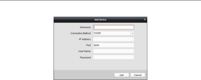
Adding Access Control Device Manually
Steps:
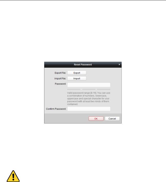
1. Click Add Device on the Device for Management panel to enter the Add Device interface.
25
Video Access Control Terminal User Manual
2.Input the device name.
3.Select the connection type in the dropdown list: TCP/IP, COM port (1 to 5), or EHome protocol. TCP/IP: Connect the device via the network.
COM1 to COM5: Connect the device via the COM port. EHome: Connect the device via EHome Protocol.
Note: For connection type of EHome protocol, please set the network center parameter first. For details, refer to 3.2.2 Network Center Settings.
4.Set the parameters of connecting the device.
If you select the connection type as TCP/IP, you should input the device IP Address, Port No., User Name, and Password.
If you select the connection type as COM port, you should input the Baud Rate and Dial-up value. If you select the connection type as EHome, you should input the Account.
5.Click Add button to finish adding.
Editing Access Control Device
Purpose:
After adding the device, you can configure the added access control device’s parameters, its access control point
(door)’s parameters, and its card readers’ parameters.
Click to select the added access control device from the list, and then click Modify button to enter the Edit Access Controller interface.
Notes:
After editing the device, you can click Apply Parameters to apply the configured parameters to the device to take effect.
You can also click Read Parameters to get the device parameters from the device itself.
Editing Basic Information
You can configure the device basic information including IP address, port No., etc.
Steps:
1.In the device list on the left, select the access control device and you can edit its basic parameters on your demand, which are the same as the ones when adding the device.
26
 Loading...