


Hikvision DS-K1T105E-C, DS-K1T105E User Manual
Access Control Terminal
User Manual
V1.1.0
UD01651B

Access Control Terminal·User Manual
User Manual
© 2016 Hangzhou Hikvision Digital Technology Co., Ltd.
This User Manual is intended for users of the models below:
|
Series |
|
Model |
|
Standalone Access Control |
|
DS-K1T105E/M |
|
|
|
|
|
Terminal |
|
DS-K1T105E/M-C with Camera |
|
|
|
|
|
Optical IP-Based |
|
DS-K1T200EF/MF |
|
Fingerprint |
|
|
|
|
DS-K1T200EF/MF-C with Camera |
|
|
Access Control Terminal |
|
|
|
|
|
|
|
|
|
|
It includes instructions on how to use the Product. The software embodied in the Product is governed by the user license agreement covering that Product.
About this Manual
This Manual is subject to domestic and international copyright protection. Hangzhou Hikvision Digital Technology Co., Ltd.
(“Hikvision”) reserves all rights to this manual. This manual cannot be reproduced, changed, translated, or distributed, partially or wholly, by any means, without the prior written permission of Hikvision.
Trademarks
 and other Hikvision marks are the property of Hikvision and are registered trademarks or the subject of applications for the same by Hikvision and/or its affiliates. Other trademarks mentioned in this manual are the properties of their respective owners. No right of license is given to use such trademarks without express permission.
Legal Disclaimer
TO THE MAXIMUM EXTENT PERMITTED BY APPLICABLE LAW, THE PRODUCT DESCRIBED, WITH ITS HARDWARE, SOFTWARE AND
FIRMWARE, IS PROVIDED “AS IS”, WITH ALL FAULTS AND ERRORS, AND HIKVISION MAKES NO WARRANTIES, EXPRESS OR IMPLIED,
INCLUDING WITHOUT LIMITATION, MERCHANTABILITY, SATISFACTORY QUALITY, FITNESS FOR A PARTICULAR PURPOSE, AND NON-INFRINGEMENT OF THIRD PARTY. IN NO EVENT WILL HIKVISION, ITS DIRECTORS, OFFICERS, EMPLOYEES, OR AGENTS BE LIABLE TO YOU FOR ANY SPECIAL, CONSEQUENTIAL, INCIDENTAL, OR INDIRECT DAMAGES, INCLUDING, AMONG OTHERS, DAMAGES FOR LOSS OF BUSINESS PROFITS, BUSINESS INTERRUPTION, OR LOSS OF DATA OR DOCUMENTATION, IN CONNECTION WITH THE USE OF THIS PRODUCT, EVEN IF HIKVISION HAS BEEN ADVISED OF THE POSSIBILITY OF SUCH DAMAGES.
REGARDING TO THE PRODUCT WITH INTERNET ACCESS, THE USE OF PRODUCT SHALL BE WHOLLY AT YOUR OWN RISKS. HIKVISION SHALL NOT TAKE ANY RESPONSIBILITIES FOR ABNORMAL OPERATION, PRIVACY LEAKAGE OR OTHER DAMAGES RESULTING FROM CYBER ATTACK, HACKER ATTACK, VIRUS INSPECTION, OR OTHER INTERNET SECURITY RISKS; HOWEVER, HIKVISION WILL PROVIDE TIMELY TECHNICAL SUPPORT IF REQUIRED.
SURVEILLANCE LAWS VARY BY JURISDICTION. PLEASE CHECK ALL RELEVANT LAWS IN YOUR JURISDICTION BEFORE USING THIS PRODUCT IN ORDER TO ENSURE THAT YOUR USE CONFORMS THE APPLICABLE LAW. HIKVISION SHALL NOT BE LIABLE IN THE EVENT THAT THIS PRODUCT IS USED WITH ILLEGITIMATE PURPOSES.
IN THE EVENT OF ANY CONFLICTS BETWEEN THIS MANUAL AND THE APPLICABLE LAW, THE LATER PREVAILS.
Support
Should you have any questions, please do not hesitate to contact your local dealer.
i
Access Control Terminal·User Manual
Regulatory Information
FCC Information
FCC compliance: This equipment has been tested and found to comply with the limits for a digital device, pursuant to part 15 of the FCC Rules. These limits are designed to provide reasonable protection against harmful interference when the equipment is operated in a commercial environment. This equipment generates, uses, and can radiate radio frequency energy and, if not installed and used in accordance with the instruction manual, may cause harmful interference to radio communications. Operation of this equipment in a residential area is likely to cause harmful interference in which case the user will be required to correct the interference at his own expense.
FCC Conditions
This device complies with part 15 of the FCC Rules. Operation is subject to the following two conditions:
1.This device may not cause harmful interference.
2.This device must accept any interference received, including interference that may cause undesired operation.
EU Conformity Statement
This product and - if applicable - the supplied accessories too are marked with "CE" and comply therefore with the applicable harmonized European standards listed under the Low Voltage Directive 2006/95/EC, the EMC Directive 2004/108/EC, the RoHS Directive 2011/65/EU.
2012/19/EU (WEEE directive): Products marked with this symbol cannot be disposed of as unsorted municipal waste in the European Union. For proper recycling, return this product to your local supplier upon the purchase of equivalent new equipment, or dispose of it at designated collection points. For more information see: www.recyclethis.info.
2006/66/EC (battery directive): This product contains a battery that cannot be disposed of as unsorted municipal waste in the European Union. See the product documentation for specific battery information. The battery is marked with this symbol, which may include lettering to indicate cadmium (Cd), lead (Pb), or mercury (Hg). For proper recycling, return the battery to your supplier or to a designated collection point. For more information see: www.recyclethis.info.
Industry Canada ICES-003 Compliance
This device meets the CAN ICES-3 (A)/NMB-3(A) standards requirements.
Safety Instruction
These instructions are intended to ensure that user can use the product correctly to avoid danger or property loss. The precaution measure is divided into Warnings and Cautions:
Warnings: Neglecting any of the warnings may cause serious injury or death. Cautions: Neglecting any of the cautions may cause injury or equipment damage.
|
|
Warnings Follow |
Cautions Follow these |
these safeguards to |
precautions to prevent |
prevent serious |
potential injury or |
injury or death. |
material damage. |
|
|
Warnings
All the electronic operation should be strictly compliance with the electrical safety regulations, fire prevention regulations and other related regulations in your local region.
Please use the power adapter, which is provided by normal company. The power consumption cannot be less than the required value.
Do not connect several devices to one power adapter as adapter overload may cause over-heat or fire hazard.
Please make sure that the power has been disconnected before you wire, install or dismantle the device.
When the product is installed on wall or ceiling, the device shall be firmly fixed.
ii

Access Control Terminal·User Manual
If smoke, odors or noise rise from the device, turn off the power at once and unplug the power cable, and then please contact the service center.
If the product does not work properly, please contact your dealer or the nearest service center. Never attempt to disassemble the device yourself. (We shall not assume any responsibility for problems caused by unauthorized repair or maintenance.)
Cautions
Do not drop the device or subject it to physical shock, and do not expose it to high electromagnetism radiation. Avoid the equipment installation on vibrations surface or places subject to shock (ignorance can cause equipment damage).
Do not place the device in extremely hot (refer to the specification of the device for the detailed operating temperature), cold, dusty or damp locations, and do not expose it to high electromagnetic radiation.
The device cover for indoor use shall be kept from rain and moisture.
Exposing the equipment to direct sun light, low ventilation or heat source such as heater or radiator is forbidden (ignorance can cause fire danger).
Do not aim the device at the sun or extra bright places. A blooming or smear may occur otherwise (which is not a malfunction however), and affecting the endurance of sensor at the same time.
Please use the provided glove when open up the device cover, avoid direct contact with the device cover, because the acidic sweat of the fingers may erode the surface coating of the device cover.
Please use a soft and dry cloth when clean inside and outside surfaces of the device cover, do not use alkaline detergents.
Please keep all wrappers after unpack them for future use. In case of any failure occurred, you need to return the device to the factory with the original wrapper. Transportation without the original wrapper may result in damage on the device and lead to additional costs.
Improper use or replacement of the battery may result in hazard of explosion. Replace with the same or equivalent type only. Dispose of used batteries according to the instructions provided by the battery manufacturer.
iii

Access Control Terminal·User Manual
|
Table of Contents |
|
1 Overview ................................................................................................................................................................. |
3 |
|
1.1 |
Introduction............................................................................................................................................................... |
3 |
1.2 Main Features ........................................................................................................................................................... |
3 |
|
1.2.1 Main Features of DS-K1T105 Series Model ........................................................................................................ |
3 |
|
1.2.2 Main Features of DS-K1T200 Series Model ........................................................................................................ |
4 |
|
2 Appearance ............................................................................................................................................................. |
5 |
|
2.1 Appearance of DS-K1T105 Series Model ................................................................................................................... |
5 |
|
2.2 Appearance of DS-K1T200Series Model .................................................................................................................... |
5 |
|
2.2.1 Description of Components................................................................................................................................ |
5 |
|
2.3 Appearance of Keys ................................................................................................................................................... |
6 |
|
2.3.1 Description of Items ........................................................................................................................................... |
6 |
|
3 Terminal Connection................................................................................................................................................ |
8 |
|
3.1 |
Terminal Description.................................................................................................................................................. |
8 |
4 Wiring Description .................................................................................................................................................. |
10 |
|
4.1 |
External Device Wiring Overview ............................................................................................................................ |
10 |
4.2 |
The Wiring of External Card Reader ........................................................................................................................ |
11 |
4.2.1 The Wiring of External RS-485 Card Reader ..................................................................................................... |
11 |
|
4.2.2 The Wiring of External Wiegand Card Reader .................................................................................................. |
11 |
|
4.3 |
The Wiring of Electric Lock and Door Contact ......................................................................................................... |
12 |
4.3.1 The Wiring of Electric Lock ............................................................................................................................... |
12 |
|
4.3.2 The Wiring of Door Contact .............................................................................................................................. |
12 |
|
4.4 |
The Wiring of Exit Button ........................................................................................................................................ |
13 |
4.5 The Wiring of Alarm Input....................................................................................................................................... |
13 |
|
4.6 |
The Wiring of External Alarm Device....................................................................................................................... |
14 |
4.7 Card Reader Connection.......................................................................................................................................... |
14 |
|
4.7.1 The Wiring of Wiegand ..................................................................................................................................... |
14 |
|
4.7.2 The Wiring of RS-485 Output............................................................................................................................ |
15 |
|
5 Activating the Access Control Terminal ................................................................................................................... |
16 |
|
5.1 |
Activating via SADP Software.................................................................................................................................. |
16 |
5.2 |
Activating via Client Software ................................................................................................................................. |
17 |
6 Basic Operation....................................................................................................................................................... |
19 |
|
6.1 User Management .................................................................................................................................................. |
20 |
|
6.1.2 Adding User ...................................................................................................................................................... |
20 |
|
6.1.2 Managing User.................................................................................................................................................. |
21 |
|
6.2 Communication Settings ......................................................................................................................................... |
23 |
|
6.2.1 Network Settings .............................................................................................................................................. |
24 |
|
6.2.2 Serial Port Settings............................................................................................................................................ |
24 |
|
6.2.3 Wiegand Settings .............................................................................................................................................. |
25 |
|
6.2.4 Wi-Fi Settings.................................................................................................................................................... |
26 |
|
6.3 |
System Settings ....................................................................................................................................................... |
26 |
6.3.1 Setting System .................................................................................................................................................. |
27 |
|
6.3.2 Managing Data.................................................................................................................................................. |
28 |
|
6.3.3 Restoring Settings ............................................................................................................................................. |
28 |
|
6.3.4 Door Settings .................................................................................................................................................... |
29 |
|
6.3.5 Setting the Camera ........................................................................................................................................... |
29 |
|
6.4 |
Time Settings........................................................................................................................................................... |
30 |
1

Access Control Terminal·User Manual
6.5 Upload/Download Settings ..................................................................................................................................... |
30 |
6.6 Testing ..................................................................................................................................................................... |
31 |
6.7 Log Query Settings .................................................................................................................................................. |
31 |
6.8 System Information ................................................................................................................................................. |
32 |
7 Client Operation ..................................................................................................................................................... |
33 |
7.1 Overview of Access Control System ......................................................................................................................... |
33 |
7.1.1 Description........................................................................................................................................................ |
33 |
7.1.2 Configuration Flow ........................................................................................................................................... |
33 |
7.2 Device Management ............................................................................................................................................... |
34 |
7.2.1 Controller Management ................................................................................................................................... |
34 |
7.2.2 Access Control Point Management................................................................................................................... |
41 |
7.3 Permission Management ........................................................................................................................................ |
42 |
7.3.1 Person Management ........................................................................................................................................ |
42 |
7.3.2 Card Management ............................................................................................................................................ |
47 |
7.3.3 Schedule Template............................................................................................................................................ |
50 |
7.3.4 Door Status Management................................................................................................................................. |
53 |
7.3.5 Interact Configuration....................................................................................................................................... |
55 |
7.3.6 Access Permission Configuration...................................................................................................................... |
58 |
7.3.7 Attendance Management................................................................................................................................. |
61 |
7.3.8 Advanced Functions.......................................................................................................................................... |
78 |
7.4 Checking Status and Event ...................................................................................................................................... |
85 |
7.4.1 Status Monitor.................................................................................................................................................. |
85 |
7.4.2 Access Control Event......................................................................................................................................... |
86 |
7.4.3 Event Search ..................................................................................................................................................... |
87 |
7.5 System Maintenance ............................................................................................................................................... |
89 |
7.5.1 Log Management.............................................................................................................................................. |
89 |
7.5.2 System Configuration........................................................................................................................................ |
91 |
Appendix: Tips for Scanning Fingerprint .................................................................................................................... |
94 |
2
Access Control Terminal·User Manual
1 Overview
1.1 Introduction
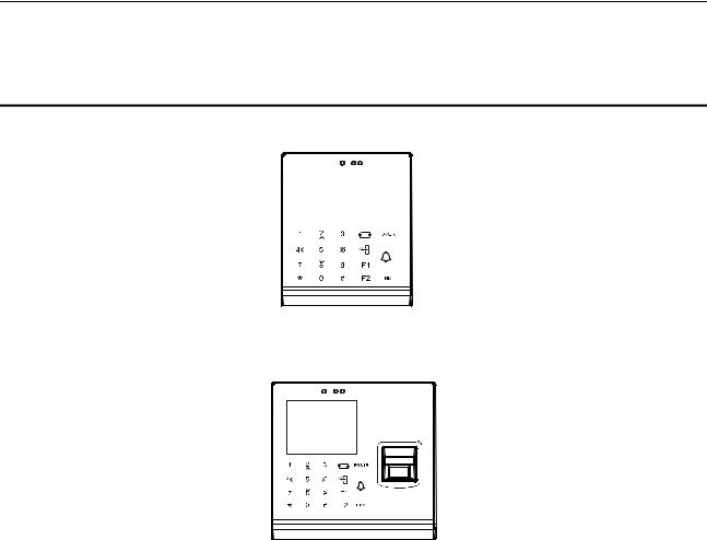
Figure 1-1 DS-K1T105 Series Standalone Access Control Terminal Front Panel
DS-K1T105 is a series of standalone access control terminal with picture capturing function. DS-K1T105 is designed with a 2.8-inch LCD display screen, and HD camera (2 MP optional). It supports two network communication methods (TCP/IP, and Wi-Fi), and supports offline operation.
Figure 1-2 DS-K1T200 Series IP-Based Fingerprint Access Control Terminal Front Panel
DS-K1T200 is a series optical IP-based fingerprint access control terminal with multiple advanced technologies including fingerprint recognition, face detection, Wi-Fi, smart card recognition, LCD display screen, and picture capturing technology. It is designed with a 2.8-inch LCD display screen, and HD camera (2 MP optional). It is equipped with optical fingerprint recognition module (supporting 1:1 mode and 1:N mode), and supports offline operation.
1.2 Main Features
1.2.1 Main Features of DS-K1T105 Series Model
Doorbell ringtone settings function
Touch mode and blue light display technique for keypad
Stand-alone settings for the terminal
2.8-inch LCD display screen
Transmission modes of wired network (TCP/TP) and Wi-Fi
Face detection and picture capturing function implemented by built-in camera (2 MP optional, only supports DS-K1T105E/M -C)
Supports multiple door opening modes (card, card + password, exit button, etc.)
Supports RS-485 communication for connecting to external card reader
Supports working as a card reader, and supports Wiegand interface and RS-485 interface for accessing the controller
Max. 100,000 valid card No., and Max. 300,000 access control events records storage
Supports EM card reading (DS-K1T105E/E-C)
Supports Mifare card reading, including card No. reading, & writing function (DS-K1T105M/M-C)
Tampering detection, unlocking overtime alarm, invalid card swiping over times alarm, and duress card alarm
Accurate data and time display provided by built-in electronic clock and watchdog program to ensure the basic function of the terminal
3

Access Control Terminal·User Manual
Data can be permanently saved after power-off
1.2.2 Main Features of DS-K1T200 Series Model
Doorbell ringtone settings function
Touch mode and blue light display technique for keypad
Stand-alone settings for the terminal
2.8-inch LCD display scree
Transmission modes of wired network (TCP/TP) and Wi-Fi
Face detection and picture capturing function implemented by built-in camera (2 MP optional, only supports DS-K1T200EF/MF-C)
Supports RS-485 communication for connecting external card reader
Supports working as a card reader, and supports Wiegand interface and RS-485 interface for accessing the controller
Max. 100,000 card No., Max. 300,000 access control events records , and Max. 9500 fingerprints storage
Adopts the optical fingerprint module, supporting 1:N mode (fingerprint, card + fingerprint) and 1:1 mode (card + fingerprint)
Supports multiple authentication modes (card, fingerprint, card + fingerprint, card + password, fingerprint + password, card + fingerprint + password, and so on.)
Supports EM card reading (DS-K1T200EF/EF-C)
Supports Mifare card reading, including card No. reading, and sector reading & writing (DS-K1T200MF/MF-C)
Tampering detection, unlocking overtime alarm, invalid card swiping over times alarm, duress card alarm, and so on
Accurate data and time display provided by built-in electronic clock and watchdog program to ensure the basic function of the terminal
Data can be permanently saved after power-off.
4
Access Control Terminal·User Manual
2 Appearance
2.1 Appearance of DS-K1T105 Series Model
Please refer to the following content for detailed information of the DS-K1T105 series model.
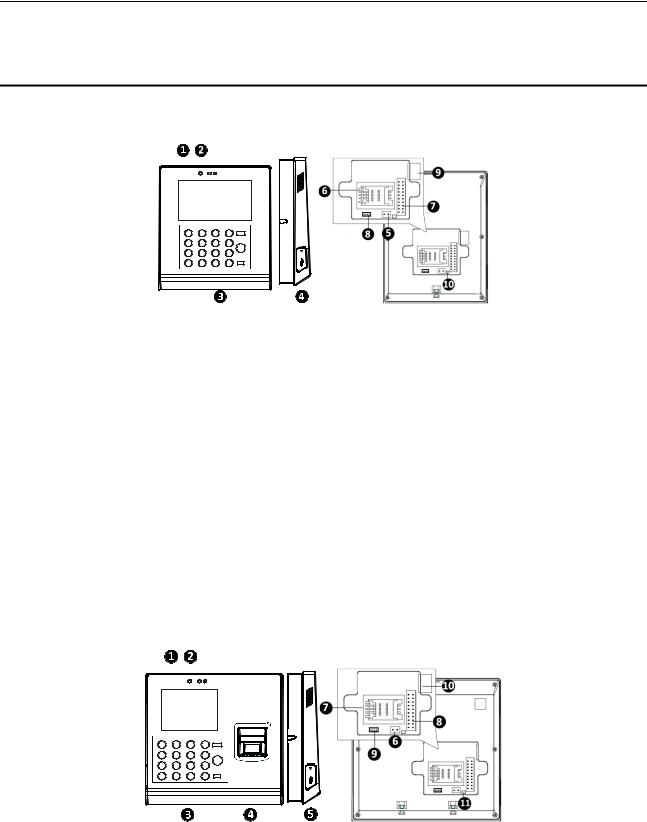
Figure 2-1 Appearance of DS-K1T105 Series Model
Table 2-1 Description of DS-K1T105 Series Model
No. |
Description |
1 |
2.8-Inch LCD Display Screen |
|
|
2 |
HD Camera with 2 MP (only DS-K1T105E/M/ -C |
|
support) |
|
|
3 |
Keypad |
|
|
4 |
USB 2.0 Interface |
|
|
5 |
Power Interface |
|
|
6 |
PSAM Card Slot |
|
|
7 |
External Wiring Terminals |
|
|
8 |
Serial Port |
|
|
9 |
Ethernet Port |
|
|
10 |
Tampering Prevention Switch |
|
|
2.2 Appearance of DS-K1T200Series Model
Please refer to the following content for detailed information of DS-K1T200 series model
Figure 2-2 Appearance of DS-K1T200 IP-Based Fingerprint Access Control Terminal
2.2.1 Description of Components
Table 2-2 DS-K1T200 IP-Based Fingerprint Access Control Terminal Components
No. |
Description |
1 |
2.8-Inch LCD Display Screen |
|
|
5
Access Control Terminal·User Manual
No. |
Description |
2 |
HD Camera with 2 MP (only DS-K1T200EF/MF |
|
-C support) |
|
|
3 |
Keypad |
|
|
4 |
Optical Fingerprint Reading Module |
|
|
5 |
USB 2.0 Interface |
|
|
6 |
Power Interface |
|
|
7 |
PSAM Card Slot |
|
|
8 |
External Wiring Terminals |
|
|
9 |
Serial Port |
|
|
10 |
Ethernet Port |
|
|
11 |
Tampering Prevention Switch |
|
|
2.3 Appearance of Keys
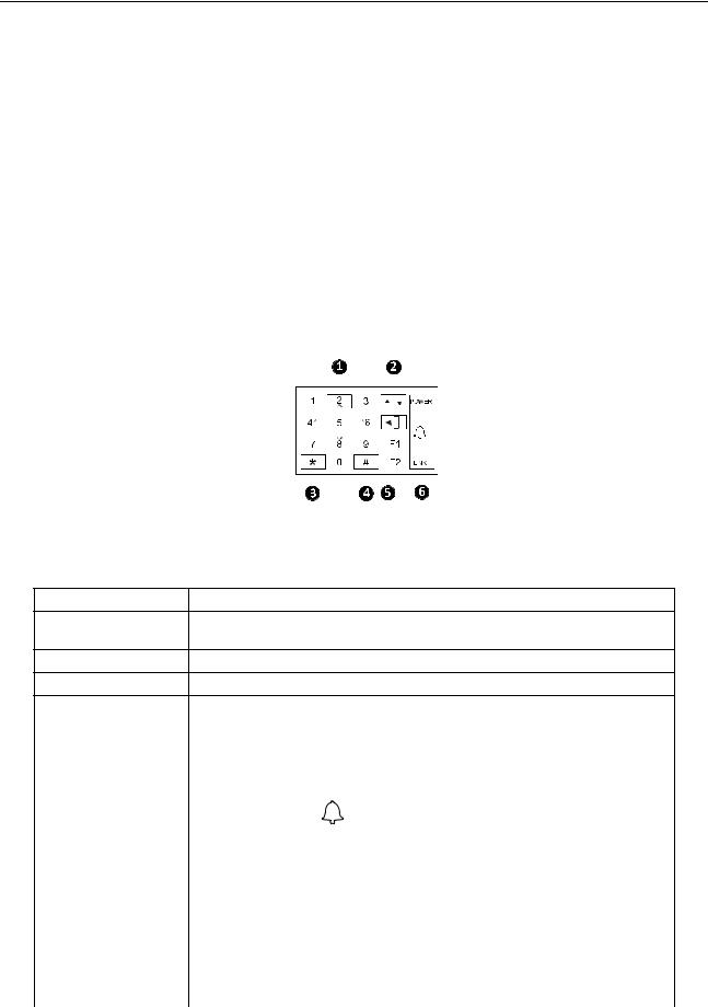
Figure 2-3 Appearance of Keys
2.3.1 Description of Items
Table 2-3 Description of Keys
No. |
Description |
|
|
1Numeric Keys: Enter number in the textbox. Direction Keys: Select icons in the menu.
2Editing Key: Click the key to enter/exit the editing status.
3Exiting Key: Click the key to exit the menu.
4Confirming Key: Click the key to confirm operations.
|
Long-click the key to enter the login interface. |
|||
|
|
|
|
|
5 |
Deleting Key: Click the key to delete contents in the textbox. |
|||
|
|
|
|
|
6 |
|
POWER |
Power Status |
Solid Blue: Normal Power. |
|
|
Off Power Exception. |
||
|
|
|
|
|
|
|
|
|
|
|
|
|
Doorbell Ring |
|
|
|
|
|
|
|
|
|
Normal Card/ |
Normal Card: Solid Blue |
|
Status Indicator: |
|
Illegal Card |
Illegal Card: Solid Red |
|
Indicator for power, |
|
|
Off: Network or Wi-Fi |
|
ring, and |
|
|
|
|
|
|
disconnected. |
|
|
connection status |
|
|
|
|
|
|
|
|
|
LINK |
|
Solid Blue: Network or Wi-Fi |
|
|
|
|
||
|
|
Connection |
connected, but client unarmed. |
|
|
|
|
||
|
|
|
Status |
Flicker Blue: Network or Wi-Fi |
|
|
|
|
connected, but client armed. |
|
|
|
|
|
|
|
|
|
Flicker blue in the card reader |
|
|
|
|
mode. |
|
|
|
|
|
6
Access Control Terminal·User Manual
Note: In the Event Card Interact interface in the iVMS-4200 Client Software, choose the alarm output of Event Bell. You can connect a bell at the alarm output terminal. For details about configuring the Event Bell alarm output, see the User Manual of iVMS4200 Client Software.
7

Access Control Terminal·User Manual
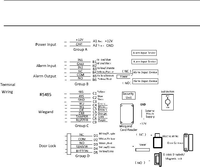
3 Terminal Connection
3.1 Terminal Description
Figure 3-1 Terminal Diagram of Access Control Terminal
8

Access Control Terminal·User Manual
Table 3-1 Terminal Description
|
Line Group |
|
|
No. |
|
|
Function |
|
|
Color |
|
|
Terminal |
|
|
Description |
|
|
|
|
|
|
|
|
|
|
Name |
|
|
|
|||||
|
|
|
|
|
|
|
|
|
|
|
|
|
|
|
|
|
|
|
Line Group A |
|
A1 |
|
Power Input |
|
Red |
|
+12V |
|
12V DC Power Supply |
||||||
|
|
|
|
|
|
|
|
|
|
|
|
|
|
||||
|
|
|
|
A2 |
|
|
|
|
Black |
|
GND |
|
GND |
||||
|
|
|
|
|
|
|
|
|
|
|
|
|
|
||||
|
|
|
|
B1 |
|
|
|
|
Yellow/Blue |
|
IN1 |
|
Alarm Input 1 |
||||
|
|
|
|
|
|
Alarm Input |
|
|
|
|
|
|
|||||
|
|
|
|
B2 |
|
|
Yellow/Black |
|
GND |
|
GND |
||||||
|
|
|
|
|
|
|
|
|
|
|
|
|
|
||||
|
Line Group B |
|
B3 |
|
|
|
|
Yellow/Orange |
|
IN2 |
|
Alarm Input 2 |
|||||
|
|
|
|
|
|
|
|
|
|
|
|
|
|
|
|
||
|
|
|
|
B4 |
|
|
|
|
Yellow/Purple |
|
NC |
|
|
|
|||
|
|
|
|
|
|
|
|
|
|
|
|
|
|||||
|
|
|
|
B5 |
|
Alarm Output |
|
Yellow/Brown |
|
COM |
|
Alarm Output Wiring |
|||||
|
|
|
|
|
|
|
|
|
|
|
|
|
|
|
|||
|
|
|
|
B6 |
|
|
|
|
Yellow/Red |
|
NO |
|
|
|
|||
|
|
|
|
|
|
|
|
|
|
|
|
|
|
|
|||
|
|
|
|
C1 |
|
RS-485 |
|
Yellow |
485 + |
|
|
|
|
||||
|
|
|
|
|
|
|
|
|
|
|
|
|
|
|
|
||
|
|
|
|
C2 |
|
Communication |
|
Blue |
485 - |
|
|
RS-485 Wiring |
|||||
|
|
|
|
|
|
|
Port |
|
|
|
|
|
|
|
|
|
|
|
|
|
|
C3 |
|
|
Black |
|
GND |
|
|
|
|||||
|
|
|
|
|
|
|
|
|
|
|
|
||||||
|
|
|
|
|
|
|
|
|
|
|
|
|
|
||||
|
|
|
|
C4 |
|
|
|
|
Green |
|
W0 |
|
Wiegand Wiring 0 |
||||
|
|
|
|
|
|
|
|
|
|
|
|
|
|
||||
|
|
|
|
C5 |
|
|
|
|
White |
|
W1 |
|
Wiegand Wiring 1 |
||||
|
Line Group C |
|
|
|
|
|
|
|
|
|
|
|
|
|
|
|
|
|
|
C6 |
|
|
|
|
Brown |
|
WG_OK |
|
Wiegand Authenticated |
||||||
|
|
|
|
|
|
|
|
|
|
||||||||
|
|
|
|
|
|
|
Wiegand |
|
|
|
|
|
|
|
|
|
|
|
|
|
|
C7 |
|
|
Orange |
|
WG_ERR |
|
Wiegand |
||||||
|
|
|
|
|
|
|
|
|
|
||||||||
|
|
|
|
|
|
|
|
|
|
Authentication Failed |
|||||||
|
|
|
|
|
|
|
|
|
|
|
|
|
|
|
|
||
|
|
|
|
|
|
|
|
|
|
|
|
|
|
|
|
|
|
|
|
|
|
C8 |
|
|
|
|
Grey |
|
TAMPER |
|
Tampering Alarm |
||||
|
|
|
|
|
|
|
|
|
|
Wiring |
|||||||
|
|
|
|
|
|
|
|
|
|
|
|
|
|
|
|
||
|
|
|
|
|
|
|
|
|
|
|
|
|
|
||||
|
|
|
|
C9 |
|
|
|
|
Purple |
|
BUZZER |
|
Buzzer Wiring |
||||
|
|
|
|
|
|
|
|
|
|
|
|
|
|
|
|||
|
|
|
|
D1 |
|
|
|
|
White/Purple |
|
NC |
|
|
|
|||
|
|
|
|
|
|
|
|
|
|
|
|
|
Lock Wiring |
||||
|
|
|
|
D2 |
|
|
|
|
White/Yellow |
|
COM |
|
|||||
|
|
|
|
|
|
|
|
|
|
|
|
|
|
|
|||
|
Line Group D |
|
D3 |
|
Lock |
|
White/Red |
|
NO |
|
|
|
|||||
|
|
|
|
|
|
|
|
|
|
|
|
|
|
||||
|
|
|
|
D4 |
|
|
|
|
Yellow/Green |
|
SENSOR |
|
Door Contact Signal |
||||
|
|
|
|
|
|
|
|
|
|
Input |
|||||||
|
|
|
|
|
|
|
|
|
|
|
|
|
|
|
|
||
|
|
|
|
|
|
|
|
|
|
|
|
|
|
||||
|
|
|
|
D5 |
|
|
|
|
Yellow/Grey |
|
BUTTON |
|
Exit Door Wiring |
||||
|
|
|
|
|
|
|
|
|
|
|
|
|
|
|
|
|
|
9
Access Control Terminal·User Manual
4 Wiring Description
4.1 External Device Wiring Overview
Figure 4-1 External Device Connection Diagram
10

Access Control Terminal·User Manual
4.2 The Wiring of External Card Reader
4.2.1 The Wiring of External RS-485 Card Reader
Figure 4-2 External RS-485 Card Reader Connection Diagram
4.2.2 The Wiring of External Wiegand Card Reader
Figure 4-3 External Wiegand Card Reader Connection Diagram
Notes:
Set the dial-up of the external card reader as 2 when connected to the access control terminal.
The external power supply and the access control terminal should use the same GND cable.
11
Access Control Terminal·User Manual
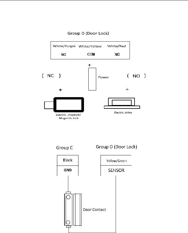
4.3 The Wiring of Electric Lock and Door Contact
4.3.1 The Wiring of Electric Lock
Figure 4-4 The Installation of Electric Dropbolt, Magnetic Lock, and Electric Strike
Note: Signal input interface of the door status (DOOR_NC, DOOR_COM, DOOR_NO) is used to recognize whether the door is locked. If the NC interface is connected for opening door, the NO interface can only be connected for locking door.
4.3.2 The Wiring of Door Contact
Figure 4-5 The Installation of Door Contact
12
Access Control Terminal·User Manual
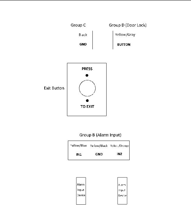
4.4 The Wiring of Exit Button
Figure 4-6 The Installation of Exit Button
4.5 The Wiring of Alarm Input
Figure 4-7 Alarm Input Connection
13
Access Control Terminal·User Manual
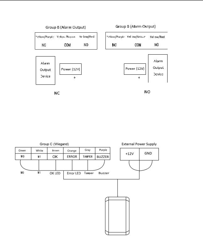
4.6 The Wiring of External Alarm Device
Figure 4-8 The Installation Diagram of External Alarm Device
4.7 Card Reader Connection
The access control terminal can be switched into the card reader mode. It can access to the access control as a card reader, and supports Wiegand communication port and RS-485 communication port.
Note: When the access control terminal works as a card reader, it only supports being connected to the controller, but does not support alarm input or output, or the connection of external devices.
4.7.1 The Wiring of Wiegand
Figure 4-9 Wiegand Connection Diagram
Notes:
When the access control terminal works as a card reader, you must connect the WG_ERR, BUZZER and WG_OK interfaces if you want to control the LED and buzzer of the Wiegand card reader.
Set the working mode of the terminal as card reader, which can be configured in System Parameter –> Mode Switch, if the terminal is required to work as a card reader. The card reader mode support to communicate by Wiegand or RS-485.
The distance of Wiegand communication should be no longer than 80 m.
The external power supply and the access control terminal should use the same GND cable.
14
Access Control Terminal·User Manual
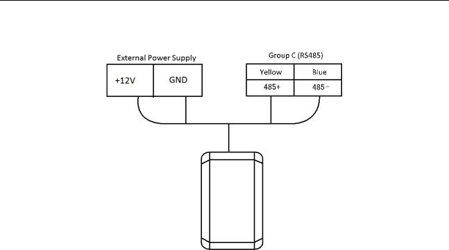
4.7.2 The Wiring of RS-485 Output
Figure 4-10 RS-485 Connection Diagram
Notes:
Set the working mode of the terminal as card reader, which can be configured in System Parameter –> Mode Switch, if the terminal requires working as a card reader.
When the access control terminal works as a RS-485 card reader, the default RS-485 address is 1. RS-485 address can also be configured in System Parameter -> Serial Port Settings.
The external power supply and the access control terminal should use the same GND cable.
15

Access Control Terminal·User Manual
5 Activating the Access Control Terminal
Purpose:
You are required to activate the terminal first before using it.
Activation via SADP, and Activation via client software are supported.
The default values of the control terminal are as follows.
The default IP address: 192.0.0.64.
The default port No.: 8000.
The default user name: admin.
5.1 Activating via SADP Software
SADP software is used for detecting the online device, activating the device, and resetting the password.
Get the SADP software from the supplied disk or the official website, and install the SADP according to the prompts. Follow the steps to activate the control panel.
Steps:
1.Run the SADP software to search the online devices.
2.Check the device status from the device list, and select an inactive device.
Figure 5-1 SADP Interface
3.Create a password and input the password in the password field, and confirm the password.
STRONG PASSWORD RECOMMENDED– We highly recommend you create a strong password of your own choosing (using a minimum of 8 characters, including upper case letters, lower case letters, numbers, and special characters) in order to increase the security of your product. And we recommend you reset your password regularly, especially in the high security system, resetting the password monthly or weekly can better protect your product.
4.Click OK to save the password.
You can check whether the activation is completed on the pop-up window.
If activation failed, please make sure that the password meets the requirement and then try again.
5.Change the device IP address to the same subnet with your computer by either modifying the IP address manually or checking the checkbox of Enable DHCP.
16
Access Control Terminal·User Manual
Figure 5-2 Modify Network Parameters Interface
6.Input the password and click the Save button to activate your IP address modification.
5.2 Activating via Client Software
The client software is versatile video management software for multiple kinds of devices.
Get the client software from the supplied disk or the official website, and install the software according to the prompts. Follow the steps to activate the control panel.
Steps:
1.Run the client software and the control panel of the software pops up, as shown in the figure below.
2.Click the  icon on the upper-left side of the page, select Access Control to enter the control panel.
Figure 5-3 Control Panel Interface
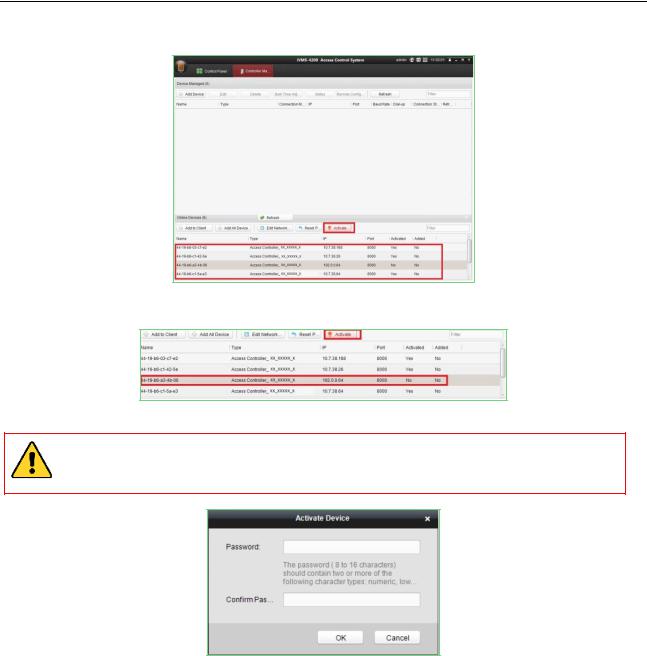
3.Click the Controller Management icon to enter the Controller Management interface, as shown in the figure below.
17
Access Control Terminal·User Manual
Figure 5-4 Device List
4.Check the device status from the device list, and select an inactive device.
5.Click the Activate button to pop up the Activation interface.
Figure 5-5 List Selecting Interface
6.Create a password and input the password in the password field, and confirm the password.
STRONG PASSWORD RECOMMENDED– We highly recommend you create a strong password of your own choosing (using a minimum of 8 characters, including upper case letters, lower case letters, numbers, and special characters) in order to increase the security of your product. And we recommend you reset your password regularly, especially in the high security system, resetting the password monthly or weekly can better protect your product.
7.Click OK button to start activation.
8.Click the  button to pop up the Network Parameter Modification interface.
9.Change the device IP address to the same subnet with your computer by either modifying the IP address manually or checking the checkbox of Enable DHCP.
10.Input the password to activate your IP address modification.
18
Access Control Terminal·User Manual
6 Basic Operation
Before You Start:
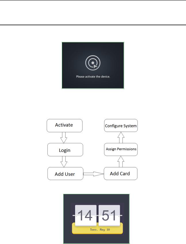
You should activate the device before the first login. Otherwise, after powered on, the system will switch into activate notifying interface. For detailed information about activation, see Chapter 5 Activating the Access Control Terminal.
Figure 6-1 Activation Notifying Interface
You should enter the default password for the first login.
Enter System Settings -> System Parameter –> Login Password to reset the login password.
The default password is 12345.
The working flow is as follows:
Steps:
1.Power on the device to enter the initial interface.
Figure 6-2 Initial Interface
2.Long-click the # key to enter the password authentication interface.
19
Access Control Terminal·User Manual
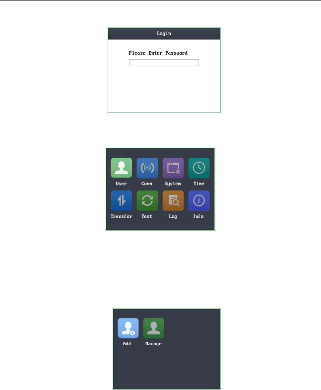
Figure 6-3 Password Authentication Interface
3.Enter the default configuration password.
Tap the # key to confirm the settings. If the configuration password authentication failed, the system will return to the initial interface, and if the configuration password is successfully authenticated, the system will enter the menu operation interface
Figure 6-4 Menu Operation Interface
On the menu operation interface, you can manage users, set communication parameters, set system parameters, and so on.
6.1 User Management
Purpose:
On the user management interface, you can add and manage users.
Steps:
1.Move the cursor to User (user management) with the direction keys.
2.Tap the # key to enter the user management interface.
Figure 6-5 User Management Interface
6.1.2 Adding User
Purpose:
In the Adding User menu, you can add users, register card, and record fingerprints optionally for the corresponding person.
Steps:
1.Move the cursor to Add (add user) by using the direction keys.
2.Tap the # key to enter the card registration interface.
20
Access Control Terminal·User Manual
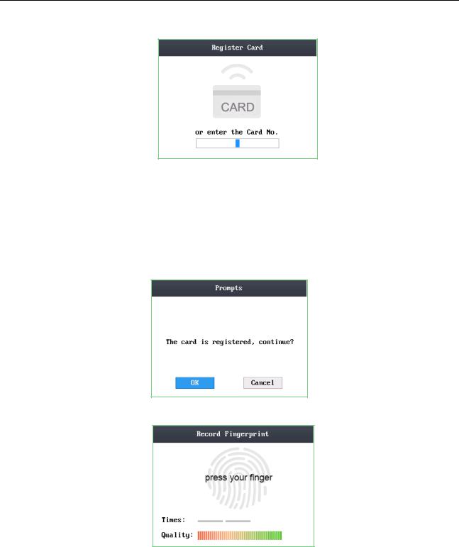
Figure 6-6 Card Registration Interface
3.Register the card.
Register the card by swiping the card.
1)Place the card on the induction area.
2)The system displays the card No. in the textbox automatically with a beep sound if the card No. has been recognized. .
Register the card by entering the card number into the or enter the Card No. textbox.
1)Tap the 
 key to enter the editing mode.
2)Enter the card number into the textbox.
3)Tap the 
 key to exit the editing mode.
4.After registering the card, a dialog box about whether to register the fingerprint pops up.
Figure 6-7 Card Registration PoP-Up Window
1)Move the cursor to the OK button, and tap the # key to enter the fingerprint registration interface.
Figure 6-8 Fingerprint Registration Interface
2) Place the finger on the fingerprint scanner, rise and rest your finger by following the corresponding voice prompts.
Notes:
The fingerprint registration function only supports device with fingerprint module.
The same fingerprint cannot be repeatedly registered.
For the optical access control terminal, you should place your finger twice to register the fingerprint. For details about scanning the fingerprint, see Appendix.
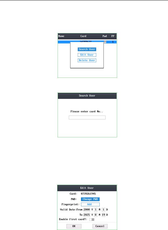
6.1.2 Managing User
1.Move the cursor to Manage (edit user) by using direction keys on the user management interface.
2.Tap the # key to enter the managing user interface.
21
Access Control Terminal·User Manual
Searching User
Steps:
1.Move the cursor to a user by using direction keys.
2.Tap the # key to pop up an interface for selecting corresponding operations.
Figure 6-9 Managing User Interface
3.Move the cursor to Search User.
4.Tap the # key to enter the searching interface.
Figure 6-10 Searching Interface
5.Enter the card number into Please enter card No. textbox.
6.Tap the # key to view the basic information about the card holder.
Editing User
Steps:
1.Move the cursor to a user by using direction keys.
2.Click the # key to popup an interface for selecting corresponding operations. (Figure 6-9)
3.Move the cursor to Editing User.
4.Tap the # key to enter the editing interface.
Figure 6-11 Editing Interface
5.Edit the user information.
Adding the Fingerprint
22
Access Control Terminal·User Manual
Move the cursor to Add to enter the fingerprint registration interface. See details in step 4 of adding user. Note: DS-K1T105 series model does not support this function.
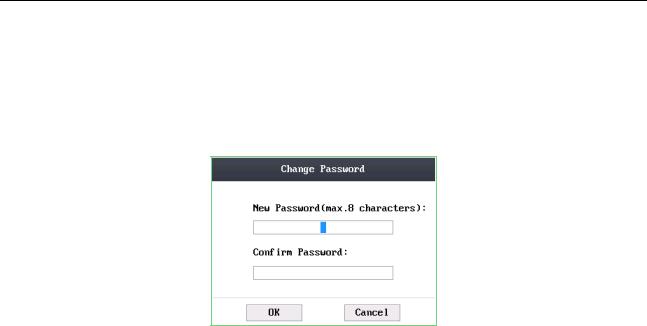
Changing the Password
1)Move the cursor to Change PWD to enter the password changing interface.
2)Enter a new password.
3)Confirm the new password.
Figure 6-12 Password Changing Interface
Changing the valid date
You can set the start/end time of the user’s permission.
Click the 
 key to enter/exit the editing mode.
Enabling first card
Tap the # key to enable first card.
Note: After enabling first card, the door remains open during the pre-defined valid duration.
6.Move the cursor to the OK button, and click the # key to confirm the settings.
Deleting the User
Steps:
1.Move the cursor to the user by using direction keys.
2.Tap the # key to pop up an interface for selecting corresponding operations. (Figure 6-9)
3.Move the cursor to Delete User, and tap the # key to enter the deleting interface.
4.Move the cursor to Delete User, Delete PWD only or Delete FP only,.
Delete User: Delete the user and the overall information. Delete PWD only: Only delete the password set by the user.
Delete FP only: Only delete the fingerprint information of the user. Note: DS-K1T105 series model does not support this function.
5.Tap the # key to finish the deleting operation.
Note: You can tap * key to return to the main menu.
6.2 Communication Settings
Purpose:
On the communication settings interface, you can set network parameters, the serial port, Wiegand parameters, and Wi-Fi.
Steps:
1.Move the cursor to Comm (communication settings) by using direction keys.
2.Tap the # key to enter the communication settings interface.
23

Access Control Terminal·User Manual
Figure 6-13 Communication Settings Interface
Network Settings: It refers to network parameters of the device, including IP address, subnet mask, and gateway address.
Serial Port Settings: When the access control terminal works as a RS-485 card reader, serial port parameters include working mode, Baud Rate, and RS-485 address.
Wiegand Settings: When the access control terminal works as a Wiegand card reader, Wiegand parameters involve the Wiegand direction, and the Wiegand mode.
Wi-Fi: You can enable the Wi-Fi function.
6.2.1 Network Settings
Purpose:
On the network settings interface, you can set network parameters of the device.
Steps:
1.Move the cursor to Network (network settings) by using direction keys.
2.Tap the # key to enter the network settings interface.
Figure 6-14 Network Settings Interface
3.Modify network parameters of the device, including IP address, subnet mask, and gateway address. Note: Tap the 
 key to enter/exit the editing mode.
4.Move the cursor to the OK button, and tap the # key.
6.2.2 Serial Port Settings
Purpose:
When the access control terminal works as the RS-485 card reader, you should set serial port parameters.
Steps:
1.Move the cursor to Serial (serial port settings) by using direction keys on the communication settings interface.
2.Tap the # key to enter the serial port settings interface.
24

Access Control Terminal·User Manual
Figure 6-15 Serial Port Settings Interface
3.Modify parameters of the serial port, including working mode, Baud Rate, and RS-485 address.
Working Mode: When the access control terminal works as the terminal, you can connect it to Card Reader, Client Software and Control Unit.
Notes:
Set the working mode of the serial port as Connect to Card Reader if the access control terminal is connected to the external card reader.
If the terminal is worked as the card reader, Working Mode cannot be used.
Baud Rate: It will display the Baud Rate configured on the client software.
RS-485 Address: When the access control terminal works as a card reader, the RS-485 address should be configured.
Notes:
Tap the 
 key to enter and exit the editing mode.
Tap the Right/Left direction keys to choose contents.
Tap the # key to switch the mode between “Yes” mode and “No” mode.
4.Move the cursor to the OK button, and tap the # key. Note: Reboot the device after changing the working mode.
6.2.3 Wiegand Settings
Purpose:
When the access control terminal works as the Wiegand card reader, you should set Wiegand parameters.
Steps:
1.Move the cursor to Wiegand (Wiegand settings) by using direction keys on the communication settings interface.
2.Tap the # key to enter the Wiegand settings interface.
Figure 6-16 Wiegand Settings Interface
3. Edit parameters of the serial port, including the Wiegand direction, and the Wiegand mode.
Wiegand Direction:
1)In the terminal mode, select whether to Receive or to Send. In the Receive mode, the mode cannot be changed.
2)In the card reader mode, only Send is supported.
Wiegand Mode: The default Wiegand mode is Wigand 34.
Notes:
Tap the 
 key to enter and exit the editing mode.
Tap the Right/Left direction keys to choose contents.
Tap the # key to switch the mode between “Yes” mode and “No” mode.
25

Access Control Terminal·User Manual
4.Move the cursor to the OK button, and tap the # key. Note: Reboot the device after changing the Direction.
6.2.4 Wi-Fi Settings
Steps:
1.Move the cursor to Wi-Fi (Wi-Fi settings) by using direction keys on the communication settings interface.
2.Tap the # key to enter the Wi-Fi settings interface.
Figure 6-17 Wi-Fi Enabling
3.Move the cursor to  and tap the # key to enable the WLAN.
Figure 6-18 Wi-Fi Selection
4.Move the cursor to a network, and tap # key to enter the network connection interface.
Figure 6-19 Wi-Fi Settings
5.Enter the password of the network. The password supports numbers, letters (uppercase and lowercase) and symbols.
6.Edit the IP mode, IP address, subnet mask, and gateway address.
7.Move the cursor to the OK button, and tap the # key.
Note: Tap the 
 key to enter and exit the editing mode.
6.3 System Settings
Purpose:
On the system settings interface, you can set system parameters, manage the data, restore default settings, set access control parameters, and set cameras.
26
 Loading...