


1
DS-8700 Series Net DVR
User Manual
V2.2
Thank you for purchasing our embedded Net DVR. This manual is applicable for
DS-8700 series Net DVR. Please read this User Manual carefully to ensure that you can
use the device correctly and safely.
The contents of this Manual are subject to change without notice.

2
Index
Safety Precaution .............................................................................................................................. 5
Chapter1 Product Introduction.................................................................................................. 8
1.1 Summary ................................................................................................................... 8
1.2 Model Description ..................................................................................................... 8
1.3 Features ..................................................................................................................... 9
1.4 Typical Application ................................................................................................. 11
Chapter2 Installation ............................................................................................................... 12
2.1 Check DVR and It’s Accessories ............................................................................ 12
2.2 HDD Installation ..................................................................................................... 12
2.3 DVR Rear Panel ...................................................................................................... 15
2.4 External Alarm In/Out Connection ......................................................................... 16
2.5 Powering up ............................................................................................................ 17
Chapter3 Operational Instructions .......................................................................................... 18
3.1 DVR Front Panel ..................................................................................................... 18
3.2 IR Control ............................................................................................................... 20
3.3 OSD Menu Description ........................................................................................... 22
3.3.1 Main Menu Items ............................................................................................ 22
3.3.2 Menu Operation .............................................................................................. 23
3.4 Character Input ........................................................................................................ 26
Chapter4 Basic Operation Guide ............................................................................................ 27
4.1 Power on ................................................................................................................. 27
4.2 Live View ................................................................................................................ 28
4.3 Login ....................................................................................................................... 32
4.4 PTZ Control ............................................................................................................ 33
4.5 Manual Record ........................................................................................................ 35
4.6 Playback .................................................................................................................. 37
4.7 Backup Recorded Files ........................................................................................... 44
4.8 Turn off DVR .......................................................................................................... 48
Chapter5 Advanced Operation Guide ..................................................................................... 50
5.1 User Management ................................................................................................... 51
5.1.1 Add User ......................................................................................................... 52
5.1.2 Delete User ...................................................................................................... 54
5.1.3 Password Modification .................................................................................... 55
5.1.4 User Rights ...................................................................................................... 57
5.2 Device ID and Language ......................................................................................... 60
5.3 Video Standard and VGA Setup .............................................................................. 61
5.4 Day and Time Setup ................................................................................................ 63
5.4.1 Day and Time Setting ...................................................................................... 63
5.4.2 Day and Time Display Mode .......................................................................... 64
5.5.3 Daylight Saving Time Setup ........................................................................... 66
5.5 Camera Setup .......................................................................................................... 67

3
5.5.1 Camera Name Setup ........................................................................................ 67
5.5.2 Video Parameters Setup .................................................................................. 68
5.6 Mask Area Setup ..................................................................................................... 70
5.7 View Tampering Alarm ........................................................................................... 72
5.8 Video Loss Alarm .................................................................................................... 74
5.9 Motion Detection Alarm ......................................................................................... 76
5.10 Live View Setup ...................................................................................................... 80
5.11 Recording Setup ...................................................................................................... 83
5.12 Alarm I/O Setup ...................................................................................................... 88
5.13 Network Setup......................................................................................................... 93
5.13.1 Network Basic Settings ................................................................................... 93
5.13.2 Network Advanced Settings ............................................................................ 94
5.13.3 DHCP Function ............................................................................................... 94
5.13.4 PPPoE Function .............................................................................................. 95
5.13.5 IP Server Solution for DHCP .......................................................................... 96
5.13.6 DDNS setup ......................................................................................................... 97
5.13.7 Email setup ........................................................................................................... 97
5.14 PTZ Setup ............................................................................................................... 97
5.14.1 PTZ Connection .............................................................................................. 98
5.14.2 PTZ Settings .................................................................................................... 98
5.14.3 PTZ Control .................................................................................................. 100
5.14.4 Preset Setup ................................................................................................... 100
5.14.5 Sequence Setup ............................................................................................. 101
5.14.6 Tour Setup ..................................................................................................... 103
5.15 RS232 Setup .......................................................................................................... 104
5.15.1 Console Mode ............................................................................................... 104
5.15.2 Transparent Channel Mode ........................................................................... 104
5.16 Exceptions Setup ................................................................................................... 104
Chapter6 Utilities .................................................................................................................. 106
6.1 Restore Parameters ................................................................................................ 107
6.2 Hard Disk Management ........................................................................................ 108
6.3 Clear Alarm Out .................................................................................................... 108
6.4 Reboot ................................................................................................................... 108
6.5 Power Off .............................................................................................................. 108
6.6 View Log ............................................................................................................... 109
6.7 System Information ............................................................................................... 112
6.8 Multi-Playback ...................................................................................................... 112
Chapter7 Firmware Upgrade ........................................................................................ 114
7.1 Upgrade from USB Flash ...................................................................................... 114
7.2 Upgrade from FTP Server ..................................................................................... 115
7.2.1 FTP Server Setup........................................................................................... 115
7.2.2 Use DVR FTP Upgrade Function.................................................................. 117
7.2.3 Use RS-232 Serial Command ....................................................................... 117
7.3 Use Client Software to Upgrade............................................................................ 120

4
Appendix A HDD Capacity Calculation ................................................................................... 121
Appendix B DVR Connector Definition ................................................................................... 122
1 RS485 Connecting ........................................................................................................ 122
2 UTP Network Connecting ............................................................................................. 123
3 RS232 Connecting ........................................................................................................ 125
Appendix C Specifications ........................................................................................................ 128
Appendix D Quick Search ......................................................................................................... 130
Appendix E Troubleshooting .................................................................................................... 132
Appendix F Product Service ..................................................................................................... 134
Appendix G Customer Information Card .................................................................................. 135

5
Safety Precaution
Caution:
To reduce the risk of electric shock, do not remove cover, (unless you wish to install
hard disks, please see the section "Hard Disk Installation").
No User-serviceable parts inside. Refer servicing to qualified service personnel.
Important Safeguards:
1. Read these instructions.
2. Keep these instructions.
3. Heed all warnings.
4. Follow all instructions.
5. Do not use this apparatus near water.
6. Clean only with a dry cloth.
7. Do not block any ventilation openings. Install in accordance with the manufacturer's
instructions.
8. Do not install near any heat sources such as radiators, heat registers, stoves, or other
apparatus (including amplifiers) that produce heat.
9. Do not defeat the safety purpose of the polarized or grounding-type plug. A polarized
plug has two blades with one wider than the other. A grounding-type plug has two
blades and a third grounding prong. The wide blade or third prong are provided for
your safety. If the provided plug does not fit into the outlet, consult an electrician for
replacement of the obsolete outlet.
10. Protect the power cord from being walked on or pinched particularly at plugs,
convenience receptacles, and the point where they exit from the apparatus.
11. Only use attachments/accessories specified by the manufacturer.
12. Use only with the cart, stand, tripod, bracket, or table specified by the manufacturer,
or sold with the apparatus. When a cart is used, use caution when moving the
cart/apparatus combination to avoid injury from tip-over.

6
13. Unplug this unit during lightning storms or when unused for long periods of time.
14. Refer all servicing to qualified service personnel. Servicing is required when the
apparatus has been damaged in any way, such as power-supply cord or plug is
damaged, liquid has been spilled or objects have fallen into the apparatus, the
apparatus has been exposed to rain or moisture, does not operate normally, or has
been dropped.
15. Moving - Disconnect the power before moving the unit. The unit should be moved with
care. Excessive force or shock may result in damage to the unit and the hard disk
drives.
16. Power Sources - This unit should be operated only from the type of power source
indicated on the marking label. If you are not sure of the type of power supply you
plan to use, consult your appliance dealer or local power company.
17. Overloading - Do not overload outlets and extension cords as this can result in a risk
of fire or electric shock.
18. Object and Liquid Entry - Never push objects of any kind into this unit through
openings, as they may touch dangerous voltage points or short out parts that could
result in a fire or electric shock. Never spill liquid of any kind on the unit.
19. Replacement Parts - When replacement parts are required, be sure the service
technician has used replacement parts specified by the manufacturer or have the
same characteristics as the original part. Unauthorized substitutions may result in fire,
electric shock, or other hazards.
20. Coax Grounding - If an outside cable system is connected to the unit, be sure the
cable system is grounded. U.S.A. models only--Section 810 of the National Electrical
Code, ANSI/NFPA No.70-1981, get information from professional electrician to proper
grounding of the mount and supporting structure, grounding of the coax to a
discharge unit, size of grounding conductors, location of discharge unit, connection to
grounding electrodes, and requirements for the grounding electrode.
21. To reduce the risk of fire or electric shock, this apparatus should not be exposed to
rain or moisture and objects filled with liquids, such as vases, should not be placed on
this apparatus.

7
22. Danger of explosion if battery is incorrectly replaced. Replace only with the same or
equivalent type. Dispose of the replaced battery in an environmentally friendly way.
Cleaning
You can clean the unit with a moist fluff-free cloth or shammy leather cloth.
Warning
This device is intended for use in public areas only. Surreptitious recording of oral
communications is may prohibited by law.
Unpacking
Check the package for visible damage. If any items appear to have been damaged in
shipment, notify the shipping company. Unpack carefully. This is electronic equipment and
should be handled with care to prevent damage to the unit. Do not attempt to use the unit
if any components are damaged. If any items are missing, notify the dealer.
The shipping carton is the safest container in which to transport the unit. Save it and
all packing materials for future use. If the unit must be returned, use the original packing
materials.
Packaging contents
The package should contain the following items:
1. Digital Video Recorder
2. Accessories box

8
DS - 87 xx H I
Oversea product
Model name (H)
Camera number
Embedded DVR code name
Digital Surveillance
Chapter1 Product Introduction
1.1 Summary
DS-8700HI series network digital video recorder is an excellent digital surveillance
product. It uses the embedded MCU and embedded operating system (RTOS), combining
the most advanced technology in Information Industry such as video and audio
encoding/decoding, hard disk record and TCP/IP. The firmware is burned in the flash,
more stable and reliable.
DS-8700 series device has both the features of digital video recorder (DVR) and
digital video server (DVS). It can work stand alone, also be used to build a powerful
surveillance network, widely used in bank, telecommunication, transportation, factories,
warehouse, irrigation, etc.
1.2 Model Description

9
1.3 Features
Compression
Support 16 channels video input (PAL/NTSC) at most. Each channel is
independent, H.264 hardware compression and real time (PAL: 25 FPS, NTSC:
30FPS). Support both variable bit rate and variable frame rate
Support 4 channels audio input at most. Each channel is independent,
OggVorbis compression and bit rate is 16Kbps
Compressed video and audio are synchronous. You can select either mixed
stream or only video stream
Support 4CIF, DCIF, 2CIF, CIF and QCIF resolution
Support multi area motion detection
Support OSD and changeable OSD position
Support LOGO and changeable LOGO position
Local functions
Record
Support multiple record type, including real time, manual record, motion
detection, external alarm, motion&alarm, motion|alarm
Support 4 SATA HDDs maximum and each HDD can support 2000GB maximum
Support FAT32 file system
Support HDD S.M.A.R.T technology
Support cycle or none cycle record
Support backup the recorded files and clips. Support USB memory, USB HDD,
USB CD/DVD, SATA CD/DVD writer for backup
Preview and playback
Support BNC analog monitor and VGA output for main output
Support multiple preview modes
Support Dual-stream
Support sensitive area mask

10
Support camera spiteful block alarm
Support multi-ch playback. Support play forward, backward, pause, frame by
frame, etc
Support play back by files or by time
Display local record status
PTZ
Support many kinds of PTZ protocol
Support preset, sequence and Tour
Alarms
Support exception alarm, motion detection alarm, external alarm, etc
Others
Support IR control
Support RS-485 keyboard
Support multi-level user management
Network
Support TCP, UDP, RTP, Multicast for network preview
Support PPPoE for board band dialup
Support remote parameters setup
Alarm information can be sent to remote center
Network control PTZ
Network record the real time stream
Network download and playback the recorded files in DVR
Remote upgrade the firmware
RS-232 supports transparent channel function so that the remote PC can use
DVR to control serial devices
Support bi-direction voice talk or one-way voice broadcast
Support IE to preview and configure DVR
11
Support log.
Development support
Provide network SDK
Provide client demo source code
USB-related function
Add USB device [Format], [New Folder], [Delete File] and [Backup] functions.
Backup segment, Multi-backup, all day backup (default in first divisional root
directory).
Record files in USB devices could be played.
Add log backup function.
Add device configuration backup function.
1.4 Typical Application
12
Chapter2 Installation
2.1 Check DVR and It’s Accessories
When you get the product, check that all the items are included in your product
package. There is a list in the package. If any of the items is missing, please contact your
dealer.
2.2 HDD Installation
Installing the hard disks must be done only by qualified personnel. Unauthorized
installation of hard disks may result in permanent damage of the disk and the recorder,
and is at own risk.
Caution:
When working with electrostatic sensitive devices such as a hard disk or the DVR unit,
make sure you use a static-free workstation. Any electrostatic energy coming in contact
with the hard disk or DVR main board can damage it permanently.
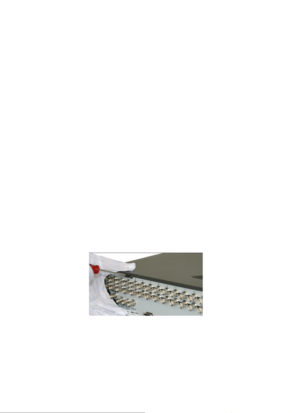
1: Loosen the Screws and open the metal cover.
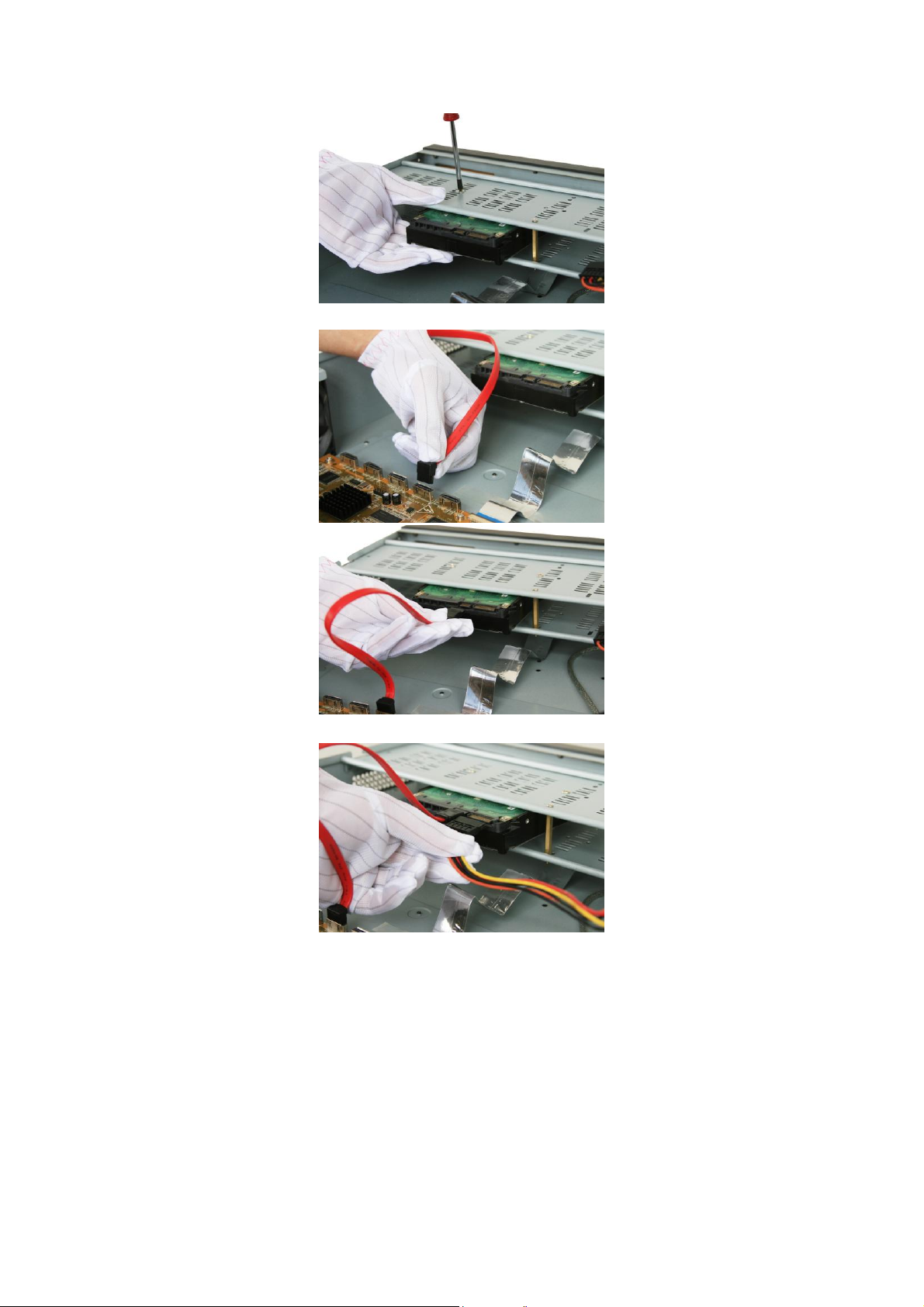
2:Fix the hard disk in bracket. If the hard disk is installed in underlayer, the uplayer
bracket should be removed firstly.
13
3:Connect the motherboard and hard disk by data cable.
4:Connect the power cable to hard disk.
5:Mount back the metal cover, and fixed by screws.
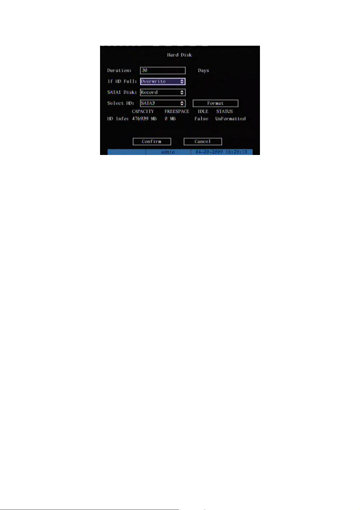
6: Press [MENU] key to enter into DVR main menu. Go to the "Utilities" menu and
choose "Hard disk" to format the hard disks, Check if all installed disks are detected by
the DVR, and if the capacity is OK. Choose "Format" and select "All" to format all hard
disks. When all disks are formatted a confirmation message will be shown on the
screen. Check if all installed disks have the status "OK".
14
The installation of HDD is complete.
15
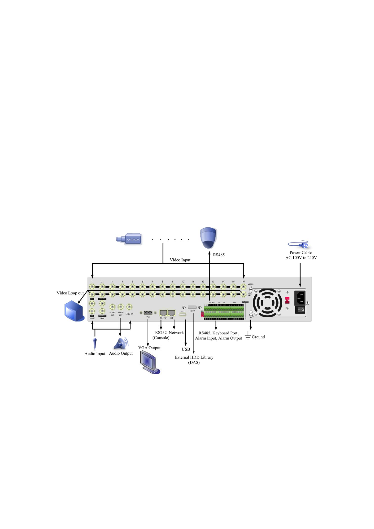
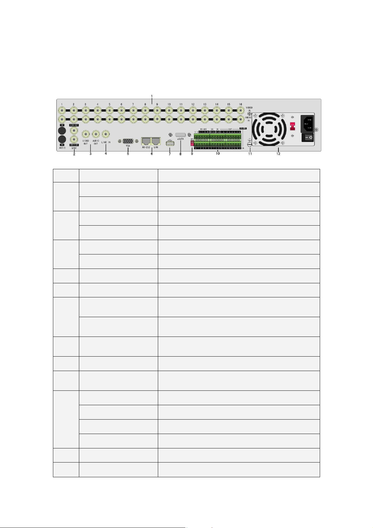
2.3 DVR Rear Panel
Index
Physical Interface
Description
1
Video input
Standard BNC
Audio Input
Standard BNC
2
Spot video output
Spot monitor for live video and playback
Spot audio output
Spot monitor for live audio and playback
3
Main video output
Main monitor for live video playback and menu
Main audio output
Main monitor for live audio and playback
4
Line in
Line input for audio
5
VGA interface
VGA display
6
RS-232
Connect RS-232 devices. Refer to Appendix B for pin
definition
Network interface
Connect network devices. Refer to Appendix B for pin
definition
7
USB Interface
USB flash memory, USB HDD, USB CD/DVD or USB
mouse
8
E-SATA
Optional. Extend 1st internal SATA to E-SATA.
9
SW1
RS-485 terminal resistor switch. Default is off. The
resistor is 120Ω
10
RS-485
PTZ connection. Using T+/T- to connect PTZ.
Keyboard interface
Using D+/D- for keyboard and DVR cascade connection.
Alarm input
16 sensor alarm in
Relay output
4 relay outputs
11
GND
Ground
12
AC input
100~240VAC
DS-8716HI Rear Panel
16
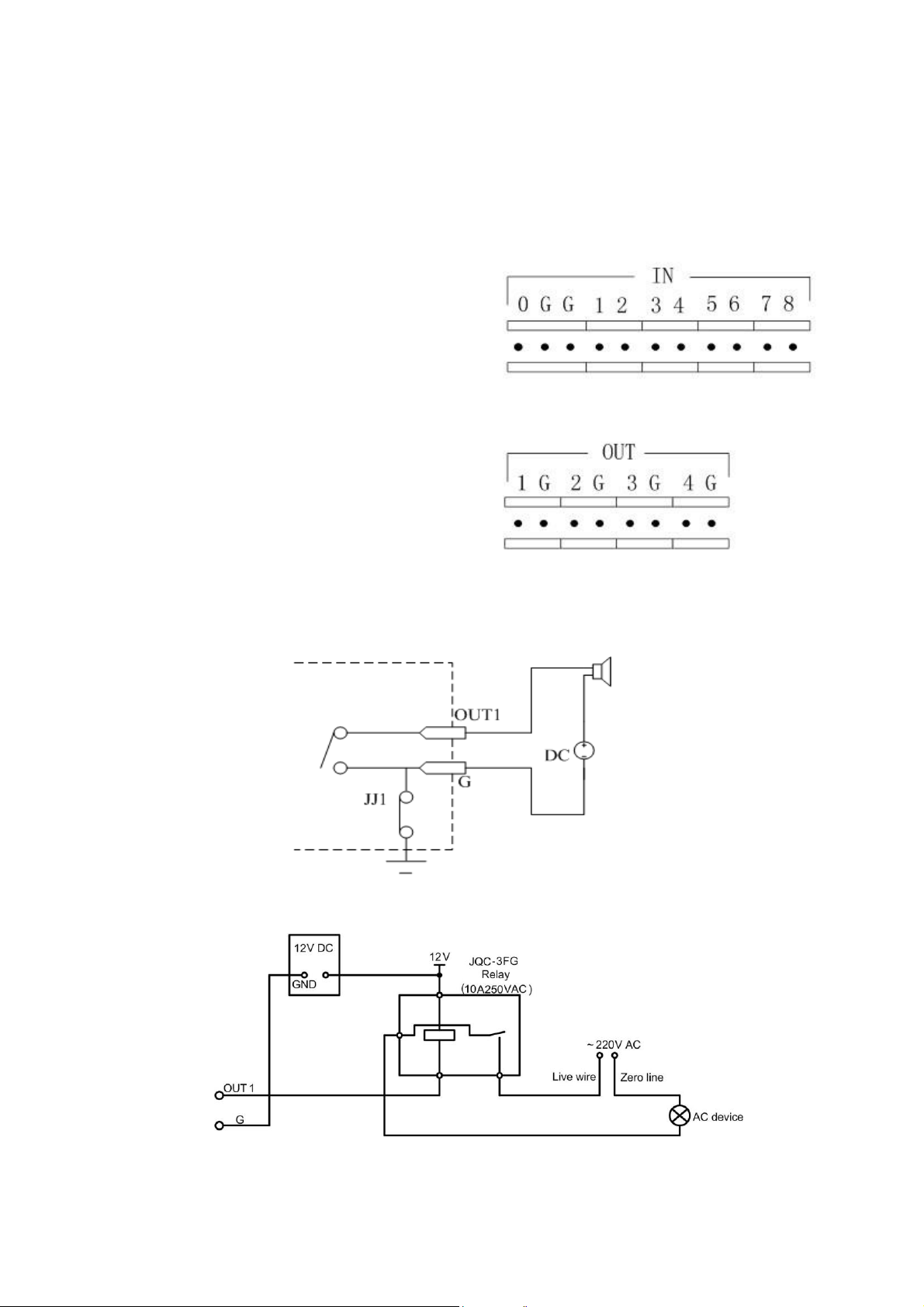
2.4 External Alarm In/Out Connection
Alarm input port (dry node):
G (GND): Connect the GND of
sensor.
1~8: Alarm input, support normal
open/normal close.
0: Reserved.
Alarm output:
1G~4G: 4 relay output.
Alarm input dry node
Alarm output connection
Connect with DC device
Connect with AC device

17
2.5 Powering up
1. Switch on all connected equipment.
2. Connect the power cable to the unit
3. Switch on the power
18
Chapter3 Operational Instructions
1 2 3 4 5 6 7 8 9 10 11 12 13 14 15 16
PW
R
ENTE
R
9090
Tx/Rx
LINK
HDD
MOD
EM
ALAR
M
STATU
S
REA
DY
90
90
90
90
HIKVISION
1 2 3
4 5 6
7 8 9
0 F1 F2
ABC DEF
GHI JKL MNO
PQRS TUV WXYZ
EDIT PTZ
MENU ESC A PREV
PLAY
REC INFO VOIP
WIPE
R
AUT
O
IRIS
FOCU
S
ZOO
M
SHO
T
+
+
+
-
-
-
2
4 5
6
7
3
8
PUSH
1
2
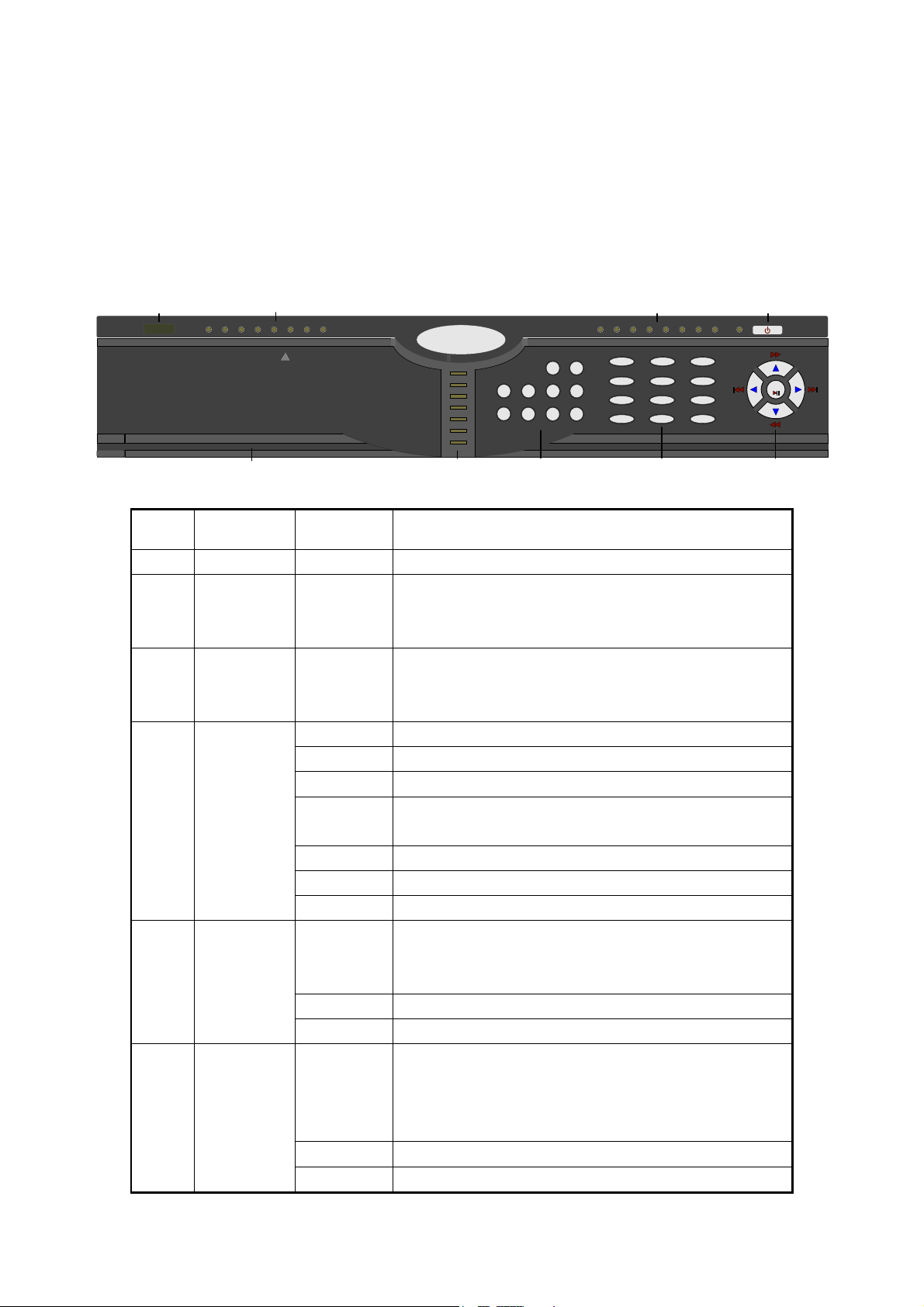
Index
Type
Name
Description
1
IR receiver
2
State
Lamps
1 - 16
Show 1-16 camera status. Green means recording;
Red means network transmission; Orange means
recording and network transmission.
3
POWER
POWER
Device switch with power indicator lamp. Green
means DVR is working; Red means DVR is powered
off; No light means no power is supplied.
4
State
Lamps
READY
DVR is ready
STATUS
Green means you can use IR remote control
ALARM
Red means there is alarm
Modem
Green means modem connection and dial-up
successful
HDD
Twinkle in red means reading or writing HDD
LINK
Green means network is OK
Tx/Rx
Twinkle in green means data is being transmitted
5
Input Keys
Numeric
Keys
Input number, lower case, upper case character and
symbols
F1
[LIGHT] in PTZ control
F2
[AUX] in PTZ control
Function
Keys
MENU
1. Switch preview mode into menu
2. Brush control short key [WIPER]
3. Press [MENU] for more than 5 seconds to cancel
button beep sound
ESC
Cancel and back to parent menu
PLAY
1. Local playback
3.1 DVR Front Panel

19
6
2. [AUTO] in PTZ control
REC
1. Manual record
2. [SHOT] in PTZ control (call PTZ preset)
EDIT
1. In edit state, delete the current cursor character
2. [IRIS+] in PTZ control
3. Select or × to enable or disable
PTZ
1. Enter into PTZ control mode
2. [IRIS-] in PTZ control
A
1. Input switch (number, lower case, upper case
and symbol)
2. [FOCUS+] in PTZ control
3. In preview mode, display or hide the channel
status bar
PREV
1. Multi screen preview switch
2. Switch menu mode into live view
3. [FOCUS-] in PTZ mode
INFO
[ZOOM+] in PTZ control
Main/Aux
1. Switch main/aux video output control mode (This
function is not available for DS-8704HI-S DVR)
2. [ZOOM-] in PTZ control
7
Control
Keys
Direction
Keys
Composed of [] , [], [] and []
1. Menu mode, use direction keys to select, press
[Enter] or [Edit] key for edit
2. PTZ direction control
3. Playback speed control
ENTER
1. Menu confirmation;
2. Select or × to enable or disable;
3. Pause playback.
20
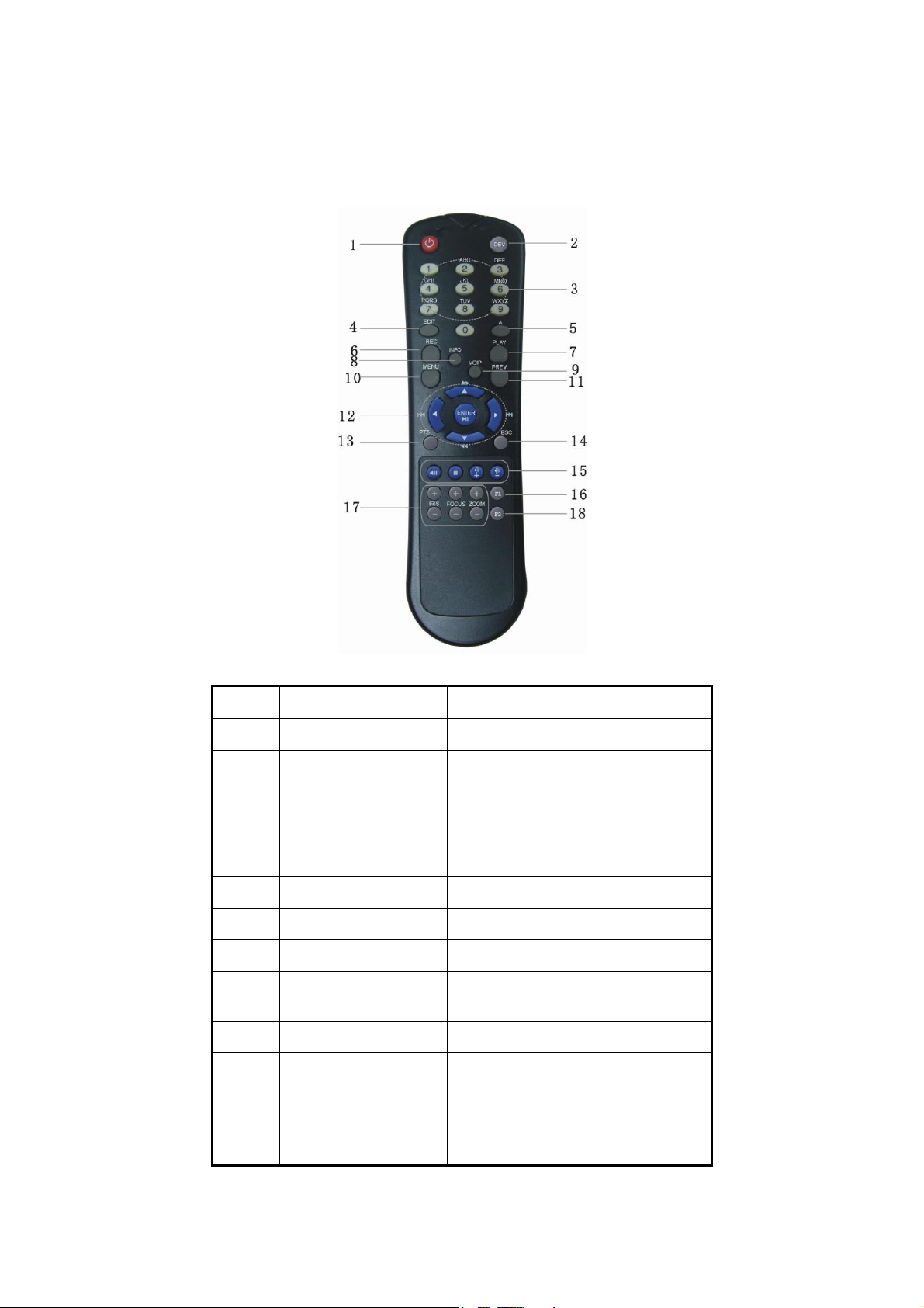
3.2 IR Control
Index
Name
Description
1
POWER
Turn off device
2
DEV
Enable/Disable IR remote control
3
Numeric Keys
Same as numeric keys of front panel
4
EDIT
Same as [EDIT] key of front panel
5
A
Same as [A] key of front panel
6
REC
Same as [REC] key of front panel
7
PLAY
Same as [PLAY] key of front panel
8
INFO
Same as [INFO] key of front panel
9
VOIP
Same as [Main/Aux] key of front
panel.
10
MENU
Same as [MENU] key of front panel.
11
PREV
Same as [PREV] key of front panel.
12
Direction Keys
ENTER
Same as direction keys and enter key
of front panel
13
PTZ
Same [PTZ] key of front panel

21
14
ESC
Same as [ESC] key of front panel
15
Reserved
Reserved for future usage
16
F1
Same as [F1] key of front panel
17
Lens control
IRIS, FOCUS ZOOM for lens control
18
F2
Same as [F2] key of front panel
Loading the batteries into the IR controller
1. Remove the battery cover.
2. Insert the battery. Please take care that the poles (+ and -) are correctly
positioned.
3. Replace the battery cover.
Start to use IR controller
Press [DEV] key, input the DVR device ID (default is “88”, can be changed in
“Display” menu) and then press [ENTER] key. If the “STATUS” lamp of DVR front
panel is turned into green, it means you can use IR controller to operate this DVR.
Stop using IR controller
When IR controller status is on, press [DEV] key again, the “STATUS” lamp will
be turned off. The IR controller can not control this DVR.
Switch the DVR off
When IR controller status is on, press [POWER] key for several seconds, the
DVR will be powered off.
When IR controller can not work normally
Check batteries poles.
Check the remaining charge in the batteries.
Check IR controller sensor is mask.
Please change another IR controller to try again. If the problem is still existed,
please contact administrator.

22
3.3 OSD Menu Description
Menu Name
Function
Menu Name
Function
Display
Device ID
Require Password
Video standard
Brightness
Menu transparency
Screen saver
VGA resolution
DST
Date and Time
Preview
Camera
Camera name and position
Color
OSD Display mode, position
and OSD style setup
Mask area setup
View tampering area and
response setup
Video signal loss
Motion detection sensitivity,
area and response setup
Recording
Overwrite/Stop recording
Recording parameters setup
Record schedule
PreRecord time
PostRecord time
Network
DVR IP address
DNS IP
Multicast IP address
Remote host IP and port
PPPoE setup
Alarms
Alarm input type (Normal
open/ Normal close)
Alarm response and PTZ
linkage
Alarm output and schedule
Exception setup
PTZ
PTZ parameters
Preset setup
Sequence setup
Tour setup
User
Add or delete user
Password setup
User rights setup
Utilities
RS232 setup
Restore factory parameters
Multi-Playback
Upgrade firmware
HDD management
Stop alarm output
Reboot
Power off
View log
System information
Tools
3.3.1 Main Menu Items
23
3.3.2 Menu Operation
How to enter into menu mode
Press [MENU] key to enter into DVR main menu
Press [PLAY] key to enter into playback menu
Press [REC] key to enter into manual record menu
Press [PTZ] key to enter into PTZ control interface
Notes: You must input user name and password. The default user name is “admin”
and password is “12345”.
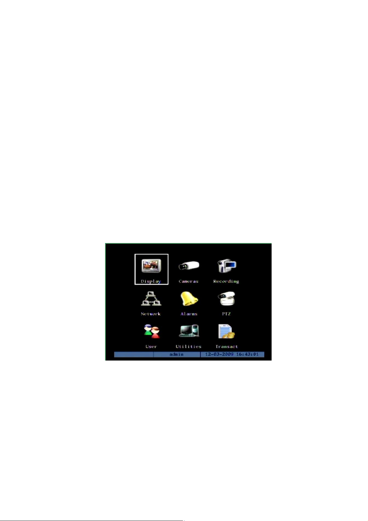
Main Menu Description
The main menu interface is following:
There is one small rectangle frame named “Active Frame”. It can be moved from one
item to another by using direction keys ([↑] [↓] [] []). When the “Active Frame” is
located on one item and highlight it, you can press [ENTER] key to enter into the sub
menu. For example, move the “Active Frame” to “Camera” item, press [ENTER] to enter
into the secondary menu as following:
24
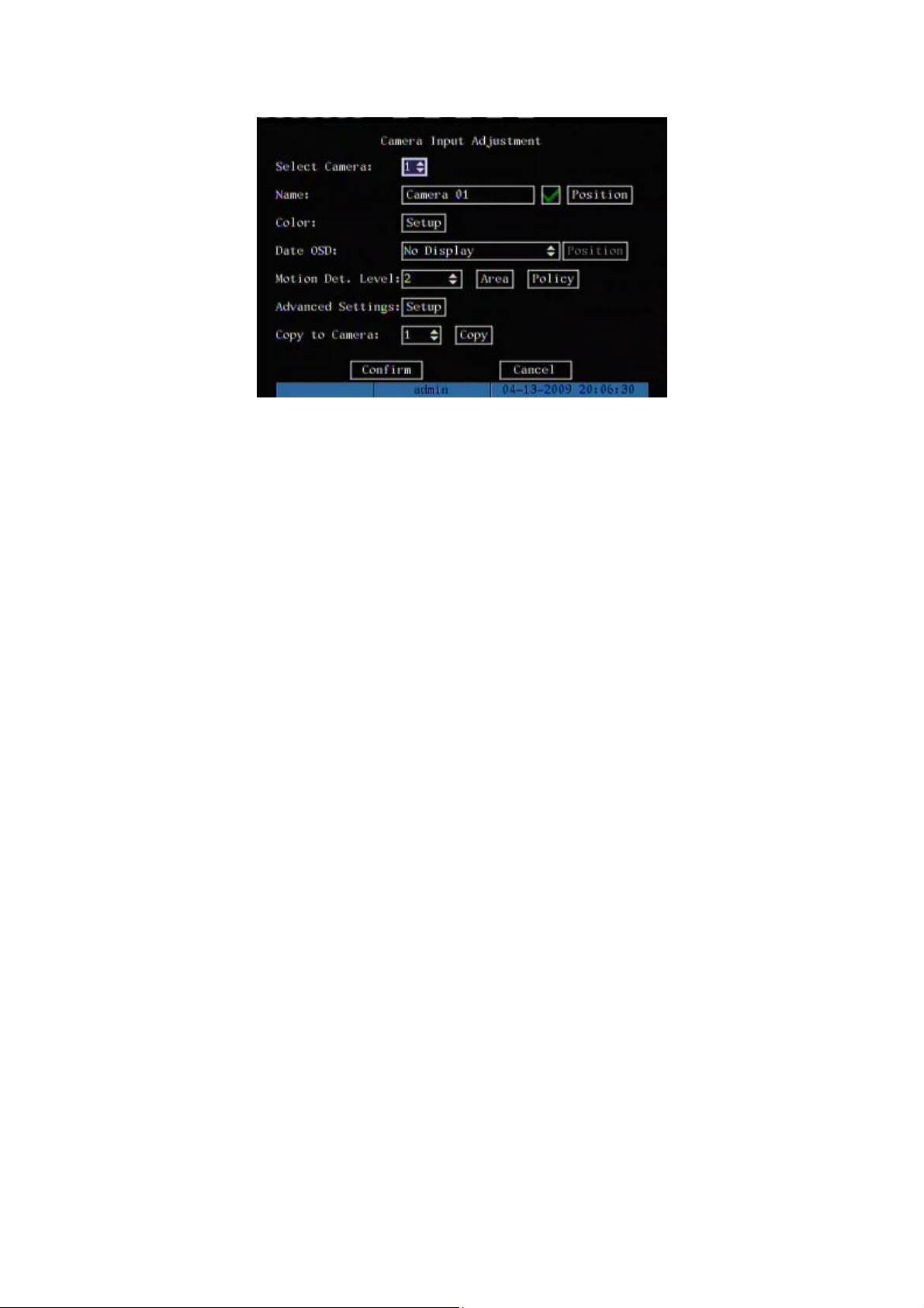
Each menu contains different kinds of items. There is a small rectangular frame
named “Active Frame” which is pointing to the selected item. This “Active Frame” can be
moved by direction keys ([↑] [↓] [] []). There are such kinds of menu items:
a) Check Box: Provide 2 options, “” means enable and “×” means disable. You
can use [ENTER] or [EDIT] key to switch over.
b) List Box: Provide more than 2 options. However, only one of them can be
selected. You can press [ENTER] or [EDIT] to enter into edit mode, then use [↑]
and [↓] to select one option. For example, on the right side of “Select Camera”,
there is a list box for you to select one camera.
c) Edit Box: This is for you to input characters. Press [EDIT]key to enter into edit
status, you can input characters as following:
Press [A] key to select number, upper case, lower case or symbols;
Use [] and [] keys to move cursor;
Use [EDIT] key to delete the character in front of cursor;
Press [ENTER] or [ESC] to exit edit.
d) Button: Execute a special function or enter into next sub-menu. For example,
press “Policy” button to enter into sub-menu. Press [Confirm] to save
parameters and return to parent menu. Press [Cancel] button to cancel and
return to parent menu. The button in grey means it can be operated only after it
is enabled.

25
How to exit menu
Press [PREV] or [ESC] key to exit menu and return to preview mode.

26
3.4 Character Input
In the menu interface, if you enter into edit status, for example, in the “camera name”
edit box at the bottom of screen, the input status is appeared:
Here it means you can press numeric keys to input digital number.
Press [A] key to change input methods. You can select “number”, “Uppercase”,
“Lowercase” or “Symbol”.
Uppercase
Lowercase
Symbol
There are 24 symbols in all. They are divided into 4 pages, and you can press [0] key to
turn to next page.

27
Chapter4 Basic Operation Guide
4.1 Power on
Note: Please make sure the power supply matches DVR and AC cable
connected correctly. Before switch DVR on, please connect one monitor with VOUT
or VGA interface. Otherwise, you can not see graphic user interface and can not
operate.
If [POWER] lamp is off, please do as following:
Step1: Connect AC cable correctly;
Step2: Switch on the power button on the real panel.
If [POWER] lamp is in red, just press [POWER] button to start DVR.
When DVR is started, [POWER] lamp is in green. On the monitor or VGA display,
DSP and HDD initialization process will be shown.
The first line represents DSP initialization. If the DSP icon is “×”, it means that the
DSP is initialized error, please contact administrator at once.
The second line represents HDD initialization. Icons of each SATA HDD are displayed.
If the HDD icon is “×”, it means the corresponding HDD is not installed or not detected. If
HDD is not detected, please contact administrator.
Note: If HDD is not installed or not detected, there is “No Disk” text string in
DVR preview screen.
28
4.2 Live View
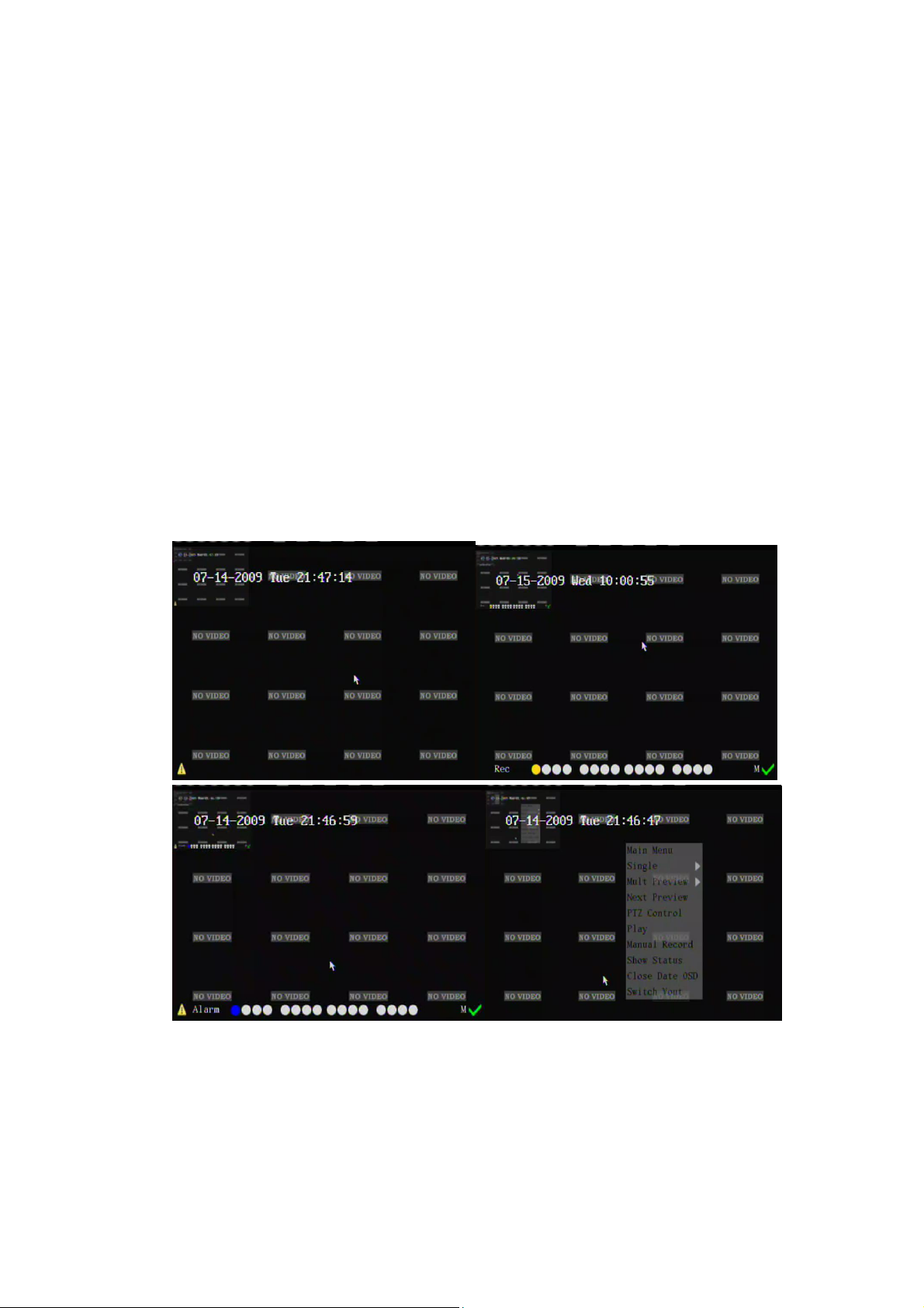
DVR will enter into live view mode after it is started.
On preview screen, you can see date, time, camera’s name and camera status icon.
Set system date and time in “Display” menu, referring to 5.4; Change camera name in
“Camera” menu, referring to 5.5.
In the screen, it will display alarm icon, record and alarm status of each camera.
Record and alarm status will switch over automatically. Alarm icon only appears when
alarm happens.
Press button [A] to switch 【Display all status indicator ->Close all status indicator
->Display alarm info->Display camera status indicator】
Mouse operation:
Right click the mouse can change the status.【Show Alarm Status-> Show Chan
Status-> Show Status-> Close status】
29
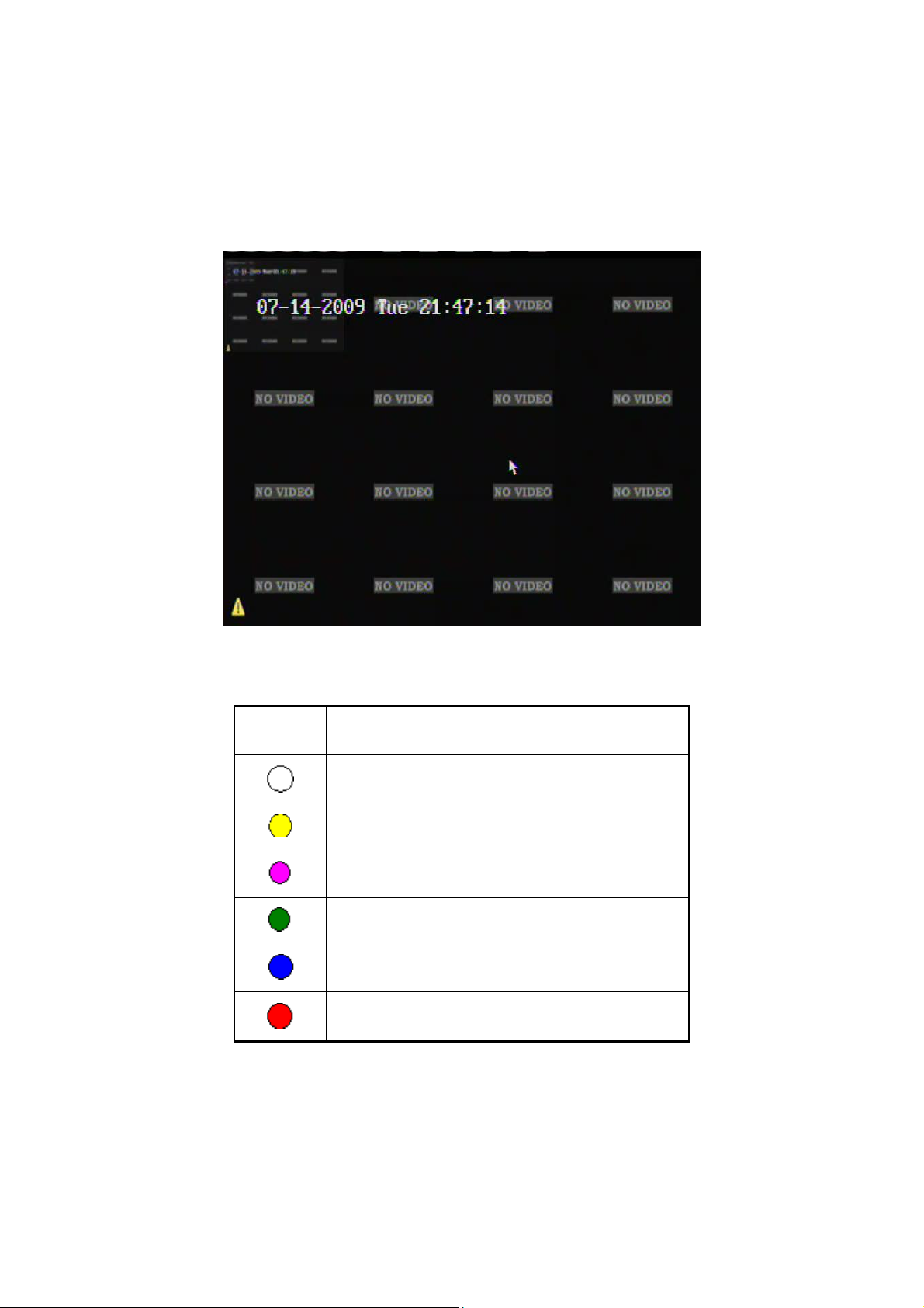
Large font OSD display: In multi-screen mode, press ESC button to display/hide
Icon
Icon Color
Status Description
White
No video signal
Yellow
Video input
Pink
Manual recording
Green
Continuous recording
Blue
Motion detect recording
Red
External alarm recording
large font OSD. Right click mouse by selecting the 【Show Date OSD/Close Date OSD】
to display/hide the large font OSD.
Also these functions support in Aux video out.
Camera record status is following:
Note: When alarm happens, no matter it displays alarm icon or not, press [zoom +] key
can enter “alarm/exception information” interface. If it needs password, it will pop-up the
login interface. Mouse control is only effective on alarm icon displayed!
30
Icon
Icon Color
Status Description
White
Video signal lost
Yellow
View tampering alarm
Pink
Motion & External alarm
Green
No alarm
Blue
Motion alarm
Red
External alarm
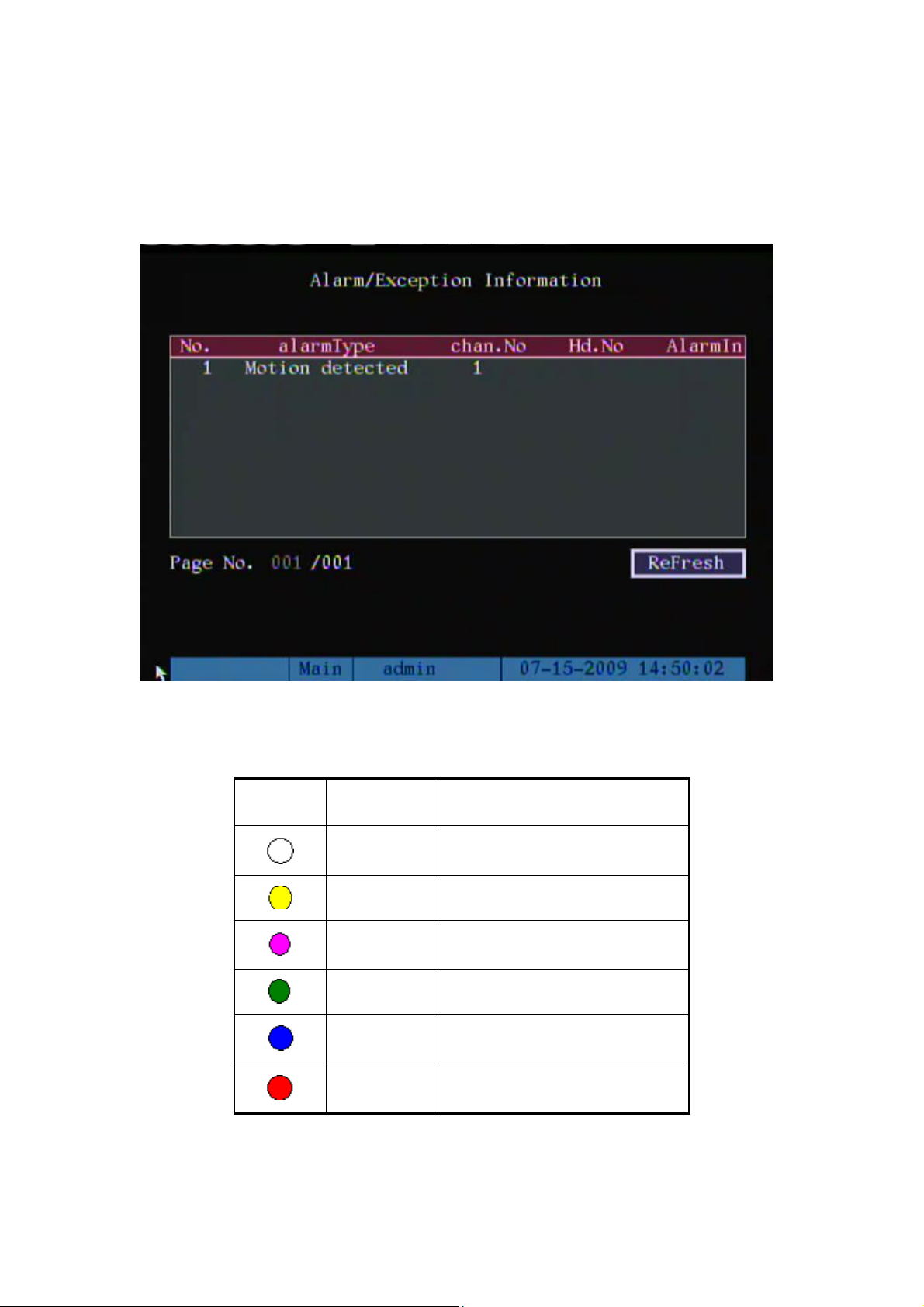
Alarm/Exception information interface
Alarm/Exception information interface contains: list box, page and refresh OCX.
Refresh button used for refresh present alarm information.
Camera alarm status is following:
Press numeric keys to switch over individual camera live view. If DVR has less than

31
10 channels, press one numeric key to switch corresponding channel. For example, press
[2] key to preview 2nd camera. If DVR has 10 or more than 10 channels, press two
numeric keys to switch to corresponding channel. For example, press [0] [2] to preview
2nd camera; and press [1] [2] keys to preview 12th camera.
Press [EDIT] key to manual sequence preview. You can set the auto preview mode in
“Preview” menu, referring to 5.10.
Press [PREV] key to switch multi-screen preview.
Press [Enter] key to pause live preview.

32
4.3 Login
Note: When DVR is delivered from factory, there is only one default
administrator named “admin”, and password is “12345”. The administrator’s name
can not be modified, while the password can be modified. The administrator can
create 15 users and define their user rights.
Login dialog is following:
Use [] / [] keys to select one user, press [] key to enter into “Password” edit box,
input corresponding password, press [ENTER] key to exit edit box. The “Active Frame”
will be moved to “Confirm” button. Press [ENTER] key to enter into main menu. If there is
beeper alarm, it means the user name and password are not matched. After three error
times, DVR will enter into live view mode.

33
4.4 PTZ Control
Note: The user must have the “PTZ control” right. Please refer to “PTZ Setup”
in chapter 5.14.
PTZ control interface
In preview mode, press [PTZ] key, in the login dialog, select one user name and input
the correct password, you can enter into PTZ control interface.
In menu mode, press [PTZ] key, you can enter into PTZ control interface directly.
There is “PTZ Control” prompt in the PTZ control interface. The displayed camera
name means which channel’s PTZ is under control. For example, “Camera 01” means you
are controlling the 1st camera PTZ.
Select channel
In PTZ control mode, you can press numeric keys to select channel. If DVR has less
than 10 channels, press one numeric key to select. For example, press [2] key to select
2nd camera PTZ. If DVR has 10 or more than 10 channels, you must press two
numeric keys to select. For example, press [0] [2] to select 2nd camera PTZ, and
press [1] [2] to select 12th camera PTZ.

34
After you select the camera PTZ, you can use the short keys to control PTZ.
PTZ control keys description
Direction control keys: [↑], [↓], [←], [→]
ZOOM control keys: [ZOOM+], [ZOOM-]
FOCUS control keys: [FOCUS+], [FOCUS-]
IRIS control keys: [IRIS+], [IRIS-]
Adjust preset keys: [REC/SHOT];
Auto control key: [PLAY/AUTO]
Wiper control key: [WIPER/MENU]
Light control key: [LIGHT/F1]
Auxiliary control key: [AUX/F2]
Call preset description
In PTZ control mode, press [REC/SHOT] key, and press the preset number (three
numeric keys), DVR will call the corresponding preset number. Repeat pressing
[REC/SHOT] key, and press the preset number, DVR will call that preset number.
When you exit PTZ control mode, the camera will stay at the current position.
Note: The PTZ preset number is set already. Please refer to PTZ menu for preset setup.
Start/Stop auto in PTZ control mode
In PTZ control mode, press [PLAY/AUTO] key to start PTZ auto function. Press
[PLAY/AUTO] key again to stop.
When PTZ is in auto mode, if you exit PTZ control mode, PTZ will continue auto
function. You must enter into PTZ control mode again, and press [PLAY/AUTO] key to
stop.
Exit PTZ control mode
Press [ESC] or [ENTER] to exit and return live view mode.
35
4.5 Manual Record
Note: The user must have the corresponding right, DVR has HDD and HDD is
formatted already.
Manual record
In live view mode, press [REC] key, in the pop-up login dialog, select the name and
input the correct password, you can enter into the “Manual Record” interface.
In menu mode, press [REC] key to enter into “Manual Record” interface directly.
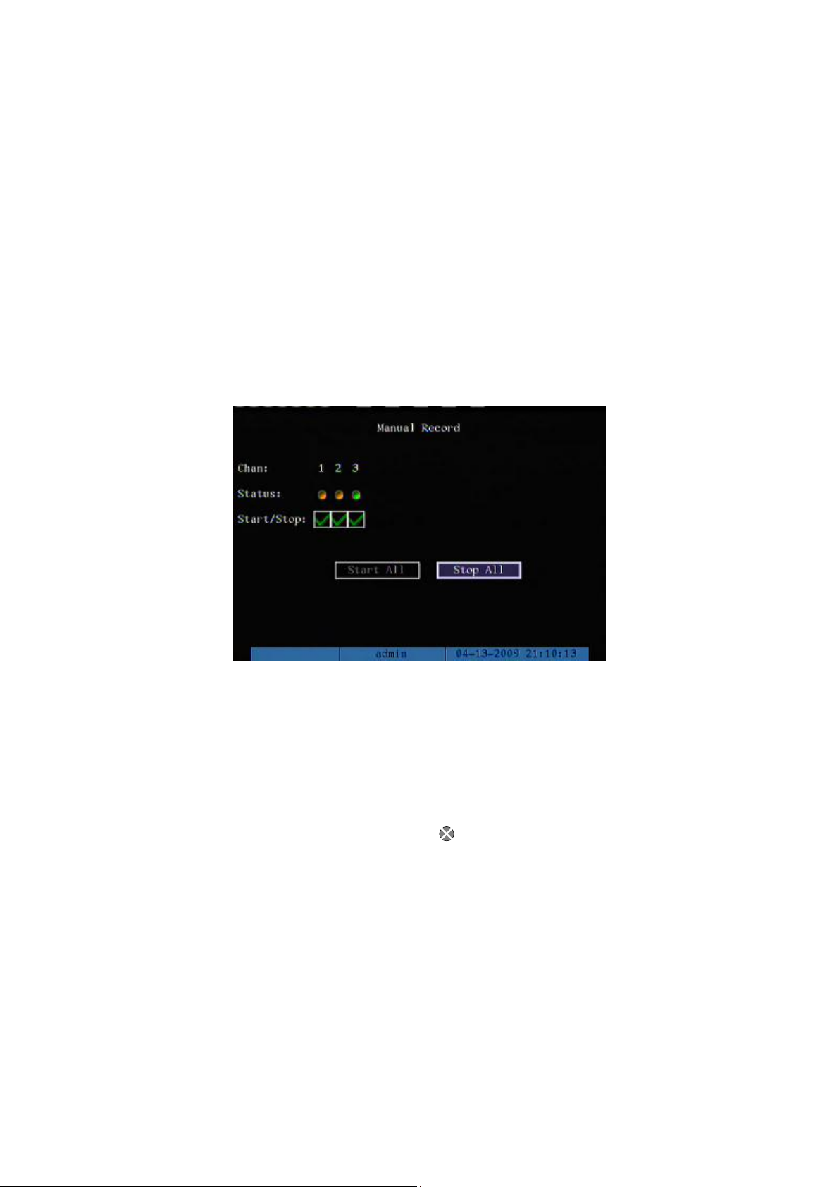
Description
Manual record interface has following parts: channel number, channel status,
start/stop record, start all and stop all buttons.
Channel: List the channel number that DVR has.
Status: Channel work status has 4 cases: means idle. Green means the channel
is recording (including continuous recording, alarm recording, motion detection recording).
Red means network transmission. Orange means both recording and network
transmission.
Start/Stop: “” means enable corresponding channel recording. “Blank” means stop
recording.
Start All: Press this button to start all channels recording.
Stop All: Press this button to stop all channel recording.

36
Exit manual record
Press [ESC] key to enter into preview mode. Press [MENU] key to enter into main
menu. Press [PLAY] key to enter into playback menu. Press [PTZ] key to enter into PTZ
control mode.

37
4.6 Playback
Note: The user must have “Playback” right.
Playback interface
In live view mode, press [PLAY] key, in the pop-up login dialog, select username and
input correct password, you can enter into “Playback” interface.
In menu mode, press [PLAY] key, you can enter into “Playback” interface directly. The
Play back interface is different when you enable or disable the multi-playback function.
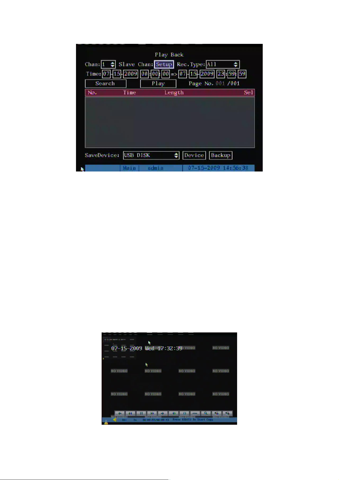
Multi-playback Enabled Multi-playback Disabled
Multi-playback Enabled
If DVR enable the multi-playback function, you can maximum select 16-channels.
Main Channel: Use [↑] or [↓] key to select one channel.
Slave Chan: If DVR enable multi-channel playback, you can select [Setup] to
enable/disable relevant channels. These enabled channels can be playback

38
synchronously. If no Slave channel is selected, only the main channel is playback.
Rec Type: Use [↑] or [↓] to select recorded files type. The file type options have “All”,
“All Time”, “Motion Detect”, “Alarm” and “Manual”.
Time Section: You can define the search time section. Move “Active Frame” to the
time edit box, use numeric keys to input the detail time.
Search: Search the matched recorded files and display them in the list box. If there is
not matched file, a corresponding dialog box will be pop-up.
Play by Time: Playback the recorded stream directly based on the time section.
Select Page: In the file list box, each page will only display 8 files. If the matched files
are more than 8, you can select page to list other files. 500 pages (4000 files) can be
searched in one time. You can use numeric keys or [↑] [↓] keys to select page.
File List Box: List the matched files. File started time, file size are displayed in the list
box. You can use [↑] [↓] keys to move the scroll bar to select file.
SaveDevices: You can select USB flash, USB HDD, USB CD/DVD or SATA CD/DVD
to backup the files or clips.
Device: You can select USB device through this menu, and you can create or delete
folders under root directory. In this menu, the HDD free space also will be displayed.

39
Multi-playback Disabled
Description
If DVR only supports one channel playback, you can not select second channel. If
DVR can support two channels playback, you can select second channel.
Main Channel: Use [↑] or [↓] key to select one channel.
Second: If DVR support 2-ch playback, you can use [↑] or [↓] key to select the
second channel except the main channel. These two channels can be playback
synchronously. If you select the second channel as none, only the main channel is
playback.
Rec Type: Use [↑] or [↓] to select recorded files type. The file type options have “All”,
“All Time”, “Motion Detect”, “Alarm” and “Manual”.
Time Section: You can define the search time section. Move “Active Frame” to the
time edit box, use numeric keys to input the detail time.
Search: Search the matched recorded files and display them in the list box. If there is
not matched file, a corresponding dialog box will be pop-up.
Play by Time: Playback the recorded stream directly based on the time section.
Select Page: In the file list box, each page will only display 8 files. If the matched files
are more than 8, you can select page to list other files. 500 pages (4000 files) can be
searched in one time. You can use numeric keys or [↑] [↓] keys to select page.
File List Box: List the matched files. File started time, file size are displayed in the list
box. You can use [↑] [↓] keys to move the scroll bar to select file.
SaveDevices: You can select USB flash, USB HDD, USB CD/DVD or SATA CD/DVD
to backup the files or clips.
Device: You can select USB device through this menu, and you can create or delete
folders under root directory. In this menu, the HDD free space also will be displayed.

40
USB backup file local playback:
The files which saved in the USB device could be playback locally and the suffix
name of file should be “.mp4”.
Backup: You can select all channels files and Backup all recorded files.
Two kinds of playback mode
1. Search and playback file: In the playback interface, you can select main channel,
Slave Chan (Multi-ch playback), record type, time section. Move “Active Frame” to
“Search” button and press [ENTER] key, DVR will search and list the matched files.
41
One channel search
If the matched files are more than 8, you can use “Page No.” to select page (use
numeric keys or [↑] [↓] keys to select page). In the file list box, use [↑] [↓] keys to move the
scroll bar to the file, press [ENTER] key to playback the file. If the second channel is
selected, these two channels can be playback synchronously.
If DVR can not find the matched files, a message dialog will be pop-up.
2. Playback by Time: In the playback interface, select main channel, slave channel
(Multi-channel playback), record type and time section, move “Active Frame” to “Play”
button, press [ENTER] key, DVR will start to playback based on time section.
Operation when playback
Playback when multi-playback disabled:
Single-Channel Playback

42
: Backward 30 seconds.
: Decrease the play speed.
: Play/Pause the video.
: Increase the play speed.
: Forward 30 seconds.
: Disable the volume.
: Start/Stop to record the video for backup.
: Display/Hide the control bar
: It will prompt a blue area, you can drag this area by mouse and double click it to
enlarge it to full screen.
Playback when multi-playback enabled:
Multi Channels Playback
: Switch to previous group channels video.
: Switch to next group channels video.
: Switch to 2/4/9/16-screens playback.

43
At the bottom of image, there is an information bar and the following information is
included: Volume, Play Progress, Play Speed, Played Time and File Total Time.
Display/Hide information bar: [MENU]
Open/Close sound: [PLAY]
Adjust play progress: [←] (Backward), [→] (Forward). The unit is “%”.
Adjust play speed: Normal speed is “1x”. Use [↑] to increase play speed (2X,
4X, 8X and MAX). Use [↓] to decrease play speed (1/2X, 1/4X, 1/8X and
Frame by Frame)
Pause/Continue: Press [ENTER] to pause/continue playback. If played
frame by frame, Press [ENTER] to play one frame.
Copy segment: [EDIT]
Exit: [ESC]
Playback switch: When in multi-channel playback, press [PREV] to switch
between main channel and the other channels.
Note: When DVR is busy, if you select high play speed, maybe there is difference for
actual play speed.
Exit playback
In playback interface, press [ESC] key to enter into preview mode.
In playback interface, press [MENU] key to enter into main menu, press [REC] key to
enter into manual record, and press [PTZ] key to enter into PTZ control mode.

44
4.7 Backup Recorded Files
Note: The user must have “Playback” right. Please connect with backup
devices before you start to backup.
In the playback interface, you can backup the recorded files.
In the preview mode, press [PLAY] key, in the login dialog, select username and input
the correct password, you can enter into the playback interface.
In the menu mode, just press [PLAY] key, you can enter into playback interface
directly.
Backup intraday recorded files
In the playback interface, move “Active Frame” to “Backup” button, press [ENTER]
key, all intraday recorded files of any or all channels can be backup to the save device. A
pop-up dialog will display the backup status.
If backup device is not connected correctly or DVR do not detect the backup device,
“Device Error” message dialog will be pop-up. Please ask administrator for more
information.
Backup the files that matched your requirement
Step 1: Search the matched files
In the playback interface, select one channel and record type, input the time section,
move “Active Frame” to “Search” button, press [ENTER] key, DVR will start to find and list
the matched files.
Step 2: Select the files that you want to backup
In the file list box, use [↑] or [↓] keys to move the scroll bar. When the scroll bar stays
at the file you wan to backup, press [EDIT] key to select it. The symbol “” is the selection
tag. You can use the same method to select other files you want to backup. After finish,
you can do next step.
Step 3: Select backup device
Please confirm the backup device: USB flash memory, USB HDD, USB CD/DVD,
45
SATA CD/DVD or SATA HDD, and select the corresponding backup device.
Step 4: Start and finish backup
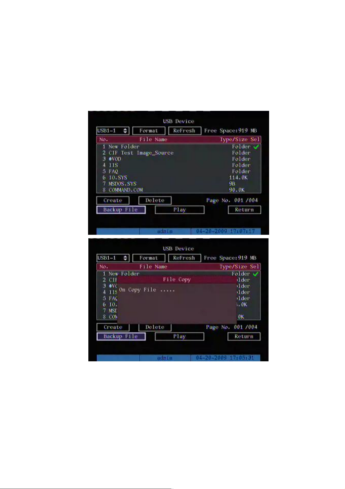
Move “Active Frame” to “device” button and press [ENTER] key to enter into USB
device menu.
Select a backup folder, and click Backup File button to copy files.

46
Backup File
Backup video clips
You also can backup the video clips when the file is being playback. The steps are:
1) Enter into the interface of playback the files or playback by time;
2) Press [EDIT] key to start selecting the current playback image, and press [EDIT]
again to stop selecting. This segment is selected;
3) You can repeat step 2 to select many segments. 30 segments can be selected in
all;
4) After you select all segments, press [ESC] key, a message window will pop-up. If
you press “Confirm” button, DVR will start to backup the selected segments. If

47
you press “Cancel” button, DVR will abort backup.
Backup Video Clips
Note: The backup function is effective when two channels are playback
synchronously. In such case, each channel can backup 30 segments so 60 segments can
be backup for two channels.
Playback backup video files
You can use our file player software to playback the video files in PC. You can find the
player software in attached CD.
Exit playback interface
Please refer to chapter 4.6.

48
4.8 Turn off DVR
Note: Do not switch off the power directly in case of damaging HDD. The
correct step is using “Power Off” in the “Utilities” menu, or [POWER] key on the
front panel or on IR controller.
Shut down DVR normally
Use menu
Enter into “Utilities” menu, move “Active Frame” to “Power Off” button and enter into
power off dialog, press “Confirm” to shut down the DVR.
Use [POWER] key of front panel or IR controller
Press [POWER] key for above 3 seconds.
In preview mode, a login dialog will pop-up, select user name and input password,
press [Enter] to enter into power off dialog and press “Confirm” to shut down DVR. If you
input error password for three times, DVR will return preview mode.

49
In menu mode, if the user has “Utilities” right, you can enter into power off dialog,
press “Confirm” to shut down DVR. Otherwise, the user can not shut down DVR.
If DVR is shut down correctly, the [POWER] lamp is in red.
Shut down DVR abnormally
Use the power switch of real panel
When DVR is run, if you switch off the power, the HDD in DVR will be damaged.
Please avoid such operation.
Take away the power cable
Please avoid taking away the power cable directly.
Note: In some cases, when the power supply is abnormal, DVR will be damaged. We
suggest you to use those stable power supplies.

50
Chapter5 Advanced Operation Guide
Only the users that have “Parameters Setup” right need to read this chapter. When
the following parameters are modified and saved, you must reboot the DVR to make the
new parameters take into effective. Other parameters do not need to reboot.
Any network parameters in “Network” menu
Stream type, resolution and record schedule in “Recording” menu
External alarm sensor type in “Alarms” menu
View tampering alarm schedule in “Camera” menu
Video lost alarm schedule in “Camera” menu
Motion detection alarm schedule in “Camera” menu
External alarm schedule in “Alarms” menu
Alarm output schedule in “Alarms” menu
RS232 work mode in “RS232” menu
Change video output standard in “Display” menu
Change PTZ parameters in “PTZ” menu

51
5.1 User Management
When DVR is left from factory, there is one default administrator. The name is “admin”
and password is “12345”. The name can not be changed, while the password can be.
Move “Active Frame” to “User” item, press [ENTER] key to enter into “User
Management” menu.
52
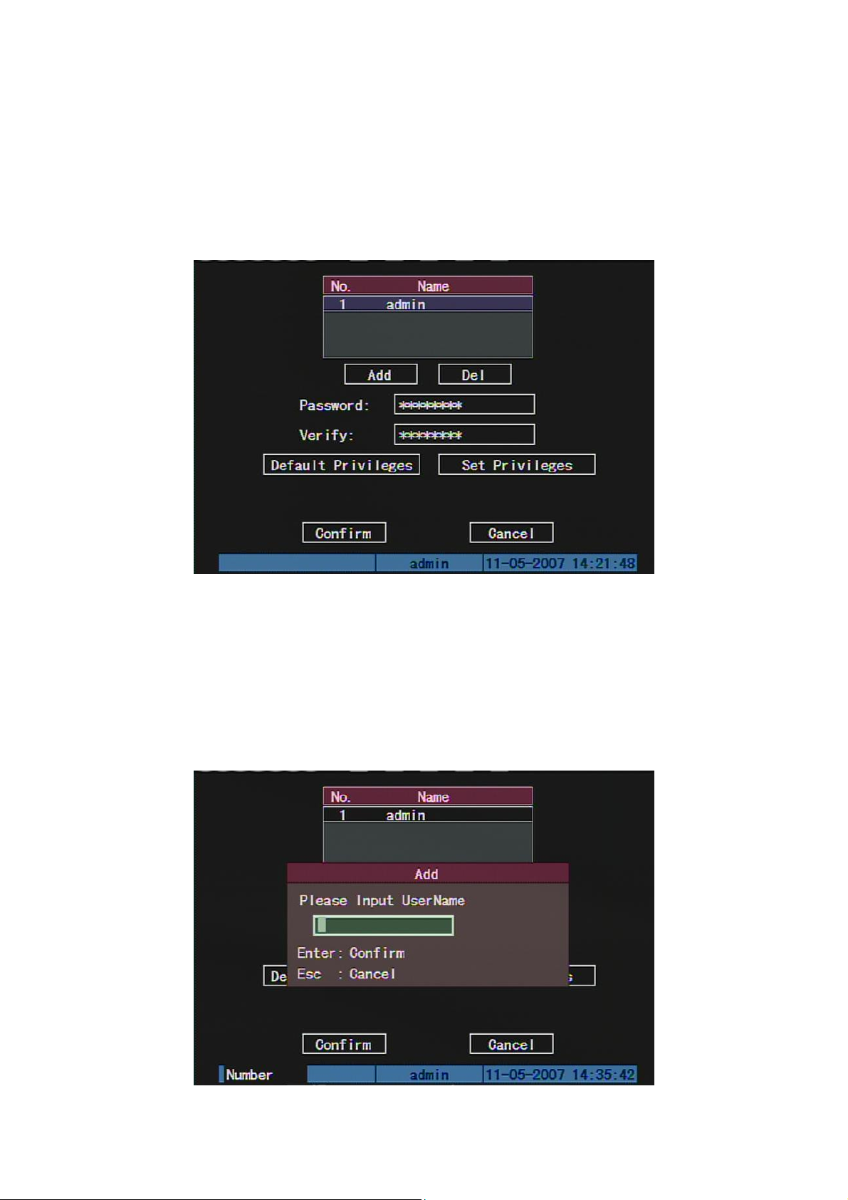
5.1.1 Add User
The steps are following:
Step 1: Enter into “User Management” menu
Step 2: Add new user name
In the “User Management” menu, move “Active Frame” to “Add” button and press
[ENTER], in the pop-up dialog, input the new user name, press [ENTER] and return “User
Management” menu. 15 users can be added in all.

53
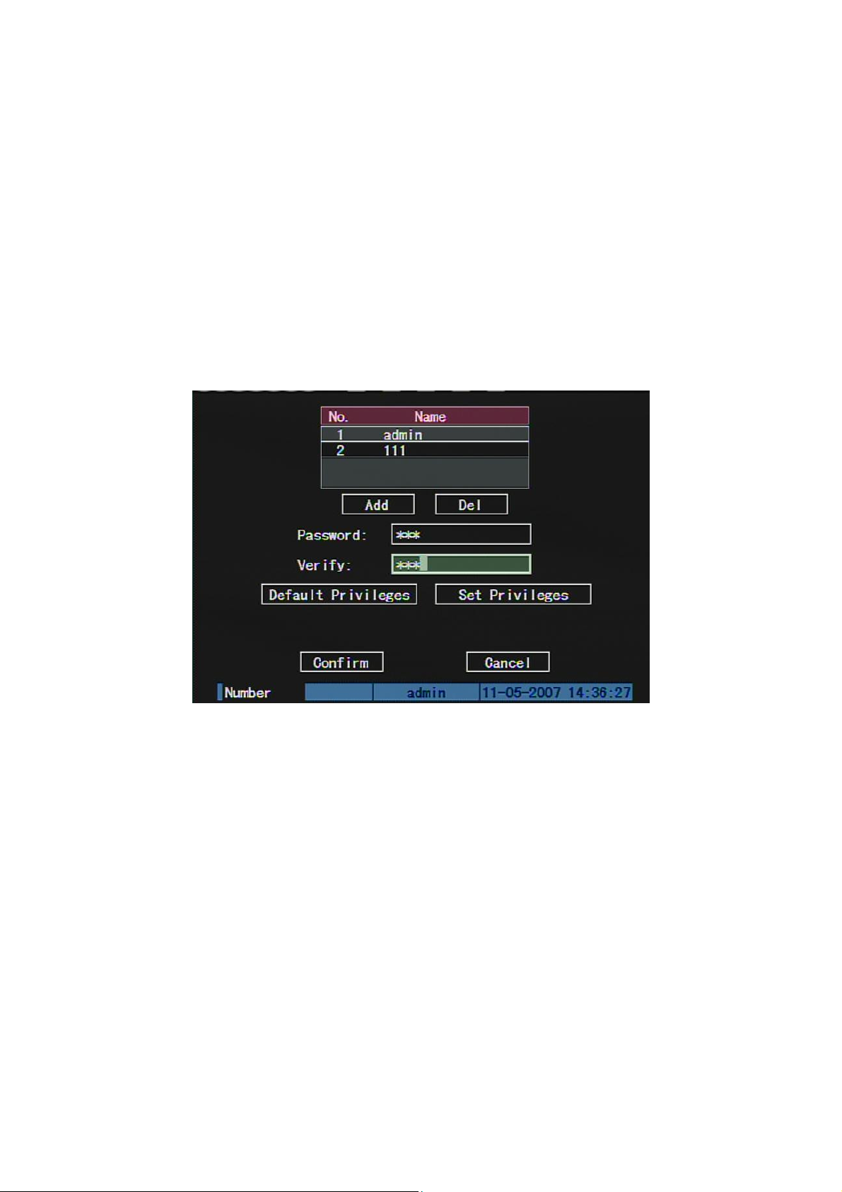
Step 3: Setup the password for new user
After you add one new user, the password is null. You can skip this step if you do not
want to change the password.

54
5.1.2 Delete User
In “User Management” interface, you can use [] [] keys to select one user, then
use [], move “Active Frame” to “Del” button, press [ENTER], in the pop-up confirmation
dialog, press “Confirm” button to delete the selected user and return. Press “Cancel” or
[ESC] to abort deleting.
55
5.1.3 Password Modification
Press [MENU] key, in the login dialog, select the username as “admin”, use [→] key,
move cursor to password edit box, input “12345”, press “Confirm” to enter into
administrator menu.
Move “Active Frame” to “User” icon, press [ENTER] key to enter into “User
Management” menu.
In the user name list box, all users are listed. You can use [][] keys to select one
user, and use [→] key to move “Active Frame” to password edit box, and press [EDIT] key
to enter into edit status. Press numeric keys to input the new password. The password is
only combined by 16 numerals at most. Input the password and verify it, press [ENTER]
key to exit. Move “Active Frame” to “Verify password” edit box, input the verify password.
Move “Active Frame” to “Confirm” button, and press [ENTER], if password and verify
password are the same, the password will be saved and taken into effective.
If password and verify password are not same, a warning message box will be
appeared.

56
In this case, press [ENTER] to return password edit box, and input new password again.

57
5.1.4 User Rights
The new added user has not any operational rights. You must setup rights for him.
In the users list box of “User Management” menu, use [] [] keys to select the new
user name, then use [] key to “Set Privileges” button, press [ENTER], the user will have
the default rights. The default rights include local playback, remote playback and view log.
If you want to define the detail rights, move “Active Frame” to “Setup Rights” button
and press [ENTER] to enter into rights setup menu as following:
Operational rights are divided into “Local Rights” and “Remote Rights”. You can
assign the necessary rights to the user. Use [] [] key to move “Active Frame” to the
corresponding right items, press [ENTER] or [EDIT] key to enable or disable the item.
“” means the right is assigned to that user.
After assignment, press “Confirm” button, the user’s rights will be saved and return
“User Management” menu. If you press “Cancel” button, the user’s rights will be aborted.
Save user’s rights
In the “User Management” menu, press “Confirm” button, the user’s rights will be
saved and return main menu. If you press “Cancel” button, the configuration of user’s

58
rights will be aborted.
User rights description
“Local Rights”:
Local rights are for local operation, such as the operation using front panel, IR
controller and RS-485 keyboard.
PTZ control: Locally control PTZ;
Record: Manual start/stop recording;
Playback: Local playback and backup the recorded files;
Parameters Setup: Locally setup the DVR parameters;
Log: Locally view the log on DVR;
Utilities: Locally upgrade firmware, format HDD, reboot DVR and shut down DVR,
etc.
Power: to shut down or reboot the device.
“Remote Rights”:
PTZ Control: Remote control PTZ;
Record: Remote manual start/stop recording;
Playback: Remote playback, download the recorded files on DVR;
Parameters Setup: Remote setup the DVR parameters;
Log: Remote view the log on DVR;
Utilities: Remote upgrade firmware, format HDD, reboot DVR and shut down DVR,
etc.
Power: to shut down or reboot the device.
Voice: Client talks with DVR;
Preview: Network live preview;
Alarm: Remote control DVR alarm output;
Local Video Out: Remote control DVR video output;
Com Control: DVR RS-232 transparent channel function.
2-way aud: 2 independent audio talk lines.

59
MAC address
This MAC address is not the address of DVR but the PC that will access DVR. If you
setup this MAC address, only the PC with this MAC address can access this DVR.
At PC end, in DOS prompt, you can use “ipconfig” command to get the PC MAC
address (6 bytes).

60
5.2 Device ID and Language
5.2.1 Device ID
When you use IR controller to operate DVR, you must use device ID to select DVR.
The default device ID of DVR is “88”. If there are more than one DVR in one place, please
define different device ID for each DVR. Otherwise, the IR controller will control all DVR
with the same device ID at the same time.
In “Display” menu, move “Active Frame” to the device ID edit box, in the edit status,
you can use numeric keys to input new device ID. The device ID value is ranged among
01-255.
After you finish the modification, press “Confirm” button to save and take effect or
press “Cancel” to abort modification.

61
5.3 Video Standard and VGA Setup
Video standard
You can modify video standard to match video input.
In “Display” menu:
There is a list box named “Video Standard”, you can use [] [] key to select PAL or
NTSC video standard.
VGA setup (No this option in FPGA DVR)
There is one VGA interface at the real panel of DVR. You can use it to connect with
VGA display. You can define VGA resolution, refresh frequency in “Display” menu.
There are following options: 1024*768/60Hz, 800*600/60Hz and 800*600/75Hz. You
can use [] [] key to select.
Press “Confirm” button to save or “Cancel” to abort.

62

63
5.4 Day and Time Setup
5.4.1 Day and Time Setting
In “Display” menu, you can setup DVR system date and time.

64
5.4.2 Day and Time Display Mode
You can setup display properties for each camera, including display status, position
and format. Of course, you can copy the properties of one camera to all cameras.
In “Image Setup” menu as following, select one camera:
Display mode: There are several display modes: Opaque&Steady,
Transparent&Steady, Transparent&Flashing, Opaque&Flashing,
Move “Active Frame” to “OSD” item, you can select one mode.
Display position and format: Move “Active Frame” to “Position” button on the right
side of “OSD”, press [ENTER] to enter into setup image, you can find there are 22*18 (for
NTSC, 22*15) small panes, and OSD position is in red. You can use [] [] [] [] keys
to move the OSD position.

65
Press [EDIT] key or right click the mouse by selecting “Date Format” to select OSD
format. Press [A] key or right click the mouse by selecting “Time Format” to switch 12/24
hours standard. There are following OSD formats:
MM DD YYYY hh:mm:ss (default)
MM DD YYYY hh:mm:ss
YYYY MM DD hh:mm:ss
YYYY MM DD hh:mm:ss
Here YYYY means year, MM means month, DD means day, W means weekday, hh
means hour, mm means minute and ss means second.
Press [ENTER] to save and return “Image” menu or press to [ESC] abort
modification.

66
5.5.3 Daylight Saving Time Setup
In “Display” interface, you can press DST “Setup” button to enter into DST setup
interface.
DST means Daylight Saving Time, select the check box to enable the function, and
you can set DST start time and end time.

67
5.5 Camera Setup
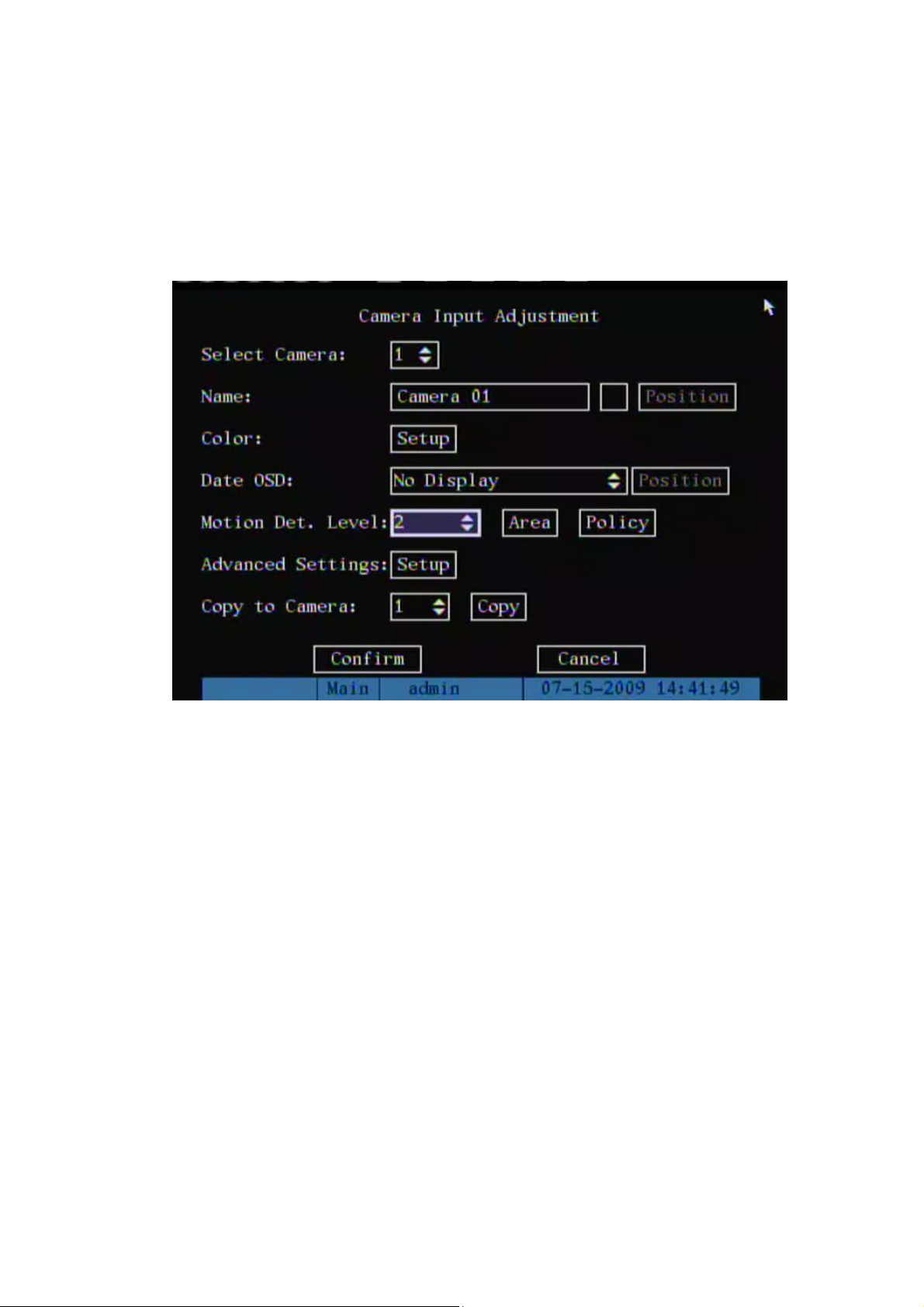
5.5.1 Camera Name Setup
Camera Name
In “Image Setup” menu, you can define name for each camera. Please notice that
camera’s name can not be copied.
The steps of camera name setup:
Step 1: Select one camera.
Step 2: Move “Active Frame” to camera name edit box, press [EDIT] key to enter into
edit status, you can input digital number, uppercase and lowercase characters (refer to
Chapter 3.4). The camera name can support 32 characters.
Step 3: Press [ENTER] key to exit edit status.
Move “Active Frame” to “Confirm” button, press [ENTER] to save the modification
and you can see the new camera name. Press “Cancel” button or [ESC] key to abort.
Setup Camera Name Position
If you do not want to display camera name, just disable the check box beside camera
name edit box. Blank box means disable. If you enable the check box, you can setup the
camera name position. You can copy the position to any other camera. The setup steps

68
are:
Step 1: Enter into “Image Setup” menu.
Step 2: Select one camera.
Step 3: Enable the check box on the right side of camera name, then you move
“Active Frame” to “Position” button, press [ENTER] to enter into camera name position
setup interface, in that interface, you can use [] [] [] [] keys to move camera name
position. When the position is fixed, press [ENTER] and return “Image Setup” menu, and
press “Confirm” button to save it. In the “Image Setup” menu, press “Cancel” button or
[ESC] key, you can abort the modification.
5.5.2 Video Parameters Setup
For different camera and different background, in order to get the best video image,
you need to adjust video parameters such as brightness, saturation, contrast and hue, etc.
You can setup the camera individually, and also you can copy the video parameters
of one camera to any other cameras. Here are the setup steps:
Step 1: Enter into “Image Setup” menu:
Step 2: Select camera: Please use [] [] keys to select one camera.
Step 3: Click “Color” setup button and enter into sub menu. Adjust brightness,
contrast, saturation and hue:

69
Move “Active Frame” to the “Adjust” button on the right side of Brightness, Contrast,
Saturation and Hue, press [ENTER] key, you will enter into the corresponding adjust
interface. In the adjust interface, there is one scroll bar at the bottom, you can use [] []
keys to adjust and can find the video image will be changed at the same time. When you
are satisfied with the real time video image, press [ENTER] to return “Image Setup” menu.
Step 4: You can copy the video parameters of current camera to any other cameras.
Or you can repeat setp2 and step3 to adjust for any other camera.
After adjust, in “Image Setup” menu, press “Confirm” button to save parameters and
make them into effective. Otherwise, press “Cancel” button or [ESC] key to abort
modification.

70
5.6 Mask Area Setup
In some cases, maybe you want mask the sensitive area. This area will not be
preview and recorded. The mask area setup steps are following:
Step 1: Enter into “Image Setup” menu:
Step 2: Select one camera: You can use [] [] keys to select one camera.
Step 3: Click “Advanced settings” setup menu:
Step4: Enable “Privacy Mask” option, click “Area” button to enter into mask
area setup interface:
Enable the check box beside “Privacy Mask” item, you can press [EDIT] key to
change the flag into “”, and active “Area” button. Move “Active Frame” to “Area” button
on the right side of mask check box, press [ENTER] key to enter into mask area setup
interface.

71
Step 5: Setup mask area: In the mask area setup interface, there is one small yellow
pane on the upper left side. For PAL camera, the whole screen is divided into 22*18 panes
(22*15 for NTSC), you can use [] [] [] [] keys to move the yellow pane to your
hope position and press [EDIT] key, the yellow pane will be turned into red, then you can
use [] [] [] [] keys to extend the red pane. This red area is the mask area.
After setting the red mask area, you can press [EDIT] key to save. Press [ESC] key
to cancel the mask area. The maximum mask area size is 8*8 panes and the minimum
size is only one pane. You can setup 4 mask areas at most.
After you finish setup, press [ENTER] key to return “Image Setup” menu. You can
press [A] key to clear all mask areas.
Step 6: Save mask area: You can repeat step2, step3 and step4 to setup mask area
for other cameras. In “Image Setup” menu, press “Confirm” button to save the mask area,
press “Cancel” button to abort.

72
5.7 View Tampering Alarm
If you enable this function, when someone blocks the camera spitefully, DVR will
make warning alarm.
Step 1: Enter into “Image Setup” menu:
Step 2: Select camera: Please use [] [] keys to select one camera.
Step 3: Enter into “Advanced settings” setup menu:
Select sensitivity: You can use [] [] keys to select the sensitivity for “View
Tampering” item. The sensitivity options are: Low, Normal and High. Selecting one of them
will active “Area Setup” and “Policy Setup” functions.
Step 4: View tampering area setup: Move “Active Frame” to “Area” button, press
[ENTER] key to enter into area setup interface. The setup methods are same as that of
mask area setup. After setting up the area, press [ENTER] key to return “Image Setup”
menu. You can press [ESC] key to abort.
Only one view tampering area can be setup.
Step 5: View tampering alarm setup In “Advanced settings” menu, move “Active
Frame” to “View tampering policy” button, press [ENTER] key to enter into “View
Tampering Handle” menu:

73
Step 6: Alarm schedule setup: When there is view tampering alarm happened,
DVR will handle the alarm based on the schedule. You can set 4 periods for each day one
week. Also you can copy the schedule of one day to other days.
Notes: Time periods can not overlap. Please reboot DVR to make the parameters into
effective.
Step 7: Setup alarm policy: If there is view tampering alarm happened during
schedule, DVR will response based on the policy. You can select one or more solution
including “On Screen Warning”, “Audible Warning”, “send Email”, “Upload to Center” and
“Trigger Alarm Output”. You can use [] [] and [EDIT] key to enable or disable them.
Blank means disable and “” is enable.
Step 8: Save alarm setup: After your setup, press “Confirm” button and return
“Image Setup” interface. In “Image Setup” menu, press “Confirm” button to save current
camera parameters and return main menu.
Step 9: Save all cameras: If you want to setup other cameras, please repeat from
step2 to step 8. In “Image Setup” menu, press “Confirm” key to save all cameras
parameters. Press “Cancel” button or [ESC] key to abort.

74
5.8 Video Loss Alarm
When the video cable or camera has something wrong, the video image is lost. If you
enable video loss alarm, in such case, DVR will make alarm.
Step 1: Enter into “Image Setup” menu:
Step 2: Select camera: Use [] [] keys to select one camera.
Step 3: Enter into “Advanced settings”, enable “Signal Loss” option:
Step4: Enter into “Video Signal Loss Handle” interface:

75
Step 5: Setup alarm schedule: You can setup working schedule. Only when the
video loss is happened in the schedule, DVR will response.
Note: The 4 time periods can not overlap. Please reboot DVR to make parameters
into effective.
Step 6: Setup alarm policy: You can select one or more solution including “On
Screen Warning”, “Audible Warning”, “send Email”, “Upload to Center” and “Trigger Alarm
Output”. You can use [] [] and [EDIT] key to enable or disable them. Blank means
disable and “” is enable.
Step 7: Save alarm setup: After your setup, press “Confirm” button and return
“Image Setup” interface. In “Image Setup” menu, press “Confirm” button to save current
camera parameters and return main menu.
Step 8: Save all cameras: If you want to setup other cameras, please repeat from
step2 to step 6. In “Image Setup” menu, press “Confirm” key to save all cameras
parameters. Press “Cancel” button or [ESC] key to abort.
76
5.9 Motion Detection Alarm
If you enable this function, when there is motion detected, DVR will make alarm.
Step 1: Enter into “Image Setup” menu:
Step 2: Select camera: Use [] [] key to select one camera.
Step 3: Select motion detection sensitivity: On the right side of “Motion Det. Level”
item, there is a list box. That is motion detection sensitivity. There are 7 options, from 0
(the lowest) to 5 (the highest) and “Off”. You can use [] [] keys to select one. If you
select “Off” option, DVR will not response even if there is motion detection. If you select
other options, “Motion Area Setup” button and “Policy Setup” button will be active. If you
select low sensitivity such as 0, only when there is great motion detection, DVR can
response. On the other side, for high sensitivity such as 5, DVR will response with small
motion detection. The default sensitivity is 2.
Step 4: Motion area setup: You must define motion areas so that DVR will response
when there is motion in those areas. Move “Active Frame” to “Area” button on the right
side of sensitivity list box, press [ENTER] key, you can enter into “Motion Area Setup”

77
interface.
The whole screen is divided into 22*18 panes (NTSC: 22*15). There is one yellow
panel on the upper left side. The motion area setup steps are the same as that of mask
area setup (refer to chapter 5.6). The only differences are that you can use [PTZ] key to
set the whole screen as motion area, and multi motion areas can be defined. Press [A]
key to clear all motion areas.
Setup multi areas: After you setup one motion area, press [EDIT] key, the yellow
pane will appear again, then you can setup another motion area.
Clear motion area:
Clear part of motion area: Move the yellow pane to the start clear position of motion
area, press [EDIT], you will find the yellow pane is turned into black pane. You can use [↓]
[→] key to enlarge or shrink the black area. Press [EDIT] key to clear this part motion
area.
Press [Enter] key to save and return “Image” menu. Press [ESC] to cancel.
Clear all motion areas: Press [A] key to clear all motion areas of this channel.
The keys used to setup motion areas are following:
[↑] [↓] [←] [→]: Move yellow panel to any position;
[EDIT]:Yellow panel and red panel switch key:;
[→]: Right enlarge red pane;

78
[←]: Left shrink red pane;
[↓]: Down enlarge red pane;
[↑]: Up shrink red pane;
[PTZ]: Set whole screen as motion area;
[A]: Clear all motion areas;
[ENTER]: Save and return “Image Setup” menu;
[ESC]: Cancel setup and return “Image Setup” menu;
Step 5: Motion alarm policy: Move “Active Frame” to the corresponding “Policy”
button of motion detection alarm, press [ENTER] key to enter into “Motion Alarm Handle”
menu:
Step 6: Motion alarm record channel setup: When there is motion alarm happened,
you can trigger related camera to start recording. In “Motion Alarm Handle” menu, you can
select one or more record channels. Please use [ENTER] or [EDIT] key to enable the flag
into “”.
Note: In order to make the cameras start recording, in “Recording” menu, you must
enable recording schedule and set “Rec Type” as “Motion Detection” or “Motion | Alarm”.
Please refer to chapter 5.11 for recording setup.
Step 7: Motion alarm schedule: When the motion alarm is happened in schedule,
DVR will response such as “On Screen Warning”, “Audible Warning”, “Upload to Center”
and “Trigger Alarm Output”. You can setup 4 time periods for one day and 7 days for one

79
week.
Note: Time periods in one day can not overlap.
Step 8: Motion alarm handle method setup: You can select one or more handle
methods such as “On Screen Warning”, “Audible Warning”, “Upload to Center” and
“Trigger Alarm Output”.
Description: If “On Screen Warning” is enabled, when there is motion alarm
happened and DVR is in preview mode, DVR will pop-up the related camera. If you trigger
more than one camera, DVR will pop-up them one by one every N seconds (The value of
N dependent on the switch time in preview setup). When the motion alarm is disappeared,
DVR will restore preview mode.
Step 9: Save motion alarm setup: Press “Confirm” button to return “Image Setup”
menu. In the “Image Setup” menu, press “Confirm” button to save the current camera
parameters.
Step 10: Save all cameras: You can repeat from step2 to step8 to setup motion
detection parameters for other cameras. Also you can copy the parameters of one camera
to any other cameras.
Note: Motion alarm area can not be copied.
If you want to disable motion alarm area and motion alarm policy, you just need to
select the motion alarm sensitivity as “Off”.

80
5.10 Live View Setup
In “Display” menu, you can setup live view properties.
In “Preview” menu, you can setup select out, preview mode, screen switch time,
enable or disable audio preview and preview layout.
Select Out: Use “Select Out” to select the main or Spot outputs
Preview mode: For preview mode item, you can use [↑] [↓] key to select one mode.
If DVR has only 1 channel, you can select only “1 Screen” option. If DVR has 4 channels,
there are “1 Screen” and “4 Screen” options. If DVR has more than 4 but less than 9
channels, there are “1 Screen”, “4 Screen” and “9 Screen” options. If DVR has 16
channels, there are “1 Screen”, “4 Screen”, “9 Screen” “12 Screen” and “16 Screen”

81
options.
Dwell: That is image preview switch time. You can use [↑] [↓] keys to select switch
time. There are many options, including “5 Seconds”, “10 Seconds”, “20 Seconds”, “30
Seconds”, “1 Minutes”, “2 Minutes”, “5 Minutes” and “Never”. If you select “Never”, the
preview image will not be switched automatically. For example, for 16 channels DVR, if
you select “4 Screen” preview mode and “20 Seconds” switch time, DVR will cycle display
4 channels image every 20 seconds.
Audio enable/disable: If you enable audio preview (“”), when you preview single
camera, DVR will play the audio of that channel.
Alarm/Aux Out: This configures the monitor that will switch to full screen on alarm.
Duration: In motion detection handle menu or sensor alarm handle menu, if you
enable “On Screen Warning” option. When there is alarm happened, DVR will switch the
corresponding camera live image on screen. When there are several alarms happened,
DVR will switch camera live image one by one based on “Display Delay” time.
layout: There is a square frame divided into many windows. If you select “4 Screen”
preview mode, this frame is divided into 4 windows. Each window represents one camera.
You can move “Active Frame” among the windows. There is one bar under the square to
display the preview order of all cameras.
First select the biggest screen preview mode, for example, for 16-channel DVR,
select “16 Screen” preview mode so that all windows are display in the square.
Secondly, move “Active Frame” to one of these windows, press [Enter] or [EDIT] key
to enter into “Edit” status, then press numeric keys to input camera index (If DVR has less
than 10 channels, just use one numeric key, otherwise, use 2 numeric keys). The small
window will display that camera number. In this way you can change the display order. If
you press 0 or 00, then the corresponding window will not display live video.

82
After you define the camera preview order, you can select preview mode to meet your
demand.
Save setup: Press “Confirm” button to confirm preview configuration and return
“Display” menu, press “Confirm” button to save changed parameters. Press “Cancel” or
[ESC] key to abort.
You can press [PREV] button to enter into live preview and change preview screen
mode.
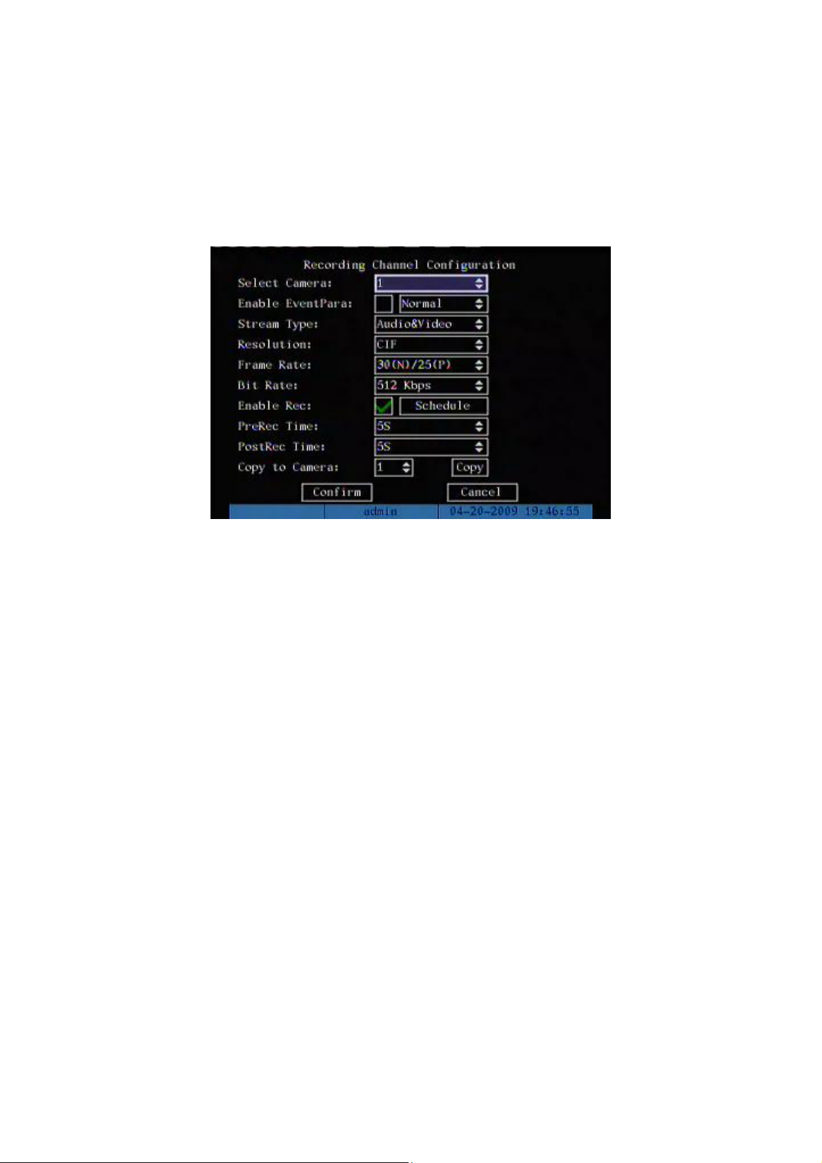
83
5.11 Recording Setup
In main menu, there is an icon named “Recording”. You can enter into recording
menu as following:
Recording menu description:
Select Camera: Here all channels are listed. You can use [↑][↓] keys to select one.
Enable eventPara: Enable this function can set two types of recording parameters.
When event happens, the record parameters will be changed.
Stream Type: There are two options, one is “Audio&Video” stream and the other is
“Video” stream only. If you want to record video and audio, please select “Audio&Video”
option, otherwise you can select “Video” option to record only video.
Note: If you change this option, please reboot DVR to make parameter into effective.
Resolution: The higher resolution is, the clearer the image is. The resolution options
from low to high are: QCIF, CIF, 2CIF, DCIF, 4CIF.
For DS-8700HI series DVR: Can support QCIF/CIF/2CIF real time recording,
DCIF@15FPS, 4CIF@12FPS recording.
Note: If you change this resolution option, please reboot DVR to make it into effective.
Bit Rate: For different resolution, different frame rate, you can select different bit rate.
The bit rate value has following options (bps): 32K, 48K, 64K, 80K, 96K, 128K, 160K,
192K, 224K, 256K, 320K, 384K, 448K, 512K, 640K, 768K, 896K, 1M, 1.25M, 1.5M, 1.75M,

84
2M and “User define”.
The max bit rate selection has relations with resolution. If you select high resolution,
you must select high bit rate. For CIF resolution, the typical max bit rate is 384K~768Kbps
for real time compression. For 2CIF/DCIF resolution, the typical bit rate is 512K~1Mbps
real time compression. For 4CIF resolution, the typical bit rate is 1.25Mbps~1.75Mbps for
real time compression. Of course, you will select the proper bit rate based on the camera,
background and image quality requirement.
Frame Rate: Frame per second. Options are: Full (PAL is 25 FPS and NTSC is
30FPS), 20, 16, 12, 10, 8, 6, 4, 2, 1, 1/2, 1/4, 1/8, 1/16. For low frame rate, you can select
low bit rate size.
PreRecord Time: When you enable motion detection recording or external alarm
recording, you can define prerecord time. The options are: No PreRecord, 5 Seconds
(default selection), 10 Seconds, 15 Seconds, 20 Seconds, 25 Seconds, 30 Seconds and
Max PreRecord.
MaxPreRecord is to save all data in PreRecord buffer. The PreRecord time is related
with bit rate. The lower bit rate, the longer PreRecord time is.
If the bit rate (Max bit rate) is very low, and you select “PreRecord Time” as “5
Seconds”, maybe the actual perrecord time is more than 5 seconds. On the other side, if
the bit rate is high, and set “PreRecord Time” as “30 Seconds”, the actual prerecord time
maybe is less than 30 seconds.
PostRecord Time: When external alarm or motion alarm is stopped, DVR will
continue recording time. The options are: 5 Seconds (default), 10 Seconds, 30 Seconds, 1
Minute, 2 Minutes, 5 Minutes and 10 Minutes.
Enable Rec: Enable or disable selected camera record function. Blank box means
disable and “” means enable.
Schedule: When you enable recording function, you can setup recording schedule.
Note: When the camera’s recording schedule is modified, you must reboot DVR to
make it into effective.
All day recording setup:
Step 1: Enter into recording schedule menu

85
In recording menu, use [ENTER] or [EDIT] key to enable record function (“” flag),
press “Schedule” button to enter into recording schedule menu.
Step 2: Select one day and enable all day recording option
For “Day” item, there are options: Monday, Tuesday, Wednesday, Thursday, Friday,
Saturday and Sunday. Use [↑] [↓] keys to select one day. Move “Active Frame” to the
check box on the right side of “All Day” item, press [ENTER] or [EDIT] key to enable “All
Day” option. Blank box means disable and “” means enable.
Step 3: Record type
For “Rec Type” item, the options are: All Time, Motion Detect, Alarm, Motion|Alarm,
and Motion&Alarm.
For all day record mode, only one record type can be selected.
Step 4: Copy to other days
You can repeat step2 and step3 to setup for other days. Also you can copy the
current day to other days.
Step 5: Save
Press “Confirm” back to “Recording” menu. Press “Confirm” again to save the
parameters and return main menu.
Scheduled recording setup
Step 1: Enter into recording schedule menu
In recording menu, use [ENTER] or [EDIT] key to enable record function (“” flag),

86
press “Schedule” button to enter into recording schedule menu.
Step 2: Select one day and disable all day recording option
For “Day” item, there are options: Monday, Tuesday, Wednesday, Thursday, Friday,
Saturday and Sunday. Use [↑] [↓] keys to select one day. Move “Active Frame” to the
check box on the right side of “All Day” item, press [ENTER] or [EDIT] key to disable “All
Day” option. Blank box means disable and “” means enable.
Step 3: Setup time period and record type
There are 4 time periods for one day, and each time period can select different record
type. Input start time and stop time for each time period, and select record type for each
period. The record type options are: All Time, Motion Detect, Alarm, Motion&Alarm and
Motion|Alarm.
Note: The time periods in one day can not overlap.
Step 4: Copy to other days
You can repeat step2 and step3 to setup for other days. Also you can copy the
current day to other days.
Step 5: Save
Press “Confirm” back to “Recording” menu. Press “Confirm” again to save the
parameters and return main menu.

87
Note:
1) If record type is “Motion Detect” or other related types, you must setup “Motion
Detection” in order to trigger motion recording (refer to chapter 5.9).
2) If record type is “Alarm” or other related types, you must setup “Alarms” in
order to trigger alarm recording (refer to chapter 5.12).
3) The time period is among 00:00—24:00.

88
5.12 Alarm I/O Setup
For 4-channel DVR, there are 4 external alarm input and 2 relay output. For 8 or
16-channel DVR, there are 16 external alarm input and 4 relay output.
Note: For 8704HI-S is 4 external alarm input and 2 relay output.
In “Alarms” menu, you can setup each external alarm input.
In main menu, move “Active Frame” to “Alarms” icon and press [ENTER] key to enter
into alarms menu:
External alarm input setup:
Step 1: Select one alarm input Use [↑] [↓] keys to select one alarm input. You can
change the Alarm in Name in box “Alarm In Name”
Step 2: Alarm type
This is sensor type. You can select “Normal Open” or “Normal Close” according to the
sensor type.
Step 3: Enter into “Alarm in Handling” sub menu
In the “Alarms” menu, there are two options for “Alarm Handling” item. One is “Ignore”,
and the other is “Handle”. If you select “Handle” option, you can active “Policy” and “PTZ
Linkage” buttons on right side. Move “Active Frame” to “Policy” button and press [ENTER]
key, you will enter into “Alarm in Handling” sub menu:

89
Step 4: Alarm trigger record channel setup
You can select channels to record for each alarm input. In the sub menu, you can use
[ENTER] or [EDIT] key to enable record channel. “” means enable.
Note: In order to trigger the channel to record, in “Recording” menu, you must enable
recording and select record type as “Alarm” or other related type. Please refer to chapter
5.11.
Step 5: Schedule for alarm handle method
When there is external alarm happened in the schedule, DVR will response according
to the handle methods.
Step 6: Alarm handle method
You can select one or more handle method: “On Screen Warning”, “Audible Warning”,
“send Email”, “Upload to Center” and “Trigger Alarm Output”.
Description: If “On Screen Warning” is enabled, when there is external alarm
happened and DVR is in preview mode, DVR will pop-up the related camera. If you trigger
more than one camera, DVR will pop-up them one by N seconds (The value of N
dependent on the switch time in preview setup). When the external alarm is disappeared,
DVR will restore preview mode.
Step 7: Save setup
In “Alarm in Handling” sub menu, press “Confirm” button and return “Alarms” menu. In

90
“Alarms” menu, press “Confirm” button to save the parameters.
Step 8: PTZ Linkage
Move “Active Frame” to “PTZ Linkage” button, press [ENTER] key to enter into “PTZ
Linkage” setup menu:
First select one camera, then select one of following PTZ linkage:
Preset: Set the flag as “” to enable preset, in the preset number edit box and
input one preset number that has been setup already. Please refer to chapter
5.14 for preset setup.
Sequence: Set the flag as “” to enable sequence and input one sequence
number that has been setup already. Please refer to chapter 5.14 for sequence
setup.
Tour: Set the flag as “” to enable Tour. Please refer to chapter 5.14 for Tour
setup.
Press “Confirm” button to save and return “Alarms” menu. Press “Cancel” button or
[ESC] key to abort and return “Alarms” menu.
Note: Please make sure that the PTZ you are using can support preset, sequence
and Tour functions. Also make sure that you setup them in PTZ menu. One external alarm
input can trigger many cameras PTZ linkage.
Step 9: Copy the parameters to other external alarm input You can copy the

91
parameters of current alarm input to other external input.
Step 10: Save setup In “Alarms” menu, press “Confirm” button to save the
parameters. Press “Cancel” button or [ESC] key to abort.
Alarm relay output setup
Step 1: In “Alarms” menu, use [↑] [↓] keys to select one alarm output.
Step 2: Select delay time
The delay time is when the alarm is disappeared, the alarm output will continue
output time. The delay time options are: 5 Seconds, 10 Seconds, 30 Seconds, 1 Minute, 2
Minutes, 5 Minutes, 10 Minutes and Manual Stop. If you select “Manual’ option, the alarm
output will not stop until you press “Clear Alarm” button in “Utilities” menu. So the actual
alarm output time is made up of alarm input time and this delay time.
Step 3: Enter into alarm out schedule
You can set the schedule to make alarm output into effective. Move “Active Frame” to
“Schedule” button on right side of “Alarm Out Time” item, press[ENTER] key to enter into
the corresponding schedule menu:
Step 4: Setup alarm out schedule
Like other schedule setup, you can set 4 time periods for one day and 7 days for one
week. When you finish setup, press “Confirm” button to return “Alarms” menu.
Step 5: Copy one alarm output parameters to other alarm output

92
In “Alarms” menu, you can copy parameters of current alarm output to other alarm
output.
Step 6: Save setup
When you finish setup, in “Alarms” menu, press “Confirm” button to save all
parameters.
Note: If any schedule is modified, you must reboot DVR to make it into effective.

93
5.13 Network Setup
If you want to get access to DVR via network, you must setup network parameters.
Note: If any network parameter is modified, you must save and reboot DVR to make it
into effective.
In main menu, move “Active Frame” to “Network” icon and press [ENTER], you can
enter into “Network” menu as following:
5.13.1 Network Basic Settings
IP: This IP address must not be conflict with other IP. If there is DHCP server in
network, you can set the IP as “0.0.0.0”, save and reboot DVR. In reboot process, DVR
will search the DHCP server and get one dynamic IP address. This item will display the
dynamic IP address. If DVR uses PPPoE function, also DVR can dialup into internet and
this item will display the dynamic internet IP address.
Port: Network access port number, must be greater than 2000.
Mask: This is sub net mask.
Gateway: The gateway IP is used to communicate in different network segments

94
5.13.2 Network Advanced Settings
NIC type: Default is “10M/100M Auto”, the other options are: 10M Half-Dup, 10M
Full-Dup, 100M Half-Dup and 100M Full-Dup.
Multicast IP: It is one D-class IP address, among 224.0.0.0 --- 239.255.255.255. If
you do not use multicast function, you do not need to set. Some routers will prohibit
multicast function in case of network storm.
Remote Host IP and Port: If you set this IP and port and enable “Upload to Center”
option, when there is alarm and exception happened, DVR will send information to that
host IP. The center with this IP can receive alarm and exception information from DVR.
You can use SDK to develop this center software.
Http Port: The port is for IE browser. The default value is 80. It can be modified.
NTP: Network time Protocol
5.13.3 DHCP Function
In DVR “Network” menu, if you set the IP as “0.0.0.0”, save and reboot DVR, in reboot
process, DVR will search the DHCP server and get one dynamic IP address. This item will
display the dynamic IP address.

95
5.13.4 PPPoE Function
Enter into DVR “Network” menu, press “PPPoE” setup menu:
Step 1: Enable “PPPoE” option
Step 2: Input PPPoE username which is from ISP
Step 3: Input PPPoE password which is from ISP
Step 4: Input PPPoE password again
Step 5: Save parameters. In “PPPoE” menu, press “Confirm” to save parameters,
press “Confirm” again in “Network” menu. Reboot DVR to make parameters into effect. In
reboot process, DVR will start dialup using PPPoE parameters. If DVR dialup internet
successfully, DVR will display the dynamic internet IP address in “Network” menu.

96
5.13.5 IP Server Solution for DHCP
If DVR uses PPPoE function, and get one dynamic Internet IP address. If you set IP
server with one fixed Internet IP in DVR Network advanced settings, DVR will send some
information such as DVR name, DVR serial number, DVR current IP to that fixed IP
address. We call that fixed Internet IP as IP server. The IP server with that fixed Internet IP
can receive DVR information and used to resolve DVR dynamic IP.
To use the IP server function you have to select HIKVISION protocol in DDNS setup
menu.
IP server is one software run in the computer, also you can use the provided SDK to
develop this IP server software.
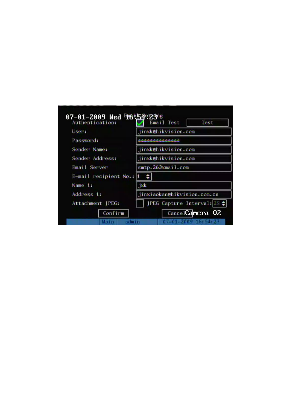
97
5.13.6 DDNS setup
If you enable DDNS function, there are some protocols provide such as: IPServer, cn99,
PeanutHull and DynDns.
5.13.7 Email setup
This section setup E-mail:
Authentication: If your Email server asks for a user name and password when you send Email,
you need to tick this check box
User: Email account user name
Password: Email account password
Sender Name: Name appears in Email
Sender Address: Sender Email address
Email server: SMTP supported Email sending server
Name 1: Mail receiver name, the name appears in Email
Name 2: Mail receiver address, Receiver Email address
Attachment JPEG: Sending the Email with JPEG picture capture when there is an alarm
Test: Test the configuration whether it is correct.
5.14 PTZ Setup
There is one RS-485 port at DVR rear panel used for PTZ control.
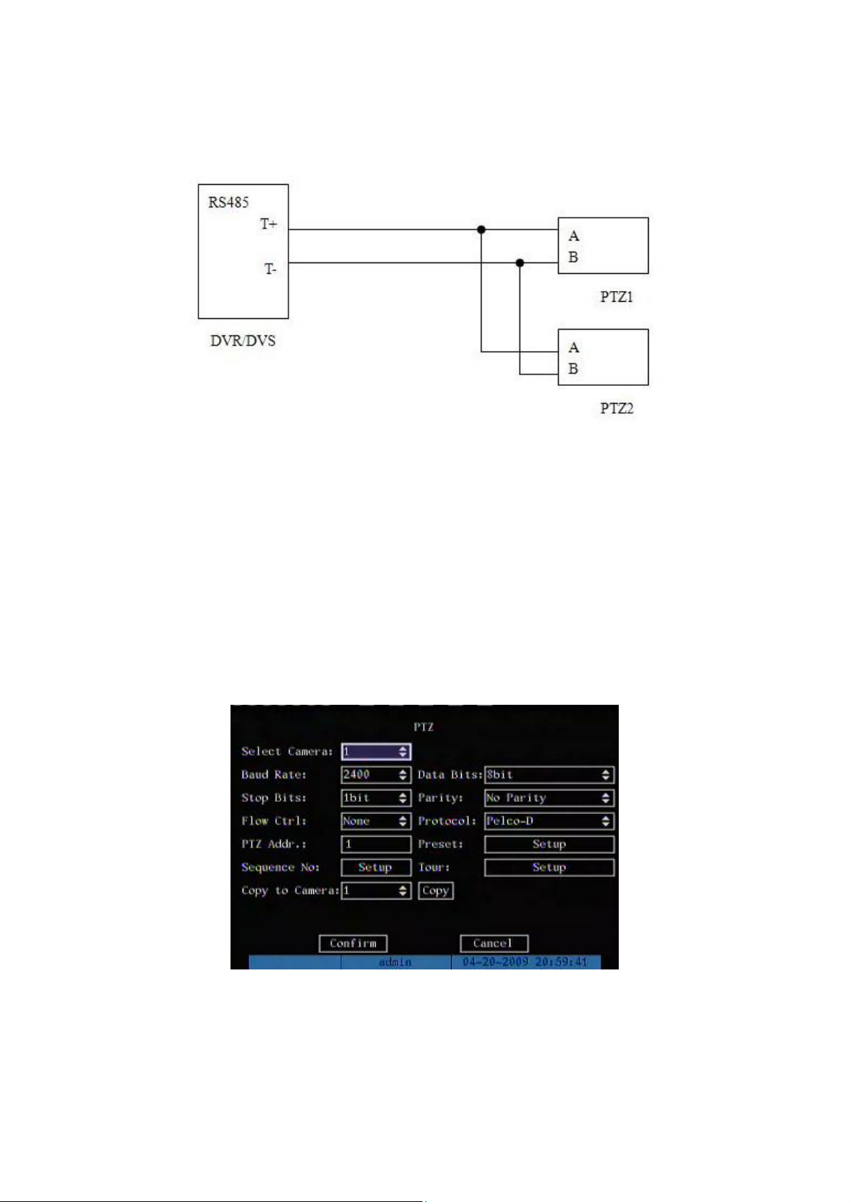
98
5.14.1 PTZ Connection
Connect DVR/DVS RS-485 port Pin “T+” with PTZ Pin “A”.
Connect DVR/DVS RS-485 port Pin “T-“ with PTZ Pin “B”.
If DVR/DVS RS-485 port is RJ45 interface, please refer to DVR/DVS user manual
about RS-485 pin definition.
5.14.2 PTZ Settings
You can setup RS-485 parameters to match your PTZ protocol. In main menu, move
“Active Frame” to PTZ menu item and press [ENTER] key, you can enter into PTZ menu
as following:
PTZ menu description
Select channel: Select one PTZ camera.
RS-485 parameters: Including baud rate, data bit, stop bit, parity, flow control, etc.

99
These parameters must be the same as those of PTZ protocol.
PTZ address: Each PTZ has one different address.
PTZ type: DVR had the following PTZ protocol: YouLi, LinLin-1016, LinLin-820,
Pelco-p, DM DynaColor, HD600, JC-4116, Pelco-d WX, Pelco-D, VCOM VC-2000,
NetStreamer, SAE/YAAN, Samsung, Kalatel-312, CELOTEX, TLPelco-p, TLHHX-2000,
BBV, RM110, KC3360S, ACES, ALSON, INV3609HD, Howell, Tc Pelco P, Tc Pelco D,
AUTO-M, AUTO-H, ANTEN, CHANGLIN, DeltaDome, XYM-12, ADR8060, EVI-D30,
DEMO-SPEED, DM-PELCO-D, ST832, LC-D2104, HUNTER, A01, TECHYIN, WEIHAN,
LG, D-MAX, Panasonic, KTD-348, infinova, PIH-7625, LCU, DennarDome, etc. Other PTZ
protocols will be added with the new firmware.
Note: In DVR “PTZ” menu, if you select Pelco-P protocol, when you setup PTZ
address, please plus or minus one compared with Camera ID. For example, if camera ID
is 2, the DVR PTZ address is set as ID 3.
Please reboot DVR when you change PTZ parameters.
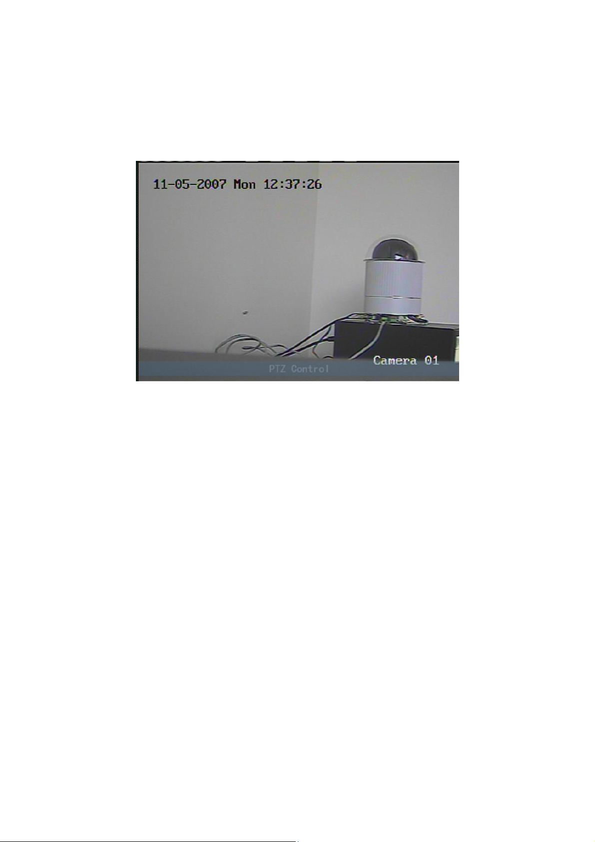
100
5.14.3 PTZ Control
In “Preview” mode, press [PTZ] button on DVR front panel, you can enter into PTZ
control mode.
For example, above screen is in camera01 PTZ control mode. Press
[UP][DOWN][LEFT][RIGHT] buttons, DVR will check camera01 PTZ protocol and will
send corresponding PTZ control commands through RS-485 port.
5.14.4 Preset Setup
Preset is using one number to represent the camera’s position, zoom, focus and
iris. Move “Active Frame” to “Setup” button on the right side of “Preset” item, press
[ENTER] key to enter into preset setup menu. You can save 128 preset numbers. Please
make sure the PTZ support preset function before you setup preset.
 Loading...