


Hikvision DS-2TD2235D-25, DS-2TD2235D-50 User Manual
Thermal + Optical Bi-spectrum
Network Bullet Camera
User Manual
UD.6L0201D2075A01

User Manual of Thermal + Optical Bi-spectrum Network Bullet Camera
User Manual
COPYRIGHT ©2015 Hangzhou Hikvision Digital Technology Co., Ltd.
ALL RIGHTS RESERVED.
Any and all information, including, among others, wordings, pictures, graphs are the properties of Hangzhou Hikvision Digital Technology Co., Ltd. or its subsidiaries
(hereinafter referred to be “Hikvision”). This user manual (hereinafter referred to be “the Manual”) cannot be reproduced, changed, translated, or distributed, partially or wholly, by any means, without the prior written permission of Hikvision. Unless otherwise stipulated, Hikvision does not make any warranties, guarantees or representations, express or implied, regarding to the Manual.
About this Manual
This Manual is applicable to Thermal + Optical Bi-spectrum Network Bullet Camera (V5.3.2)
The Manual includes instructions for using and managing the product. Pictures, charts, images and all other information hereinafter are for description and explanation only. The information contained in the Manual is subject to change, without notice, due to firmware updates or other reasons. Please find the latest version in the company website (http://overseas.hikvision.com/en/).
Please use this user manual under the guidance of professionals.
Trademarks Acknowledgement
and other Hikvision’s trademarks and logos are the properties of
Hikvision in various jurisdictions. Other trademarks and logos mentioned below are the properties of their respective owners.
Legal Disclaimer
TO THE MAXIMUM EXTENT PERMITTED BY APPLICABLE LAW, THE PRODUCT DESCRIBED, WITH ITS HARDWARE, SOFTWARE AND
FIRMWARE, IS PROVIDED “AS IS”, WITH ALL FAULTS AND ERRORS, AND
HIKVISION MAKES NO WARRANTIES, EXPRESS OR IMPLIED, INCLUDING
2

User Manual of Thermal + Optical Bi-spectrum Network Bullet Camera
WITHOUT LIMITATION, MERCHANTABILITY, SATISFACTORY QUALITY, FITNESS FOR A PARTICULAR PURPOSE, AND NON-INFRINGEMENT OF THIRD PARTY. IN NO EVENT WILL HIKVISION, ITS DIRECTORS, OFFICERS, EMPLOYEES, OR AGENTS BE LIABLE TO YOU FOR ANY SPECIAL, CONSEQUENTIAL, INCIDENTAL, OR INDIRECT DAMAGES, INCLUDING, AMONG OTHERS, DAMAGES FOR LOSS OF BUSINESS PROFITS, BUSINESS INTERRUPTION, OR LOSS OF DATA OR DOCUMENTATION, IN CONNECTION WITH THE USE OF THIS PRODUCT, EVEN IF HIKVISION HAS BEEN ADVISED OF THE POSSIBILITY OF SUCH DAMAGES.
REGARDING TO THE PRODUCT WITH INTERNET ACCESS, THE USE OF PRODUCT SHALL BE WHOLLY AT YOUR OWN RISKS. HIKVISION SHALL NOT TAKE ANY RESPONSIBILITES FOR ABNORMAL OPERATION, PRIVACY LEAKAGE OR OTHER DAMAGES RESULTING FROM CYBER ATTACK, HACKER ATTACK, VIRUS INSPECTION, OR OTHER INTERNET SECURITY RISKS; HOWEVER, HIKVISION WILL PROVIDE TIMELY TECHNICAL SUPPORT IF REQUIRED.
SURVEILLANCE LAWS VARY BY JURISDICTION. PLEASE CHECK ALL RELEVANT LAWS IN YOUR JURISDICTION BEFORE USING THIS PRODUCT IN ORDER TO ENSURE THAT YOUR USE CONFORMS THE APPLICABLE LAW. HIKVISION SHALL NOT BE LIABLE IN THE EVENT THAT THIS PRODUCT IS USED WITH ILLEGITIMATE PURPOSES.
IN THE EVENT OF ANY CONFLICTS BETWEEN THIS MANUAL AND THE APPLICABLE LAW, THE LATER PREVAILS.
Regulatory Information
FCC Information
FCC compliance: This equipment has been tested and found to comply with the limits for a digital device, pursuant to part 15 of the FCC Rules. These limits are designed to provide reasonable protection against harmful interference when the equipment is operated in a commercial environment. This equipment generates, uses,
3

User Manual of Thermal + Optical Bi-spectrum Network Bullet Camera
and can radiate radio frequency energy and, if not installed and used in accordance with the instruction manual, may cause harmful interference to radio communications. Operation of this equipment in a residential area is likely to cause harmful interference in which case the user will be required to correct the interference at his own expense.
FCC Conditions
This device complies with part 15 of the FCC Rules. Operation is subject to the following two conditions:
1.This device may not cause harmful interference.
2.This device must accept any interference received, including interference that may cause undesired operation.
EU Conformity Statement
This product and - if applicable - the supplied accessories too are marked with "CE" and comply therefore with the applicable harmonized European standards listed under the EMC Directive
2004/108/EC, the RoHS Directive 2011/65/EU.
2012/19/EU (WEEE directive): Products marked with this symbol cannot be disposed of as unsorted municipal waste in the European Union. For proper recycling, return this product to your local supplier upon the purchase of equivalent new equipment, or dispose of it at designated collection points. For more information see:
www.recyclethis.info.
2006/66/EC (battery directive): This product contains a battery that cannot be disposed of as unsorted municipal waste in the European Union. See the product documentation for specific battery information. The battery is marked with this symbol, which may include lettering to indicate cadmium (Cd), lead (Pb), or mercury
(Hg). For proper recycling, return the battery to your supplier or to a designated collection point. For more information see: www.recyclethis.info.
4

User Manual of Thermal + Optical Bi-spectrum Network Bullet Camera
Industry Canada ICES-003 Compliance
This device meets the CAN ICES-3 (A)/NMB-3(A) standards requirements.
Safety Instruction
These instructions are intended to ensure that the user can use the product correctly to avoid danger or property loss.
The precaution measure is divided into ‘Warnings’ and ‘Cautions’:
Warnings: Serious injury or death may be caused if any of these warnings are neglected.
Cautions: Injury or equipment damage may be caused if any of these cautions are neglected.
Warnings Follow these safeguards to Cautions Follow these precautions to prevent serious injury or death. prevent potential injury or material
damage.
 Warnings:
Please adopt the power adapter which can meet the safety extra low voltage (SELV) standard. And source with 12 VDC or 24 VAC (depending on models) according to the IEC60950-1 and Limited Power Source standard.
To reduce the risk of fire or electrical shock, do not expose this product to rain or moisture.
This installation should be made by a qualified service person and should conform to all the local codes.
Please install blackouts equipment into the power supply circuit for convenient supply interruption.
Please make sure that the ceiling can support more than 50(N) Newton gravities if the camera is fixed to the ceiling.
If the product does not work properly, please contact your dealer or the nearest service center. Never attempt to disassemble the camera yourself. (We shall not assume any responsibility for problems caused by unauthorized repair or maintenance.)
5

User Manual of Thermal + Optical Bi-spectrum Network Bullet Camera
 Cautions:
Make sure the power supply voltage is correct before using the camera.
Do not drop the camera or subject it to physical shock.
Do not touch sensor modules with fingers. If cleaning is necessary, use a clean cloth with a bit of ethanol and wipe it gently. If the camera will not be used for an extended period of time, put on the lens cap to protect the sensor from dirt.
Do not aim the camera lens at the strong light such as sun or incandescent lamp. The strong light can cause fatal damage to the camera.
The sensor may be burned out by a laser beam, so when any laser equipment is being used, make sure that the surface of the sensor not be exposed to the laser beam.
Do not place the camera in extremely hot, cold temperatures (the operating temperature should be between -40°C ~ 65°C), dusty or damp environment, and do not expose it to high electromagnetic radiation.
To avoid heat accumulation, good ventilation is required for a proper operating environment.
Keep the camera away from water and any liquid.
While shipping, the camera should be packed in its original packing.
Improper use or replacement of the battery may result in hazard of explosion.
Please use the manufacturer recommended battery type.
Notes:
For the camera supports IR, you are required to pay attention to the following precautions to prevent IR reflection:
Dust or grease on the dome cover will cause IR reflection. Please do not remove the dome cover film until the installation is finished. If there is dust or grease on the dome cover, clean the dome cover with clean soft cloth and isopropyl alcohol.
Make certain the installation location does not have reflective surfaces of objects too close to the camera. The IR light from the camera may reflect back into the lens causing reflection.
The foam ring around the lens must be seated flush against the inner surface of the bubble to isolate the lens from the IR LEDS. Fasten the dome cover to camera body so that the foam ring and the dome cover are attached seamlessly.
6

User Manual of Thermal + Optical Bi-spectrum Network Bullet Camera
Table of Contents
Chapter 1 |
System Requirement .......................................................................... |
10 |
|
Chapter 2 |
Network Connection.......................................................................... |
11 |
|
2.1 |
Setting the Network Camera over the LAN...................................................... |
11 |
|
2.1.1 |
Wiring over the LAN ....................................................................................................... |
11 |
|
2.1.2 |
|
Activating the Camera .................................................................................................... |
12 |
2.2 |
Setting the Network Camera over the WAN .................................................... |
18 |
|
2.2.1 |
|
Static IP Connection........................................................................................................ |
18 |
2.2.2 |
|
Dynamic IP Connection................................................................................................... |
19 |
Chapter 3 |
Access to the Network Camera........................................................... |
22 |
|
3.1 |
Accessing by Web Browsers............................................................................ |
22 |
|
3.2 |
Accessing by Client Software .......................................................................... |
24 |
|
Chapter 4 |
Live View .......................................................................................... |
26 |
|
4.1 |
Live View Page............................................................................................... |
26 |
|
4.2 |
Starting Live View .......................................................................................... |
27 |
|
4.3 |
Recording and Capturing Pictures Manually .................................................... |
28 |
|
4.4 |
Operating PTZ Control .................................................................................... |
28 |
|
4.4.1 |
|
PTZ Control Panel............................................................................................................ |
29 |
4.4.2 |
|
Setting/Calling a Preset................................................................................................... |
30 |
4.4.3 |
|
Setting/Calling a Patrol ................................................................................................... |
31 |
Chapter 5 |
Network Camera Configuration ........................................................ |
32 |
|
5.1 |
Configuring Local Parameters ......................................................................... |
32 |
|
5.2 |
Configuring Time Settings .............................................................................. |
34 |
|
5.3 |
Configuring Network Settings ......................................................................... |
36 |
|
5.3.1 |
|
Configuring TCP/IP Settings ............................................................................................ |
36 |
5.3.2 |
|
Configuring Port Settings ................................................................................................ |
37 |
5.3.3 |
|
Configuring PPPoE Settings............................................................................................. |
38 |
5.3.4 |
|
Configuring DDNS Settings.............................................................................................. |
39 |
5.3.5 |
|
Configuring SNMP Settings ............................................................................................. |
42 |
5.3.6 |
|
Configuring 802.1X Settings............................................................................................ |
44 |
5.3.7 |
|
Configuring QoS Settings ................................................................................................ |
45 |
5.3.8 |
|
Configuring UPnP™ Settings ........................................................................................... |
46 |
5.3.9 |
Email Sending Triggered by Alarm .................................................................................. |
46 |
|
5.3.10 |
Configuring NAT (Network Address Translation) Settings............................................... |
48 |
|
5.3.11 |
Configuring FTP Settings ................................................................................................. |
49 |
|
5.3.12 |
HTTPS Settings ................................................................................................................ |
51 |
|
5.4 |
Configuring Video and Audio Settings............................................................. |
53 |
|
|
|
|
7 |

User Manual of Thermal + Optical Bi-spectrum Network Bullet Camera
5.4.1 |
Configuring Video Settings ............................................................................................. |
53 |
5.4.2 |
Configuring Audio Settings ............................................................................................. |
55 |
5.4.3 |
Configuring ROI Encoding ............................................................................................... |
56 |
5.5 |
Configuring Image Parameters........................................................................ |
57 |
5.5.1 |
Configuring Display Settings ........................................................................................... |
57 |
5.5.2 |
Configuring OSD Settings ................................................................................................ |
64 |
5.5.3 |
Configuring Text Overlay Settings ................................................................................... |
66 |
5.5.4 |
Configuring Privacy Mask................................................................................................ |
67 |
5.5.5 |
Configuring Picture Overlay ............................................................................................ |
68 |
5.5.6 |
Configuring DPC (Defective Pixel Correction) ................................................................. |
69 |
5.6 |
Configuring and Handling Alarm Events .......................................................... |
70 |
5.6.1 |
Configuring Motion Detection ........................................................................................ |
70 |
5.6.2 |
Configuring Video Tampering Alarm .............................................................................. |
77 |
5.6.3 |
Configuring Alarm Input ................................................................................................. |
78 |
5.6.4 |
Configuring Alarm Output .............................................................................................. |
79 |
5.6.5 |
Handling Exception ......................................................................................................... |
80 |
5.6.6 |
Configuring Audio Exception Detection.......................................................................... |
81 |
5.6.7 |
Configuring Dynamic Fire Source Detection ................................................................... |
82 |
5.7 |
VCA Configuration.......................................................................................... |
84 |
|
5.7.1 |
|
VCA Information ............................................................................................................. |
84 |
5.7.2 |
|
Behavior Analysis............................................................................................................ |
85 |
Chapter 6 |
Storage Settings................................................................................. |
93 |
|
6.1 |
Storage Management..................................................................................... |
93 |
|
6.2 |
Configuring NAS Settings................................................................................ |
93 |
|
6.3 |
Configuring Recording Schedule ..................................................................... |
96 |
|
6.4 |
Configuring Snapshot Settings ...................................................................... |
101 |
|
Chapter 7 |
Playback ......................................................................................... |
103 |
|
Chapter 8 |
Log Searching................................................................................. |
105 |
|
Chapter 9 |
Others ............................................................................................. |
106 |
|
9.1 |
Managing User Accounts .............................................................................. |
106 |
|
9.2 |
Authentication............................................................................................. |
108 |
|
9.3 |
Anonymous Visit.......................................................................................... |
109 |
|
9.4 |
IP Address Filter........................................................................................... |
110 |
|
9.5 |
Security Service ........................................................................................... |
112 |
|
9.6 |
Viewing Device Information ......................................................................... |
112 |
|
9.7 |
Maintenance ............................................................................................... |
113 |
|
9.7.1 |
|
Rebooting the Camera .................................................................................................. |
113 |
|
|
|
8 |

User Manual of Thermal + Optical Bi-spectrum Network Bullet Camera
9.7.2 |
Restoring Default Settings............................................................................................. |
113 |
9.7.3 |
Exporting/Importing Configuration File ....................................................................... |
114 |
9.7.4 |
Upgrading the System................................................................................................... |
115 |
9.8 |
RS-485 Settings ............................................................................................ |
115 |
9.9 |
Service Settings............................................................................................ |
116 |
Appendix |
........................................................................................................... |
117 |
Appendix 1 SADP Software Introduction ............................................................... |
117 |
|
Appendix 2 Port Mapping ...................................................................................... |
120 |
|
9

User Manual of Thermal + Optical Bi-spectrum Network Bullet Camera
Chapter 1 System Requirement
Operating System: Microsoft Windows XP SP1 and above version/Vista/Win7/Server 2003/Server 2008 32bits
CPU: Intel Pentium IV 3.0 GHz or higher
RAM: 1G or higher
Display: 1024×768 resolution or higher
Web Browser: Internet Explorer 6.0 and above version, Apple Safari 5.02 and above version, Mozilla Firefox 3.5 and above version and Google Chrome8 and above version.
10
User Manual of Thermal + Optical Bi-spectrum Network Bullet Camera
Chapter 2 Network Connection
Note:
You shall acknowledge that the use of the product with Internet access might be under network security risks. For avoidance of any network attacks and information leakage, please strengthen your own protection. If the product does not work properly, please contact with your dealer or the nearest service center.
To ensure the network security of the network camera, we recommend you to have the network camera assessed and maintained termly. You can contact us if you need such service.
Before you start:
If you want to set the network camera via a LAN (Local Area Network), please refer to Section 2.1 Setting the Network Camera over the LAN.
If you want to set the network camera via a WAN (Wide Area Network), please refer to Section 2.2 Setting the Network Camera over the WAN.
2.1 Setting the Network Camera over the LAN
Purpose:
To view and configure the camera via a LAN, you need to connect the network camera in the same subnet with your computer, and install the SADP or iVMS-4200 software to search and change the IP of the network camera.
Note: For the detailed introduction of SADP, please refer to Appendix 1.
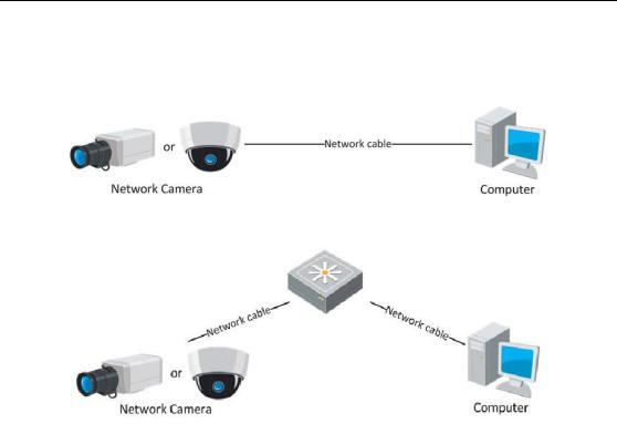
2.1.1 Wiring over the LAN
The following figures show the two ways of cable connection of a network camera and a computer:
Purpose:
To test the network camera, you can directly connect the network camera to the computer with a network cable as shown in Figure 2-1.
11
User Manual of Thermal + Optical Bi-spectrum Network Bullet Camera
Refer to the Figure 2-2 to set network camera over the LAN via a switch or a router.
Figure 2-1 Connecting Directly
Figure 2-2 Connecting via a Switch or a Router
2.1.2 Activating the Camera
You are required to activate the camera first by setting a strong password for it before you can use the camera.
Activation via Web Browser, Activation via SADP, and Activation via Client Software are all supported.
Activation via Web Browser
Steps:
1.Power on the camera, and connect the camera to the network.
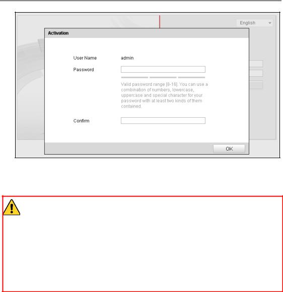
2.Input the IP address into the address bar of the web browser, and click Enter to enter the activation interface.
Notes:
The default IP address of the camera is 192.168.1.64.
For the camera enables the DHCP by default, you need to activate the camera via SADP software. Please refer to the following chapter for Activation via SADP.
12
User Manual of Thermal + Optical Bi-spectrum Network Bullet Camera
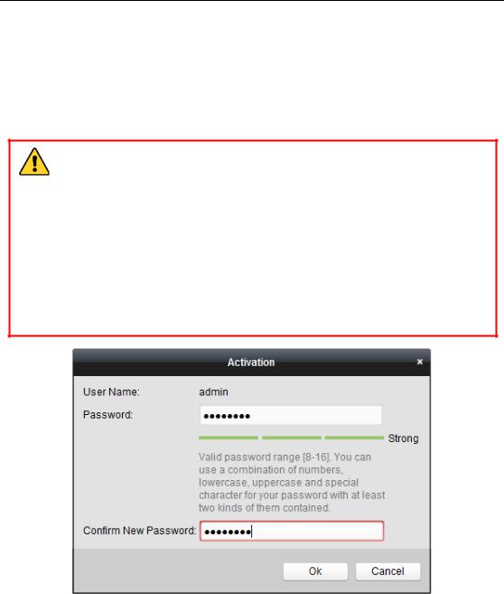
Figure 2-3 Activation Interface(Web)
3. Create a password and input the password into the password field.
STRONG PASSWORD RECOMMENDED– We highly recommend you create a strong password of your own choosing (using a minimum of 8 characters, including upper case letters, lower case letters, numbers, and special characters) in order to increase the security of your product. And we recommend you reset your password regularly, especially in the high security system, resetting the password monthly or weekly can better protect your product.
4.Confirm the password.
5.Click OK to save the password and enter the live view interface.
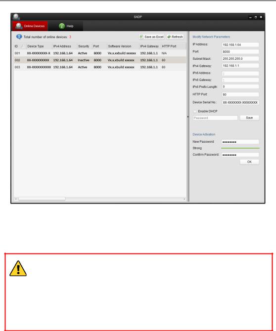
Activation via SADP Software
SADP software is used for detecting the online device, activating the camera, and resetting the password.
Get the SADP software from the supplied disk or the official website, and install the SADP according to the prompts. Follow the steps to activate the camera.
Steps:
1.Run the SADP software to search the online devices.
2.Check the device status from the device list, and select the inactive device.
13
User Manual of Thermal + Optical Bi-spectrum Network Bullet Camera
Figure 2-4 SADP Interface
3. Create a password and input the password in the password field, and confirm the
password.
STRONG PASSWORD RECOMMENDED– We highly recommend you create a strong password of your own choosing (using a minimum of 8 characters, including upper case letters, lower case letters, numbers, and special characters) in order to increase the security of your product. And we recommend you reset your password regularly, especially in the high security system, resetting the password monthly or weekly can better protect your product.
4. Click OK to save the password.
You can check whether the activation is completed on the popup window. If activation
failed, please make sure that the password meets the requirement and try again.
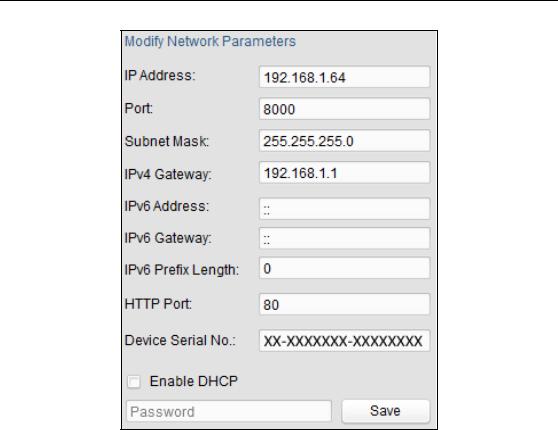
5. Change the device IP address to the same subnet with your computer by either
modifying the IP address manually or checking the checkbox of Enable DHCP.
14
User Manual of Thermal + Optical Bi-spectrum Network Bullet Camera
Figure 2-5 Modify the IP Address
6. Input the password and click the Save button to activate your IP address modification.
Activation via Client Software
The client software is versatile video management software for multiple kinds of devices.
Get the client software from the supplied disk or the official website, and install the software according to the prompts. Follow the steps to activate the camera.
Steps:
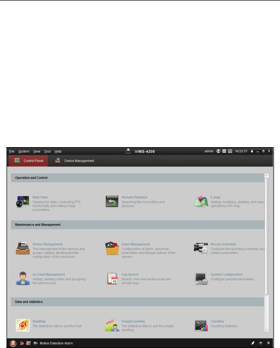
1. Run the client software and the control panel of the software pops up, as shown in the figure below.
15

User Manual of Thermal + Optical Bi-spectrum Network Bullet Camera
Figure 2-6 Control Panel
2. Click the Device Management icon to enter the Device Management interface, as shown in the figure below.
Figure 2-7 Device Management Interface
16
User Manual of Thermal + Optical Bi-spectrum Network Bullet Camera
3.Check the device status from the device list, and select an inactive device.
4.Click the Activate button to pop up the Activation interface.
5.Create a password and input the password in the password field, and confirm the password.
STRONG PASSWORD RECOMMENDED– We highly recommend you create a strong password of your own choosing (using a minimum of 8 characters, including upper case letters, lower case letters, numbers, and special characters) in order to increase the security of your product. We recommend you reset your password regularly, especially in the high security system, resetting the password monthly or weekly can better protect your product.
Figure 2-8 Activation Interface (Client Software)
6.Click OK button to start activation.
7.Click the Modify Netinfo button to pop up the Network Parameter Modification interface, as shown in the figure below.
17
User Manual of Thermal + Optical Bi-spectrum Network Bullet Camera
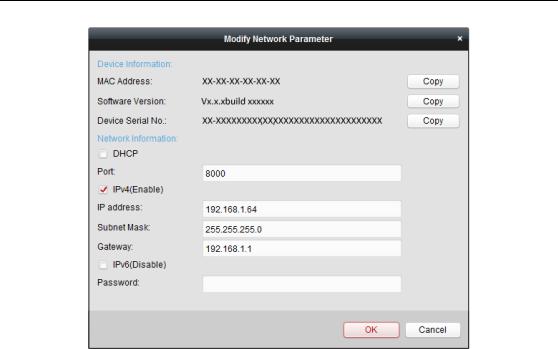
Figure 2-9 Modifying the Network Parameters
8.Change the device IP address to the same subnet with your computer by either modifying the IP address manually or checking the checkbox of Enable DHCP.
9.Input the password to activate your IP address modification.
2.2 Setting the Network Camera over the WAN
Purpose:
This section explains how to connect the network camera to the WAN with a static IP or a dynamic IP.
2.2.1 Static IP Connection
Before you start:
Please apply a static IP from an ISP (Internet Service Provider). With the static IP address, you can connect the network camera via a router or connect it to the WAN directly.
Connecting the network camera via a router
Steps:
1. Connect the network camera to the router.
18
User Manual of Thermal + Optical Bi-spectrum Network Bullet Camera
2.Assign a LAN IP address, the subnet mask and the gateway. Refer to Section 2.1.2 for detailed IP address configuration of the network camera.
3.Save the static IP in the router.
4.Set port mapping, e.g., 80, 8000, and 554 ports. The steps for port mapping vary according to the different routers. Please call the router manufacturer for assistance with port mapping.
Note: Refer to Appendix 2 for detailed information about port mapping.
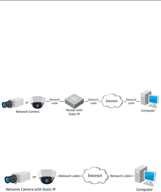
5.Visit the network camera through a web browser or the client software over the internet.
Figure 2-10 Accessing the Camera through Router with Static IP
Connecting the network camera with static IP directly
You can also save the static IP in the camera and directly connect it to the internet without using a router. Refer to Section 2.1.2 for detailed IP address configuration of the network camera.
Figure 2-11 Accessing the Camera with Static IP Directly
2.2.2 Dynamic IP Connection
Before you start:
Please apply a dynamic IP from an ISP. With the dynamic IP address, you can connect the network camera to a modem or a router.
Connecting the network camera via a router
Steps:
19

User Manual of Thermal + Optical Bi-spectrum Network Bullet Camera
1.Connect the network camera to the router.
2.In the camera, assign a LAN IP address, the subnet mask and the gateway. Refer to Section 2.1.2 for detailed IP address configuration of the network camera.
3.In the router, set the PPPoE user name, password and confirm the password.
4.Set port mapping. E.g. 80, 8000, and 554 ports. The steps for port mapping vary depending on different routers. Please call the router manufacturer for assistance
with port mapping.
Note: Refer to Appendix 2 for detailed information about port mapping.
5.Apply a domain name from a domain name provider.
6.Configure the DDNS settings in the setting interface of the router.
7.Visit the camera via the applied domain name.
Connecting the network camera via a modem
Purpose:
This camera supports the PPPoE auto dial-up function. The camera gets a public IP address by ADSL dial-up after the camera is connected to a modem. You need to configure the PPPoE parameters of the network camera. Refer to Section 6.3.3
Configuring PPPoE Settings for detailed configuration.
Figure 2-12 Accessing the Camera with Dynamic IP
Note: The obtained IP address is dynamically assigned via PPPoE, so the IP address always changes after rebooting the camera. To solve the inconvenience of the dynamic IP, you need to get a domain name from the DDNS provider (E.g. DynDns.com). Please follow the steps below for normal domain name resolution and private domain name resolution to solve the problem.
Normal Domain Name Resolution
20
User Manual of Thermal + Optical Bi-spectrum Network Bullet Camera
Figure 2-13 Normal Domain Name Resolution
Steps:
1.Apply a domain name from a domain name provider.
2.Configure the DDNS settings in the DDNS Settings interface of the network camera. Refer to Section 6.3.4 Configuring DDNS Settings for detailed configuration.
3.Visit the camera via the applied domain name.
Private Domain Name Resolution
Figure 2-14 Private Domain Name Resolution
Steps:
1.Install and run the IP Server software in a computer with a static IP.
2.Access the network camera through the LAN with a web browser or the client software.
3.Enable DDNS and select IP Server as the protocol type. Refer to Section 6.3.4
Configuring DDNS Settings for detailed configuration.
21

User Manual of Thermal + Optical Bi-spectrum Network Bullet Camera
Chapter 3 Access to the Network Camera
3.1 Accessing by Web Browsers
Steps:
1.Open the web browser.
2.In the browser address bar, input the IP address of the network camera, and press the Enter key to enter the login interface.
3.Activate the network camera for the first time using, refer to the section 2.1.2 for details.
Note:
The default IP address is 192.168.1.64.
If the camera is not activated, please activate the camera first according to Chapter 3.1 or Chapter 3.2.
4.Select English as the interface language on the top-right of login interface.
5.Input the user name and password and click .
.
The admin user should configure the device accounts and user/operator permissions properly. Delete the unnecessary accounts and user/operator permissions.
Note:
The device IP address gets locked if the admin user performs 7 failed password attempts (5 attempts for the user/operator).
Figure 3-1 Login Interface
22
User Manual of Thermal + Optical Bi-spectrum Network Bullet Camera
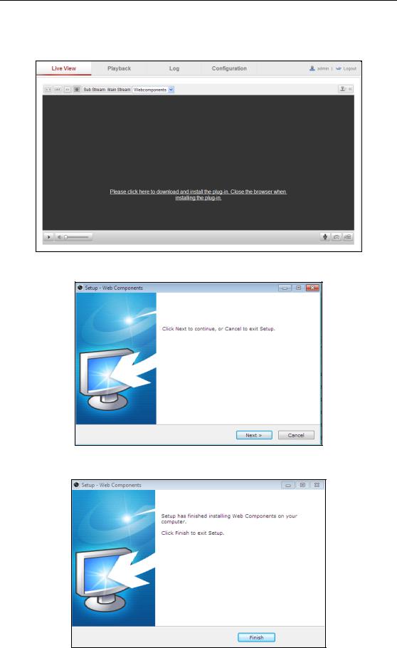
6.Install the plug-in before viewing the live video and operating the camera. Please follow the installation prompts to install the plug-in.
Figure 3-2 Download and Install Plug-in
Figure 3-3 Install Plug-in (1)
Figure 3-4 Install Plug-in (2)
23
User Manual of Thermal + Optical Bi-spectrum Network Bullet Camera
Note: You may have to close the web browser to install the plug-in. Please reopen the web browser and log in again after installing the plug-in.
3.2 Accessing by Client Software
The product CD contains the iVMS-4200 client software. You can view the live video and manage the camera with the software.
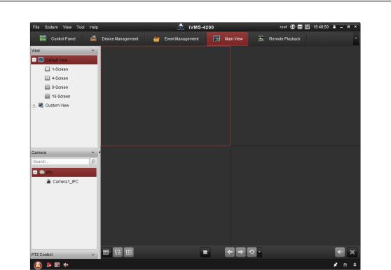
Follow the installation prompts to install the software. The control panel and live view interface of iVMS-4200 client software are shown as below.
Figure 3-5 iVMS-4200 Control Panel
24
User Manual of Thermal + Optical Bi-spectrum Network Bullet Camera
Figure 3-6 iVMS-4200 Main View
Note: For detailed information about the software, please refer to the user manual of
the iVMS-4200.
25
User Manual of Thermal + Optical Bi-spectrum Network Bullet Camera
Chapter 4Live View
4.1 Live View Page
Purpose:
The live view page allows you to view the real-time video, capture images, realize PTZ control, set/call presets and configure video parameters.
Log in the network camera to enter the live view page, or you can click Live View on the menu bar of the main page to enter the live view page.
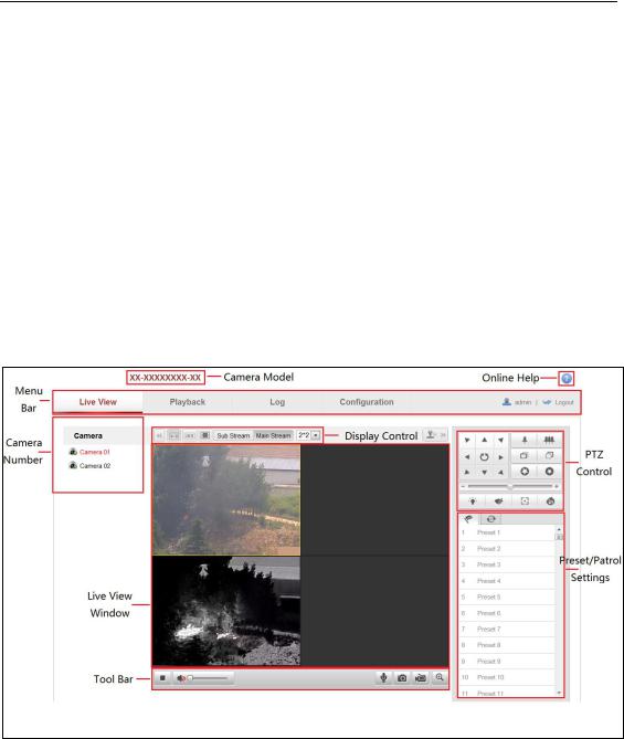
Descriptions of the live view page:
Figure 4-1 Live View Page
Camera Model:
It lists the camera model you are connecting to.
Online Help:
Click  to get the online help, which will guide you through the basic operations for each function.
Menu Bar:
Click each tab to enter Live View, Playback, Log and Configuration page
26

User Manual of Thermal + Optical Bi-spectrum Network Bullet Camera
respectively.
Camera Number:
For camera models which have more than one camera channels, you can control the display layout. Click a display screen to select it. Then double-click the desired camera channel to show its live view on the screen.
Display Control:
Click each button to adjust the layout and the stream type of the live view. You can click the drop-down to select the layout for display. For IE (internet explorer) user, webcomponents and quick time are selectable. And for Non-IE user, webcomponents, quick time, VLC or MJPEG is selectable if they are supported by the web browser.
Live View Window:
Display the live video.
Toolbar:
Operations on the live view page, e.g., start/stop live view, capture, record, start/stop two-way audio, etc.
PTZ Control:
Panning, tilting and zooming actions of the camera and the light and wiper control. (only available for cameras supporting PTZ function)
Preset/Patrol Settings:
Set/call/delete the presets or patrols for PTZ cameras.
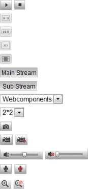
4.2 Starting Live View
In the live view window as shown in Figure 4-2, click  on the toolbar to start the live view of the camera.
Figure 4-2 Live View Toolbar
27
|
User Manual of Thermal + Optical Bi-spectrum Network Bullet Camera |
|
|
|
|
|
|
|
Table 4-1 Descriptions of the Display Control Bar and the Toolbar |
|
|
|
|
|
|
|
Icon |
Description |
|
|
/ |
Start/Stop live view. |
|
|
|
|
|
|
|
The window size is 4:3. |
|
|
|
|
|
|
|
The window size is 16:9. |
|
|
|
|
|
|
|
The original widow size. |
|
|
|
|
|
|
|
Self-adaptive window size. |
|
|
|
|
|
|
|
Live view with the main stream. |
|
|
|
|
|
|
|
Live view with the sub stream. |
|
|
|
|
|
|
|
Click to select the third-party plug-in. |
|
|
|
Window division |
|
|
|
|
|
|
|
Manually capture the picture. |
|
|
|
|
|
|
/ |
Manually start/stop recording. |
|
|
|
|
|
|
/ |
Audio on and adjust volume /Mute. |
|
|
|
|
|
|
/ |
Start/stop two-way audio. |
|
|
|
|
|
|
/ |
Enable/disable e-PTZ function. |
|
|
|
|
|
4.3 Recording and Capturing Pictures Manually
In the live view interface, click  on the toolbar to capture the live pictures or
click  to record the live view. The saving paths of the captured pictures and clips can be set on the Configuration > Local Configuration page. To configure remote scheduled recording, please refer to Section 6.3.
Note: The captured image will be saved as JPEG file or BMP file in your computer.
4.4 Operating PTZ Control
Purpose:
In the live view interface, you can use the PTZ control buttons to realize pan/tilt/zoom control of the camera.
Note: To realize PTZ control, the camera connected to the network must support the
28
User Manual of Thermal + Optical Bi-spectrum Network Bullet Camera
PTZ function or a pan/tilt unit has been installed to the camera. Please properly set the PTZ parameters on RS-485 settings page, referring to Section 9.9 RS-485 Settings.
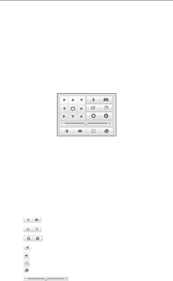
4.4.1 PTZ Control Panel
On the live view page:
Click  to show the PTZ control panel or click
  to hide it. Click the direction buttons to control the pan/tilt movements.
Click the zoom/iris/focus buttons to realize lens control.
Figure 4-3 PTZ Control Panel
Notes:
There are 8 direction arrows ( ,
,  ,
,  ,
,  ,
,  ,
,  ,
,  ,
,  ) in the live view window when you click and drag the mouse in the relative positions.
For the cameras which support lens movements only, the direction buttons are invalid.
|
Table 4-2 Descriptions of PTZ Control Panel |
|
|
|
|
Icon |
|
Description |
|
|
Zoom in/out |
|
|
|
|
|
Focus near/far |
|
|
|
|
|
Iris +/- |
|
|
|
|
|
Light on/off |
|
|
|
|
|
Wiper on/off |
|
|
|
|
|
Auxiliary focus |
|
|
|
|
|
Initialize lens |
|
|
Adjust speed of pan/tilt movements |
|
|
|
29
User Manual of Thermal + Optical Bi-spectrum Network Bullet Camera
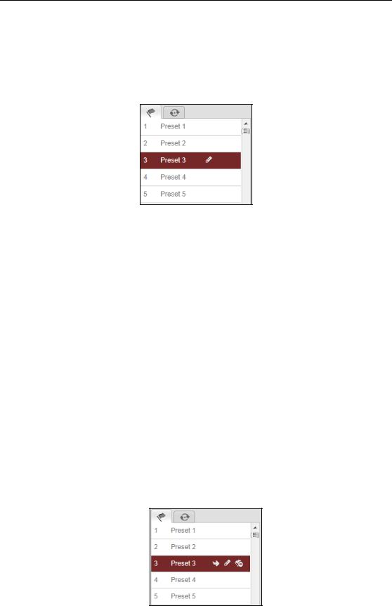
4.4.2Setting/Calling a Preset
Setting a Preset:
1. In the PTZ control panel, select a preset number from the preset list.
Figure 4-4 Setting a Preset
2.Use the PTZ control buttons to move the lens to the desired position.
•Pan the camera to the right or left.
•Tilt the camera up or down.
•Zoom in or out.
•Refocus the lens.
3.Click  to finish the setting of the current preset.
4.You can click  to delete the preset.
Note: Up to 256 presets can be configured for the Thermal Network Camera.
Calling a Preset:
This feature enables the camera to point to a specified preset scene manually or when an event takes place.
Figure 4-5 Calling a Preset
For the defined preset, you can call it at any time to the desired preset scene.
30
 Loading...