


Hikvision DS-9508NI-S-2TB, DS-9508NI-S-4TB, DS-9508NI-S, DS-9516NI-S-1TB, DS-9516NI-S-2TB User Manual
...DS-9500NI-S Series NVR
USER MANUAL
Version 1.2.0
Hikvision® Network Digital Video Recorder User’s Manual
This manual, as well as the software described in it, is furnished under license and may be used or copied only in accordance with the terms of such license. The content of this manual is furnished for informational use only, is subject to change without notice, and should not be construed as a commitment by Hikvision Digital Technology Co., Ltd. (Hikvision). Hikvision assumes no responsibility or liability for any errors or inaccuracies that may appear in the book.
Except as permitted by such license, no part of this publication may be reproduced, stored in a retrieval system, or transmitted, in any form or by any means, electronic, mechanical, recording, or otherwise, without the prior written permission of Hikvision.
HIKVISION MAKES NO WARRANTIES, EXPRESS OR IMPLIED, INCLUDING WITHOUT LIMITATION THE IMPLIED WARRANTIES OF MERCHANTABILITY AND FITNESS FOR A PARTICULAR PURPOSE, REGARDING THE HIKVISION SOFTWARE. HIKVISION DOES NOT WARRANT, GUARANTEE, OR MAKE ANY REPRESENTATIONS REGARDING THE USE OR THE RESULTS OF THE USE OF THE HIKVISION SOFTWARE IN TERMS OF ITS CORRECTNESS, ACCURACY, RELIABILITY, CURRENTNESS, OR OTHERWISE. THE ENTIRE RISK AS TO THE RESULTS AND PERFORMANCE OF THE HIKVISION SOFTWARE IS ASSUMED BY YOU. THE EXCLUSION OF IMPLIED WARRANTIES IS NOT PERMITTED BY SOME STATES. THE ABOVE EXCLUSION MAY NOT APPLY TO YOU.
IN NO EVENT WILL HIKVISION, ITS DIRECTORS, OFFICERS, EMPLOYEES, OR AGENTS BE LIABLE TO YOU FOR ANY CONSEQUENTIAL, INCIDENTAL, OR INDIRECT DAMAGES (INCLUDING DAMAGES FOR LOSS OF BUSINESS PROFITS, BUSINESS INTERRUPTION, LOSS OF BUSINESS INFORMATION, AND THE LIKE) ARISING OUT OF THE USE OR INABILITY TO USE THE HIKVISION SOFTWARE EVEN IF HIKVISION HAS BEEN ADVISED OF THE POSSIBILITY OF SUCH DAMAGES. BECAUSE SOME STATES DO NOT ALLOW THE EXCLUSION OR LIMITATION OF LIABILITY FOR CONSEQUENTIAL OR INCIDENTAL DAMAGES, THE ABOVE LIMITATIONS MAY NOT APPLY TO YOU.
1
Preventive and Cautionary Tips
Before connecting and operating your NVR, please be advised of the following tips:
•Ensure unit is installed in a well-ventilated, dust-free environment.
•Unit is designed for indoor use only.
•Keep all liquids away from the NVR.
•Ensure environmental conditions meet factory specifications.
•Ensure unit is properly secured to a rack or shelf. Major shocks or jolts to the unit as a result of dropping it may cause damage to the sensitive electronics within the unit.
•Use the NVR in conjunction with an UPS if possible.
•Power down the unit before connecting and disconnecting accessories and peripherals.
•A factory recommended HDD should be used for this device.
2
TABLE OF CONTENTS
C H A P T E R 1 ...................................................................................................................................... |
5 |
|
Introduction............................................................................................................................................. |
5 |
|
1.1 |
Front Panel Introduction ........................................................................................................... |
6 |
1.2 |
Starting and Shutting Down Your NVR .................................................................................... |
8 |
C H A P T E R 2 .................................................................................................................................... |
10 |
|
Network Parameters Configuration....................................................................................................... |
10 |
|
2.1 |
Hyper Terminal Setup ............................................................................................................. |
11 |
2.2 |
Network Configuration by Hyper Terminal ............................................................................ |
13 |
C H A P T E R 3 .................................................................................................................................... |
15 |
|
ActiveX Control Installation ................................................................................................................. |
15 |
|
C H A P T E R 4 .................................................................................................................................... |
17 |
|
User Login and Exit .............................................................................................................................. |
17 |
|
C H A P T E R 5 .................................................................................................................................... |
19 |
|
Preview |
................................................................................................................................................. |
19 |
5.1 |
Preview ................................................................................................................................... |
20 |
|
5.1.1 Windows Division ........................................................................................................ |
20 |
|
5.1.2 Preview......................................................................................................................... |
21 |
|
5.1.3 Preview Control ........................................................................................................... |
21 |
|
5.1.4 Stop Preview ................................................................................................................ |
22 |
5.2 |
Recording and Capturing Image ............................................................................................. |
22 |
|
5.2.1 Recording ..................................................................................................................... |
22 |
|
5.2.2 Capturing Image........................................................................................................... |
23 |
5.3 |
Video Parameters Setting ........................................................................................................ |
23 |
C H A P T E R 6 .................................................................................................................................... |
24 |
|
PTZ Control .......................................................................................................................................... |
24 |
|
C H A P T E R 7 .................................................................................................................................... |
26 |
|
Playback................................................................................................................................................ |
26 |
|
7.1 |
Playback Query ....................................................................................................................... |
27 |
7.2 |
Play Recording File................................................................................................................. |
28 |
7.3 |
Capturing Image and Download ............................................................................................. |
29 |
7.4 |
Remote Backup ....................................................................................................................... |
30 |
C H A P T E R 8 .................................................................................................................................... |
31 |
|
Log Search ............................................................................................................................................ |
31 |
|
C H A P T E R 9 .................................................................................................................................... |
33 |
|
Configuration ........................................................................................................................................ |
33 |
|
9.1 |
Local Configuration ................................................................................................................ |
34 |
9.2 |
IP Camera Configuration ........................................................................................................ |
34 |
|
9.2.1 Quick Add of IP camera ............................................................................................... |
35 |
|
9.2.2 Single Add of IP camera............................................................................................... |
36 |
9.3 |
Recording Settings .................................................................................................................. |
38 |
|
9.3.1 Video Parameters ......................................................................................................... |
39 |
|
9.3.2 Schedule Recording ..................................................................................................... |
39 |
|
9.3.3 Motion Detection Recording........................................................................................ |
41 |
|
9.3.4 Alarm Recording .......................................................................................................... |
43 |
|
9.3.5 Other Recording Modes ............................................................................................... |
45 |
9.4 Alarm Settings......................................................................................................................... |
45 |
|
|
9.4.1 Motion Detection Alarm .............................................................................................. |
45 |
|
9.4.2 Signal Level Alarm ...................................................................................................... |
46 |
|
9.4.3 Video Loss.................................................................................................................... |
47 |
|
9.4.4 Video Tampering .......................................................................................................... |
48 |
|
3 |
|
9.4.5 Exceptions.................................................................................................................... |
49 |
9.5 Network Configuration ........................................................................................................... |
50 |
9.5.1 Basic Configuration ..................................................................................................... |
50 |
9.5.2 PPPoE Settings............................................................................................................. |
51 |
9.5.3 DDNS Settings ............................................................................................................. |
51 |
9.5.4 NTP Settings ................................................................................................................ |
51 |
9.5.5 Net Disk Settings.......................................................................................................... |
52 |
9.5.6 E-Mail Settings ............................................................................................................ |
52 |
9.6 Channel Configuration ............................................................................................................ |
53 |
9.6.1 Channel Display Settings ............................................................................................. |
53 |
9.6.2 Video Mask .................................................................................................................. |
53 |
9.7 Account Management ............................................................................................................. |
54 |
9.8 Remote Upgrade ..................................................................................................................... |
55 |
9.9 HDD Settings .......................................................................................................................... |
56 |
C H A P T E R 10 .................................................................................................................................. |
58 |
Appendix............................................................................................................................................... |
58 |
Glossary ........................................................................................................................................ |
59 |
FAQ............................................................................................................................................... |
60 |
List of Compatible IP Cameras ..................................................................................................... |
61 |
List of Hikvision IP Cameras Supported by DS-9500NI-S NVR ......................................... |
61 |
List of Third-party IP Cameras Supported by DS-9500NI-S NVR....................................... |
62 |
4
C H A P T E R 1
Introduction
5
1.1 Front Panel Introduction
DS-9504NI-S Front Panel:
|
No. |
|
|
|
Name |
|
|
Description |
|
|||
|
|
|
|
|
|
|
||||||
|
|
|
|
|
|
|
|
Power |
|
|
Turning red indicates power supply but without system running, turning blue |
|
|
|
|
|
|
|
|
|
|
|
|||
|
|
|
|
|
|
|
|
|
|
indicates power supply and system running. |
||
|
|
|
|
|
|
|
|
|
|
|
||
|
|
|
|
|
|
|
|
Alarm |
|
|
Alarm indicator turns red when a sensor alarm is detected. |
|
|
1 |
|
|
Status |
|
|
|
TX/RX |
|
|
TX/RX indictor blinks blue when network connection is functioning properly. |
|
|
|
|
|
|
|
|
|
|||||
|
|
|
|
LED |
|
|
|
|
|
|||
|
|
|
|
|
|
|
HDD |
|
|
HDD indicator blinks red when data is being read from or written to HDD. |
||
|
|
|
|
|
|
|
|
|
||||
|
|
|
|
Indicators |
|
|
|
|
||||
|
|
|
|
|
|
|
||||||
|
|
|
|
|
|
|
|
|
|
|
||
|
|
|
|
|
|
|
|
Ready |
|
|
Ready indicator turns blue when NVR is functioning properly. |
|
|
|
|
|
|
|
|
|
|
|
|||
|
|
|
|
|
|
|
|
|
|
|
|
|
|
|
|
|
|
|
|
|
|
|
|
|
|
|
|
|
|
|
|
|
|
Backup |
|
|
Backup indicator blinks blue when data is being backup. |
|
|
2 |
|
|
Power Button |
|
|
Powers NVR on/off. |
|||||
|
|
|
|
|
||||||||
|
|
|
|
|
|
|
|
|
|
|
|
|
|
3 |
|
|
USB Ports |
|
|
Universal Serial Bus (USB) ports for additional devices such as USB mouse and |
|||||
|
|
|
|
|
||||||||
|
|
|
|
|
|
|
|
|
|
USB Hard Disk Drive (HDD). |
||
|
|
|
|
|
|
|
|
|
|
|
||
|
4 |
|
|
Channel Status |
|
|
Blue indicates recording, red indicates network connection, purple indicates |
|||||
|
|
|
|
|
||||||||
|
|
|
Indicators |
|
|
|||||||
|
|
|
|
|
recording & network connection. |
|||||||
|
|
|
|
|
|
|||||||
|
|
|
|
|
|
|
|
|
|
|
||
|
|
|
|
|
|
|
|
|
||||
|
5 |
|
|
Backup Button |
|
|
Backup video files. |
|||||
|
|
|
|
|
||||||||
|
|
|
|
|
|
|
|
|
|
|||
|
|
|
|
|
|
|
|
|
|
|
|
|
6
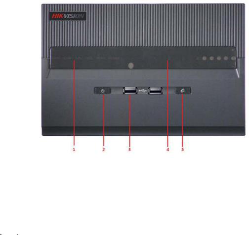
DS-9508NI-S Front Panel:
|
No. |
|
|
|
|
Name |
|
|
Description |
|
||
|
|
|
|
|
|
|
|
|||||
|
|
|
|
|
|
|
|
Power |
|
|
Turning red indicates power supply but without system running, turning blue |
|
|
|
|
|
|
|
|
|
|
|
|||
|
|
|
|
Status |
|
|
|
|
|
indicates power supply and system running. |
||
|
|
|
|
|
|
|
|
|
|
|||
|
|
|
|
|
|
|
|
|
|
|
||
|
|
|
|
|
|
|
Alarm |
|
|
Alarm indicator turns red when a sensor alarm is detected. |
||
|
|
|
|
|
|
|
|
|
||||
|
1 |
|
|
LED |
|
|
|
|
|
|
|
|
|
|
|
|
|
|
TX/RX |
|
|
TX/RX indictor blinks blue when network connection is functioning properly. |
|||
|
|
|
|
|
|
|
|
|||||
|
|
|
|
Indicators |
|
|
|
|
||||
|
|
|
|
|
|
HDD |
|
|
HDD indicator blinks red when data is being read from or written to HDD. |
|||
|
|
|
|
|
|
|
|
|||||
|
|
|
|
|
|
|
|
|
|
|||
|
|
|
|
|
|
|
||||||
|
|
|
|
|
|
|
|
Ready |
|
|
Ready indicator turns blue when NVR is functioning properly. |
|
|
|
|
|
|
|
|
|
Backup |
|
|
Backup indicator blinks blue when data is being backup. |
|
|
2 |
|
|
|
USB Ports |
|
|
Universal Serial Bus (USB) ports for additional devices such as USB mouse and |
||||
|
|
|
|
|
|
|||||||
|
|
|
|
|
|
|
|
|
|
USB Hard Disk Drive (HDD). |
||
|
|
|
|
|
|
|
|
|
|
|
||
|
3 |
|
|
|
Power Button |
|
|
Powers NVR on/off. |
||||
|
|
|
|
|
|
|||||||
|
|
|
|
|
|
|
|
|
|
|
|
|
|
4 |
|
|
Backup Button |
|
|
Backup video files. |
|||||
|
|
|
|
|
|
|
|
|
|
|
|
|
|
|
|
|
|
|
|
|
|||||
|
5 |
|
|
Channel Status Indicators |
|
|
Blue indicates recording, red indicates network connection, purple indicates |
|||||
|
|
|
|
|
||||||||
|
|
|
|
|
|
|
|
|
|
recording & network connection. |
||
|
|
|
|
|
|
|
|
|
|
|
||
7

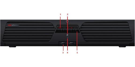
DS-9516NI-S Front Panel:
|
No. |
|
|
Name |
|
|
|
Description |
|
|||
|
|
|
|
|
|
|
||||||
|
|
|
|
|
|
|||||||
|
|
|
|
|
|
|
|
|
|
|
||
|
|
|
|
|
|
|
|
|
|
|
|
|
|
|
|
|
|
|
|
|
Power |
|
|
Turning red indicates power supply but without system running, turning blue |
|
|
|
|
|
|
|
|
|
|
|
|||
|
|
|
|
Status |
|
|
|
|
|
indicates power supply and system running. |
||
|
|
|
|
|
|
|
|
|
|
|||
|
|
|
|
|
|
|
Alarm |
|
|
Alarm indicator turns red when a sensor alarm is detected. |
||
|
|
|
|
|
|
|
|
|
||||
|
|
|
|
LED |
|
|
|
|
|
|||
|
|
|
|
|
|
|
|
|
|
|
|
|
|
|
|
|
|
|
|
|
|
|
|
|
|
|
1 |
|
|
Indicators |
|
|
TX/RX |
|
|
TX/RX indictor blinks blue when network connection is functioning properly. |
||
|
|
|
|
|
|
|
||||||
|
|
|
|
|
|
|
|
|
|
|
|
|
|
|
|
|
|
|
|
|
|
|
|
|
|
|
|
|
|
|
|
|
|
HDD |
|
|
HDD indicator blinks red when data is being read from or written to HDD. |
|
|
|
|
|
|
|
|
|
|
|
|||
|
|
|
|
|
|
|
|
|
|
|
|
|
|
|
|
|
|
|
|
|
|
|
|
|
|
|
|
|
|
|
|
|
|
Ready |
|
|
Ready indicator turns blue when NVR is functioning properly. |
|
|
|
|
|
|
|
|
|
|
|
|
||
|
|
|
|
|
|
|
|
|
|
|
||
|
|
|
|
|
|
|
Backup |
|
|
Backup indicator blinks blue when data is being backup. |
||
|
|
|
|
|
|
|
|
|
|
|
|
|
|
2 |
|
|
Backup Button |
|
|
Backup video files. |
|||||
|
|
|
|
|
||||||||
|
|
|
|
|
|
|
|
|
|
|||
|
|
|
|
|
|
|
|
|
||||
|
3 |
|
|
USB Ports |
|
|
|
Universal Serial Bus (USB) ports for additional devices such as USB mouse and |
||||
|
|
|
|
|
|
|||||||
|
|
|
|
|
|
|
|
|
|
USB Hard Disk Drive (HDD). |
||
|
|
|
|
|
|
|
|
|
|
|
||
|
4 |
|
|
Power Button |
|
|
Powers NVR on/off. |
|||||
|
|
|
|
|
||||||||
|
|
|
|
|
|
|
|
|
|
|||
|
|
|
|
|
|
|
|
|||||
|
|
|
|
Channel Status |
|
|
Blue indicates recording, red indicates network connection, purple indicates |
|||||
|
|
|
|
|
|
|||||||
|
5 |
|
|
|
|
|||||||
|
|
|
Indicators |
|
|
recording & network connection. |
||||||
|
|
|
|
|
|
|||||||
1.2 Starting and Shutting Down Your NVR
Power On
If the power LED indicator on the front panel is off, please plug the power supply into an electrical outlet, the LED should turn red, indicating the unit is receiving power.
When the LED is red, please press the Power button on the front panel. The Power indicator will turn blue. The unit will begin to start.
Note: DS-9500NI-S series NVR do not have local output, when Ready indicator turns blue, that means the unit is power on and ready to be configured.
8
Power Off
Standard Shutdown
Press and hold the POWER button for 3 seconds; the device will enter power off process, when power indicator turns red, turn off the power switch on the back panel.
Other Methods of Shutdown
Shutdown with Power Switch
Please try to avoid shutting down the unit by turn off the power switch on the back panel (especially during recording).
Shutdown by Unplug Power Supply
Please try to avoid shutting down the unit by unplug power supply (especially during recording).
Note: It is highly recommended that an Uninterruptible Power Supply (UPS) be used in conjunction with the unit.
9
C H A P T E R 2
Network Parameters Configuration
10
DS-9500NI-S Series NVR are mainly for IPC, DVS network video storage and playback. Network configurations are needed before operating, including: IP address, subnet mask, gateway and port.
Note: The factory default username is admin, password is 12345.
The factory default IP address of DS-9500NI-S series is 192.168.0.1.
2.1 Hyper Terminal Setup
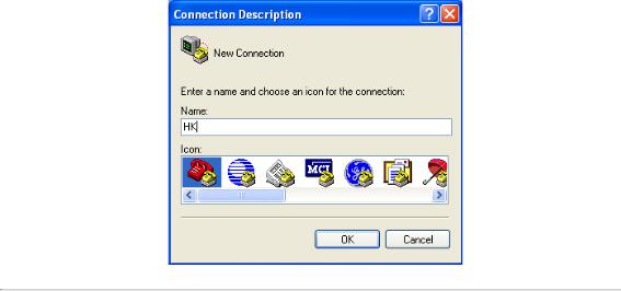
The common method is to connect NVR and PC with serial line, run Hyper Terminal and modify parameters with serial command. Please connect the RS-232 port of NVR with the COM port of PC directly, power on the NVR and PC and follow the steps:
Step 1: Enter Hyper Terminal.
Click “Start”-> “Programs” -> “Accessories” -> “Communications” -> “Hyper Terminal” in Windows system, and the dialogue box below will appears as Figure 2.1.1.
Figure 2.1.1
Step 2: Name the connection and define the icon.
Input a name (e.g. HK), select an icon, and press “OK” to enter “Connect To” dialogue box.
Step 3: Select the communication port.
Select “COM1” in “Connect To” inter face (Please select the COM port according to the reality, in case PC has more than 1 COM.) Press “OK” to enter “Properties” dialogue box.
11
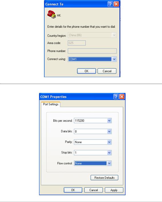
Figure 2.1.2
Step 4: Serial port setup.
Set port parameters in “COM1 Properties” dialogue box as follow: (Fig 2.1.3)
Figure 2.1.3
The parameters should be:
Bits per second: 115200
Data bits: 8
Parity: None
Stop bits: 1
Flow control: None
Press “Apply” and “OK” after the setup. Press “Enter” under Hyper Terminal interface. When “[root@dvrdvs/]#” appears, the connection is established.
12

Figure 2.1.4
Step5: Disconnect and save connection.
According to the tips, disconnect and save “HK” for the next time. After saving, there will be a new “Hyper Terminal” item established in the program group “Start”-> “Accessories”->“Communications”->“Hyper Terminal”. “Connection” names of all Hyper Terminal are included. You can see an icon named as “HK” here.
2.2 Network Configuration by Hyper Terminal
Enter Hyper Terminal
Click “Start”->“Programs”->“Accessories”->“Communications”->“Hyper Terminal”->“HK”, then the Hyper Terminal interface will appear as figure below. Type “Enter”, and the prompt “[root@dvrdvs/]#” will appear which means connection between RS232 interface of PC and RS232 interface of NVR is established successfully by Hyper Terminal. The following operation commands are to accomplish the parameters setup in the prompt.
13

Figure 2.2.1
|
Commands |
|
|
Utilities |
|
|
helpm |
|
|
Console help command is used to print common commands, show as Figure 2.2.1. |
|
|
getIp |
|
|
Show the current IP address of NVR. Command format: getIp “Enter”. |
|
|
setIp |
|
|
Setup NVR IP address. Command format: setIp IP: mask |
|
|
|
|
e.g. setIp 192..168.1.11:255.255.255.0 |
|
|
|
|
|
|
|
|
|
getPort |
|
|
Show the current port of NVR. Command format: getPort “Enter”. |
|
|
setPort |
|
|
Setup NVR port. Command format: setPort Port |
|
|
|
|
e.g. setPort 9000 |
|
|
|
|
|
|
|
|
|
getGateway |
|
|
Show current NVR gateway address. Command format: getGateway “Enter”. |
|
|
setGateway |
|
|
Setup NVR gateway. Command format: setGateway Gateway |
|
|
|
|
e.g. setGateway 192.168.1.1 |
|
|
|
|
|
|
|
14
C H A P T E R 3
ActiveX Control Installation
15
DS-9500NI-S series NVR can be accessed and configured by web server. Open IE browser, input the IP address of DS-9500NI-S and then click Enter. The system will remind you to install the ActiveX control. After the installation, you can configure and manage the NVR remotely.
The ActiveX control has English and Chinese to selections. It can be used under 1024*768, 1152*864, 1280*1024 display resolutions.
Note: Please use IE 6.0 or IE 7.0 as browser, and upgrade OS to the latest version.
16
C H A P T E R 4
User Login and Exit
17

Open IE browser, input the IP address of NVR, the web server will select the language automatically according to the system language and maximize the IE browser.
Figure 4.1
On the top right corner, language is selectable between Chinese and English.
Input the correct user name, password and port, click “Login” to enter preview interface, or it will pop up an error box. The default user name is admin, password is 12345, and port is 8000.
After login, click “Exit” to log off and return to the login interface.
18
C H A P T E R 5
Preview
19
 Loading...