

Hikvision DS-7308HQHI-SH-12TB, DS-7308HQHI-SH-16TB, DS-7308HQHI-SH-1TB, DS-7308HQHI-SH-2TB, DS-7308HQHI-SH-3TB User Manual
...
Digital Video Recorder
User Manual
UD.6L0202D1962A01

User Manual of Digital Video Recorder
User Manual
COPYRIGHT ©2015 Hangzhou Hikvision Digital Technology Co., Ltd.
ALL RIGHTS RESERVED.
Any and all information, including, among others, wordings, pictures, graphs are the properties of Hangzhou
Hikvision Digital Technology Co., Ltd. or its subsidiaries (hereinafter referred to be “Hikvision”). This user
manual (hereinafter referred to be “the Manual”) cannot be reproduced, changed, translated, or distributed,
partially or wholly, by any means, without the prior written permission of Hikvision. Unless otherwise
stipulated, Hikvision does not make any warranties, guarantees or representations, express or implied, regarding
to the Manual.
About this Manual
This Manual is applicable to TVI series DVR.
The Manual includes instructions for using and managing the product. Pictures, charts, images and all other
information hereinafter are for description and explanation only. The information contained in the Manual is
subject to change, without notice, due to firmware updates or other reasons. Please find the latest version in the
company website (http://overseas.hikvision.com/en/).
Please use this user manual under the guidance of professionals.
Trademarks Acknowledgement
and other Hikvision’s trademarks and logos are the properties of Hikvision in various
jurisdictions. Other trademarks and logos mentioned below are the properties of their respective owners.
Legal Disclaimer
TO THE MAXIMUM EXTENT PERMITTED BY APPLICABLE LAW, THE PRODUCT DESCRIBED,
WITH ITS HARDWARE, SOFTWARE AND FIRMWARE, IS PROVIDED “AS IS”, WITH ALL FAULTS
AND ERRORS, AND HIKVISION MAKES NO WARRANTIES, EXPRESS OR IMPLIED, INCLUDING
WITHOUT LIMITATION, MERCHANTABILITY, SATISFACTORY QUALITY, FITNESS FOR A
PARTICULAR PURPOSE, AND NON-INFRINGEMENT OF THIRD PARTY. IN NO EVENT WILL
HIKVISION, ITS DIRECTORS, OFFICERS, EMPLOYEES, OR AGENTS BE LIABLE TO YOU FOR ANY
SPECIAL, CONSEQUENTIAL, INCIDENTAL, OR INDIRECT DAMAGES, INCLUDING, AMONG
OTHERS, DAMAGES FOR LOSS OF BUSINESS PROFITS, BUSINESS INTERRUPTION, OR LOSS OF
DATA OR DOCUMENTATION, IN CONNECTION WITH THE USE OF THIS PRODUCT, EVEN IF
HIKVISION HAS BEEN ADVISED OF THE POSSIBILITY OF SUCH DAMAGES.
REGARDING TO THE PRODUCT WITH INTERNET ACCESS, THE USE OF PRODUCT SHALL BE
WHOLLY AT YOUR OWN RISKS. HIKVISION SHALL NOT TAKE ANY RESPONSIBILITES FOR
ABNORMAL OPERATION, PRIVACY LEAKAGE OR OTHER DAMAGES RESULTING FROM CYBER
ATTACK, HACKER ATTACK, VIRUS INSPECTION, OR OTHER INTERNET SECURITY RISKS;
HOWEVER, HIKVISION WILL PROVIDE TIMELY TECHNICAL SUPPORT IF REQUIRED.
SURVEILLANCE LAWS VARY BY JURISDICTION. PLEASE CHECK ALL RELEVANT LAWS IN
YOUR JURISDICTION BEFORE USING THIS PRODUCT IN ORDER TO ENSURE THAT YOUR USE
CONFORMS THE APPLICABLE LAW. HIKVISION SHALL NOT BE LIABLE IN THE EVENT THAT
THIS PRODUCT IS USED WITH ILLEGITIMATE PURPOSES.
IN THE EVENT OF ANY CONFLICTS BETWEEN THIS MANUAL AND THE APPLICABLE LAW, THE
LATER PREVAILS.
1

User Manual of Digital Video Recorder
Regulatory Information
FCC Information
FCC compliance: This equipment has been tested and found to comply with the limits for a Class A digital
device, pursuant to part 15 of the FCC Rules. These limits are designed to provide reasonable protection against
harmful interference when the equipment is operated in a commercial environment. This equipment generates,
uses, and can radiate radio frequency energy and, if not installed and used in accordance with the instruction
manual, may cause harmful interference to radio communications. Operation of this equipment in a residential
area is likely to cause harmful interference in which case the user will be required to correct the interference at
his own expense.
FCC Conditions
This device complies with part 15 of the FCC Rules. Operation is subject to the following two conditions:
1. This device may not cause harmful interference.
2. This device must accept any interference received, including interference that may cause undesired operation.
EU Conformity Statement
This product and - if applicable - the supplied accessories too are marked with "CE" and comply
therefore with the applicable harmonized European standards listed under the EMC Directive
2004/108/EC, the RoHS Directive 2011/65/EU.
2012/19/EU (WEEE directive): Products marked with this symbol cannot be disposed of as
unsorted municipal waste in the European Union. For proper recycling, return this product to your
local supplier upon the purchase of equivalent new equipment, or dispose of it at designated
collection points. For more information see: www.recyclethis.info
2006/66/EC (battery directive): This product contains a battery that cannot be disposed of as
unsorted municipal waste in the European Union. See the product documentation for specific
battery information. The battery is marked with this symbol, which may include lettering to
indicate cadmium (Cd), lead (Pb), or mercury (Hg). For proper recycling, return the battery to your supplier or
to a designated collection point. For more information see: www.recyclethis.info
Industry Canada ICES-003 Compliance
This device meets the CAN ICES-3 (A)/NMB-3(A) standards requirements.
2
User Manual of Digital Video Recorder
Warnings Follow these
safeguards to prevent serious
injury or death.
Cautions Follow these precautions
to prevent potential injury or
material damage.
Safety Instruction
These instructions are intended to ensure that user can use the product correctly to avoid danger or property loss.
The precaution measure is divided into “Warnings” and “Cautions”
Warnings: Serious injury or death may occur if any of the warnings are neglected.
Cautions: Injury or equipment damage may occur if any of the cautions are neglected.
Warnings
Proper configuration of all passwords and other security settings is the responsibility of the installer
and/or end-user.
In the use of the product, you must be in strict compliance with the electrical safety regulations of the
nation and region. Please refer to technical specifications for detailed information.
Input voltage should meet both the SELV (Safety Extra Low Voltage) and the Limited Power Source
with 100~240 VAC or 12 VDC according to the IEC60950-1 standard. Please refer to technical
specifications for detailed information.
Do not connect several devices to one power adapter as adapter overload may cause over-heating or a
fire hazard.
Please make sure that the plug is firmly connected to the power socket.
If smoke, odor or noise rise from the device, turn off the power at once and unplug the power cable,
and then please contact the service center.
3

User Manual of Digital Video Recorder
Preventive and Cautionary Tips
Before connecting and operating your device, please be advised of the following tips:
• Ensure unit is installed in a well-ventilated, dust-free environment.
• Unit is designed for indoor use only.
• Keep all liquids away from the device.
• Ensure environmental conditions meet factory specifications.
• Ensure unit is properly secured to a rack or shelf. Major shocks or jolts to the unit as a result of dropping it
may cause damage to the sensitive electronics within the unit.
• Use the device in conjunction with an UPS if possible.
• Power down the unit before connecting and disconnecting accessories and peripherals.
• A factory recommended HDD should be used for this device.
• Improper use or replacement of the battery may result in hazard of explosion. Replace with the same or
equivalent type only. Dispose of used batteries according to the instructions provided by the battery
manufacturer.
4

User Manual of Digital Video Recorder
Series
Model
Type
DS-7100HGHI-SH
DS-7104HGHI-SH
DS-7108HGHI-SH
Network DVR
DS-7100HQHI-SH
DS-7104HQHI-SH
Network DVR
DS-7100HGHI-E1
DS-7104HGHI-E1
DS-7108HGHI-E1
DS-7116HGHI-E1
Network DVR
DS-7200HGHI-SH
DS-7204HGHI-SH
DS-7208HGHI-SH
DS-7216HGHI-SH
Network DVR
DS-7200HQHI-SH
DS-7204HQHI-SH
DS-7208HQHI-SH
DS-7216HQHI-SH
Network DVR
DS-7200HGHI-E1
DS-7204HGHI-E1
DS-7208HGHI-E1
DS-7216HGHI-E1
Network DVR
DS-7200HGHI-E2
DS-7208HGHI-E2
DS-7216HGHI-E2
Network DVR
DS-7300HGHI-SH
DS-7304HGHI-SH
DS-7308HGHI-SH
DS-7316HGHI-SH
DS-7324HGHI-SH
DS-7332HGHI-SH
Network DVR
DS-7300HQHI-SH
DS-7304HQHI-SH
DS-7308HQHI-SH
DS-7316HQHI-SH
Network DVR
DS-8100HGHI-SH
DS-8104HGHI-SH
DS-8108HGHI-SH
DS-8116HGHI-SH
DS-8124HGHI-SH
DS-8132HGHI-SH
Network DVR
DS-8100HQHI-SH
DS-8104HQHI-SH
DS-8108HQHI-SH
DS-8116HQHI-SH
Network DVR
DS-9000HQHI-SH
DS-9004HQHI-SH
DS-9008HQHI-SH
DS-9016HQHI-SH
Network DVR
Thank you for purchasing our product. If there is any question or request, please do not hesitate to contact dealer.
The figures in this manual are for reference only.
This manual is applicable to the models listed in the following table.
5

User Manual of Digital Video Recorder
Product Key Features
General
Connectable to HD-TVI and analog cameras;
Connectable to the Coaxitron camera/dome with long transmission distance;
Connectable to IP cameras;
The IP camera connection is not supported by DS-7100;
Each channel supports dual-stream. Main stream supports up to 1080P resolution and sub-stream
supports up to WD1 resolution;
The DS-7100-E1 and DS-7200-E1/E2 support up to 720P resolution.
Independent configuration for each channel, including resolution, frame rate, bit rate, image quality,
etc.
Encoding for both video stream and video & audio stream; audio and video synchronization during
composite stream encoding;
Watermark technology.
Local Monitoring
HDMI/VGA output at up to 1920*1080 resolution;
1/4/6/8/9/16/25/36 screen live view is supported, and the display sequence of screens is adjustable;
Live view screen can be switched in group and manual switch and automatic cycle live view are also
provided, the interval of automatic cycle can be adjusted;
Quick setting menu is provided for live view;
The selected live view channel can be shielded;
Motion detection, video-tampering detection, video exception alarm, video loss alarm and VCA alarm
functions;
Privacy mask;
Several PTZ protocols supported; PTZ preset, patrol and pattern;
Zooming in/out by clicking the mouse and PTZ tracing by dragging mouse.
HDD Management
For DS-7100HGHI-SH/E1, DS-7104HQHI-SH and DS-7200HGHI-E1 series, 1 SATA hard disk can
be connected;
For DS-7200HGHI&HQHI-SH and DS-7200HGHI-E2 series, up to 2 SATA hard disks can be
connected;
For DS-7300HGHI&HQHI-SH series, 4 SATA hard disks and 1 eSATA disk can be connected;
For DS-8100/9000-SH series, 8 SATA hard disks and 1 eSATA disk can be connected.
Each disk with a maximum of 6TB storage capacity.
8 network disks (NAS /IP SAN disks) can be connected;
Support eSATA disks for recording or backup;
Support S.M.A.R.T. and bad sector detection;
Support HDD sleeping function;
HDD property: redundancy, read-only, read/write (R/W);
HDD group management;
HDD quota management; different capacity can be assigned to different channels.
6

User Manual of Digital Video Recorder
Recording and Playback
Holiday recording schedule configuration;
Cycle and non-cycle recording modes;
Normal and event video encoding parameters;
Multiple recording types: manual, continuous, alarm, motion, motion | alarm, motion & alarm and
VCA;
DS-7100 does not support VCA triggered recording type.
8 recording time periods with separated recording types;
Pre-record and post-record for motion detection triggered recording, and pre-record time for schedule
and manual recording;
Searching record files by events (alarm input/motion detection);
Customization of tags, searching and playing back by tags;
Locking and unlocking of record files;
Local redundant recording;
Searching and playing back record files by camera number, recording type, start time, end time, etc.;
Smart playback to go through less effective information;
Zooming in for any area when playback;
Reverse playback of multi-channel;
Supports pause, fast forward, slow forward, skip forward, and skip backward when playback, locating
by dragging the mouse on the progress bar;
4/8/16/24/32-ch synchronous playback.
Backup
Export data by a USB, SATA or eSATA device;
Export video clips when playback;
Management and maintenance of backup devices.
Alarm and Exception
Configurable arming time of alarm input/output;
Alarm for video loss, motion detection, video tampering, abnormal signal, video input/recording
resolution mismatch, illegal login, network disconnected, IP confliction, record exception, HDD error,
and HDD full, etc.;
Alarm triggers full screen monitoring, audio alarm, notifying surveillance center, sending email and
alarm output;
VCA detection alarm (line crossing detection and intrusion detection) is supported;
DS-7100 does not support VCA alarm.
Support coaxial alarm;
Automatic restore when system is abnormal.
Other Local Functions
Manual and automatic video quality diagnostics;
Users can operate by mouse and remote control;
Three-level user management; admin user can create many operating account and define their
operating permission, which includes the permission to access any channel;
Completeness of operation, alarm, exceptions and log writing and searching;
Manually triggering and clearing alarms;
7

User Manual of Digital Video Recorder
Importing and exporting of configuration file of devices;
Getting cameras type information automatically.
Network Functions
1 self-adaptive 10M/100M network interface for DS-7100, DS-7204/7208HGHI; 2 self-adaptive
10M/100M/1000M network interfaces for DS-8100/9000 series, with three working modes
configurable: multi-address, load balance, network fault tolerance; and 1 self-adaptive
10M/100M/1000M network interface for other models;
IPv6 is supported;
TCP/IP protocol, PPPoE, DHCP, DNS, DDNS, NTP, SADP, SMTP, SNMP, NFS, iSCSI, UPnP™ and
HTTPS are supported;
Extranet access by HiDDNS;
Support access by EZVIZ Cloud P2P;
TCP, UDP and RTP for unicast;
Auto/Manual port mapping by UPnPTM;
Remote search, playback, download, locking and unlocking the record files, and downloading files
broken transfer resume;
Remote parameters setup; remote import/export of device parameters;
Remote viewing of the device status, system logs and alarm status;
Remote keyboard operation;
Remote locking and unlocking of control panel and mouse;
Remote HDD formatting and program upgrading;
Remote system restart and shutdown;
Support upgrading via remote FTP server;
RS-232, RS-485 transparent channel transmission;
Alarm and exception information can be sent to the remote host;
Remotely start/stop recording;
Remotely start/stop alarm output;
Remote PTZ control;
Remote JPEG capture;
Two-way audio and voice broadcasting;
Embedded WEB server.
Development Scalability
SDK for Windows and Linux system;
Source code of application software for demo;
Development support and training for application system.
8

User Manual of Digital Video Recorder
Table of Contents
Product Key Features ................................................................................................................................. 6
Chapter 1 Introduction .................................................................................................................................. 13
1.1 Front Panels ................................................................................................................................... 14
1.2 IR Remote Control Operations ...................................................................................................... 24
1.3 USB Mouse Operation .................................................................................................................. 27
1.4 Input Method Description .............................................................................................................. 28
1.5 Rear Panel ..................................................................................................................................... 29
Chapter 2 Getting Started ............................................................................................................................. 33
2.1 Starting Up and Shutting Down the DVR ...................................................................................... 34
2.2 Setting the Admin Password .......................................................................................................... 36
2.3 Using the Wizard for Basic Configuration..................................................................................... 37
2.4 Login and Logout .......................................................................................................................... 41
2.4.1 User Login ........................................................................................................................... 41
2.4.2 User Logout ......................................................................................................................... 41
2.5 Adding and Connecting the IP Cameras ........................................................................................ 43
2.5.1 Setting the Admin Password for the IP Camera ................................................................... 43
2.5.2 Adding the Online IP Cameras............................................................................................. 44
2.5.3 Editing the Connected IP Cameras and Configuring Customized Protocols ........................ 48
Chapter 3 Live View ...................................................................................................................................... 52
3.1 Introduction of Live View ............................................................................................................. 53
3.2 Operations in Live View Mode ...................................................................................................... 54
3.2.1 Front Panel Operation .......................................................................................................... 55
3.2.2 Using the Mouse in Live View ............................................................................................. 55
3.2.3 Main/Aux Output Switching ................................................................................................ 56
3.2.4 Quick Setting Toolbar in Live View Mode .......................................................................... 57
3.3 Channel-zero Encoding ................................................................................................................. 60
3.4 Adjusting Live View Settings ........................................................................................................ 61
3.5 Manual Video Quality Diagnostics ................................................................................................ 63
3.6 User Logout ................................................................................................................................... 64
Chapter 4 PTZ Controls ................................................................................................................................ 65
4.1 Configuring PTZ Settings .............................................................................................................. 66
4.2 Setting PTZ Presets, Patrols & Patterns......................................................................................... 68
4.2.1 Customizing Presets ............................................................................................................. 68
4.2.2 Calling Presets ..................................................................................................................... 68
4.2.3 Customizing Patrols ............................................................................................................. 69
4.2.4 Calling Patrols ..................................................................................................................... 70
4.2.5 Customizing Patterns ........................................................................................................... 71
4.2.6 Calling Patterns .................................................................................................................... 72
4.2.7 Customizing Linear Scan Limit ........................................................................................... 72
4.2.8 Calling Linear Scan ............................................................................................................. 73
4.2.9 One-touch Park .................................................................................................................... 74
9

User Manual of Digital Video Recorder
4.3 PTZ Control Panel ......................................................................................................................... 75
Chapter 5 Recording Settings ....................................................................................................................... 76
5.1 Configuring Recording Parameters ............................................................................................... 77
5.2 Configuring Record Schedule ....................................................................................................... 80
5.3 Configuring Motion Detection Record .......................................................................................... 83
5.4 Configuring Alarm Triggered Record ............................................................................................ 85
5.5 Configuring VCA Record .............................................................................................................. 87
5.6 Configuring Manual Record .......................................................................................................... 89
5.7 Configuring Holiday Record ......................................................................................................... 90
5.8 Configuring Redundant Recording ................................................................................................ 92
5.9 Configuring HDD Group for Recording ........................................................................................ 94
5.10 Files Protection .............................................................................................................................. 95
Chapter 6 Playback ........................................................................................................................................ 97
6.1 Playing Back Record Files ............................................................................................................ 98
6.1.1 Instant Playback ................................................................................................................... 98
6.1.2 Playing Back by Normal Search .......................................................................................... 98
6.1.3 Playing Back by Event Search ........................................................................................... 101
6.1.4 Playing Back by Tag .......................................................................................................... 103
6.1.5 Playing Back by Smart Search ........................................................................................... 105
6.1.6 Playing Back by System Logs ........................................................................................... 107
6.1.7 Playing Back External File ................................................................................................ 109
6.2 Auxiliary Functions of Playback ................................................................................................. 110
6.2.8 Playing Back Frame by Frame ........................................................................................... 110
6.2.9 Digital Zoom ...................................................................................................................... 110
6.2.10 Reverse Playback of Multi-channel ................................................................................... 110
Chapter 7 Backup ........................................................................................................................................ 112
7.1 Backing up Record Files ............................................................................................................. 113
7.1.1 Backing up by Normal Video Search ................................................................................. 113
7.1.2 Backing up by Event Search .............................................................................................. 116
7.1.3 Backing up Video Clips ..................................................................................................... 119
7.2 Managing Backup Devices .......................................................................................................... 122
Chapter 8 Alarm Settings ............................................................................................................................ 124
8.1 Setting Motion Detection............................................................................................................. 125
8.2 Setting Sensor Alarms ................................................................................................................. 127
8.3 Detecting Video Loss................................................................................................................... 130
8.4 Detecting Video Tampering ......................................................................................................... 132
8.5 Detecting VCA Alarm ................................................................................................................. 134
8.6 Setting All-day Video Quality Diagnostics .................................................................................. 138
8.7 Handling Exceptions ................................................................................................................... 139
8.8 Setting Alarm Response Actions ................................................................................................. 141
8.9 Triggering or Clearing Alarm Output Manually .......................................................................... 143
Chapter 9 Network Settings ........................................................................................................................ 144
9.1 Configuring General Settings ...................................................................................................... 145
9.2 Configuring Advanced Settings ................................................................................................... 147
10

User Manual of Digital Video Recorder
9.2.1 Configuring Extranet Access ............................................................................................. 147
9.2.2 Configuring PPPoE Settings .............................................................................................. 152
9.2.3 Configuring NTP Server .................................................................................................... 152
9.2.4 Configuring SNMP ............................................................................................................ 153
9.2.5 Configuring NAT ............................................................................................................... 154
9.2.6 Configuring More Settings................................................................................................. 156
9.2.7 Configuring HTTPS Port ................................................................................................... 157
9.2.8 Configuring Email ............................................................................................................. 158
9.3 Checking Network Traffic ........................................................................................................... 159
9.4 Configuring Network Detection .................................................................................................. 161
9.4.1 Testing Network Delay and Packet Loss ............................................................................ 161
9.4.2 Exporting Network Packet ................................................................................................. 161
9.4.3 Checking Network Status ................................................................................................... 163
9.4.4 Checking Network Statistics .............................................................................................. 163
Chapter 10 HDD Management............................................................................................................ 165
10.1 Initializing HDDs ........................................................................................................................ 166
10.2 Managing Network HDD ............................................................................................................ 168
10.3 Managing eSATA ........................................................................................................................ 170
10.4 Managing HDD Group ................................................................ ................................................ 171
10.4.1 Setting HDD Groups .......................................................................................................... 171
10.4.2 Setting HDD Property ........................................................................................................ 172
10.5 Configuring Quota Mode............................................................................................................. 174
10.6 Checking HDD Status ................................................................................................................. 175
10.7 Checking S.M.A.R.T Information ............................................................................................... 176
10.8 Detecting Bad Sector ................................................................................................................... 177
10.9 Configuring HDD Error Alarms .................................................................................................. 178
Chapter 11 Camera Settings ............................................................................................................... 179
11.1 Configuring OSD Settings ........................................................................................................... 180
11.2 Configuring Privacy Mask........................................................................................................... 181
11.3 Configuring Video Parameters .................................................................................................... 182
Chapter 12 DVR Management and Maintenance ............................................................................. 183
12.1 Viewing System Information ....................................................................................................... 184
12.2 Searching and Exporting Log Files ............................................................................................. 184
12.3 Importing/Exporting IP Camera Info ........................................................................................... 187
12.4 Importing/Exporting Configuration Files .................................................................................... 188
12.5 Upgrading System ....................................................................................................................... 189
12.5.1 Upgrading by Local Backup Device .................................................................................. 189
12.5.2 Upgrading by FTP ............................................................................................................. 189
12.6 Restoring Default Settings ........................................................................................................... 190
Chapter 13 Others ................................................................................................................................ 191
13.1 Configuring RS-232 Serial Port................................................................................................... 192
13.2 Configuring General Settings ...................................................................................................... 193
13.3 Configuring DST Settings ........................................................................................................... 194
13.4 Configuring More Settings .......................................................................................................... 195
11

User Manual of Digital Video Recorder
13.5 Managing User Accounts............................................................................................................. 196
13.5.1 Adding a User .................................................................................................................... 196
13.5.2 Deleting a User .................................................................................................................. 198
13.5.3 Editing a User .................................................................................................................... 199
Appendix ..................................................................................................................................................... 201
Glossary ................................................................................................................................................. 202
Troubleshooting ..................................................................................................................................... 203
List of Compatible Hikvision IP Cameras .............................................................................................. 206
List of Compatible Third-party IP Cameras ................................ ........................................................... 207
12

User Manual of Digital Video Recorder
Chapter 1 Introduction
13
User Manual of Digital Video Recorder
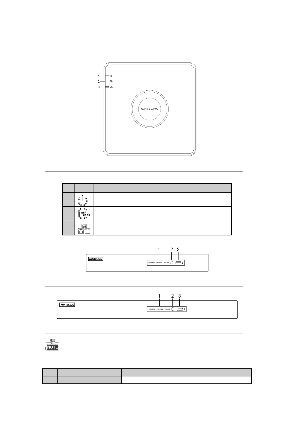
No.
Icon
Description
1 Indicator turns red when DVR is powered up.
2 Indicator lights in red when data is being read from or written to HDD.
3
Indicator blinks blue when network connection is functioning properly.
No.
Name
Function Description
1
POWER
Power indicator turns yellow when the power switch on the real
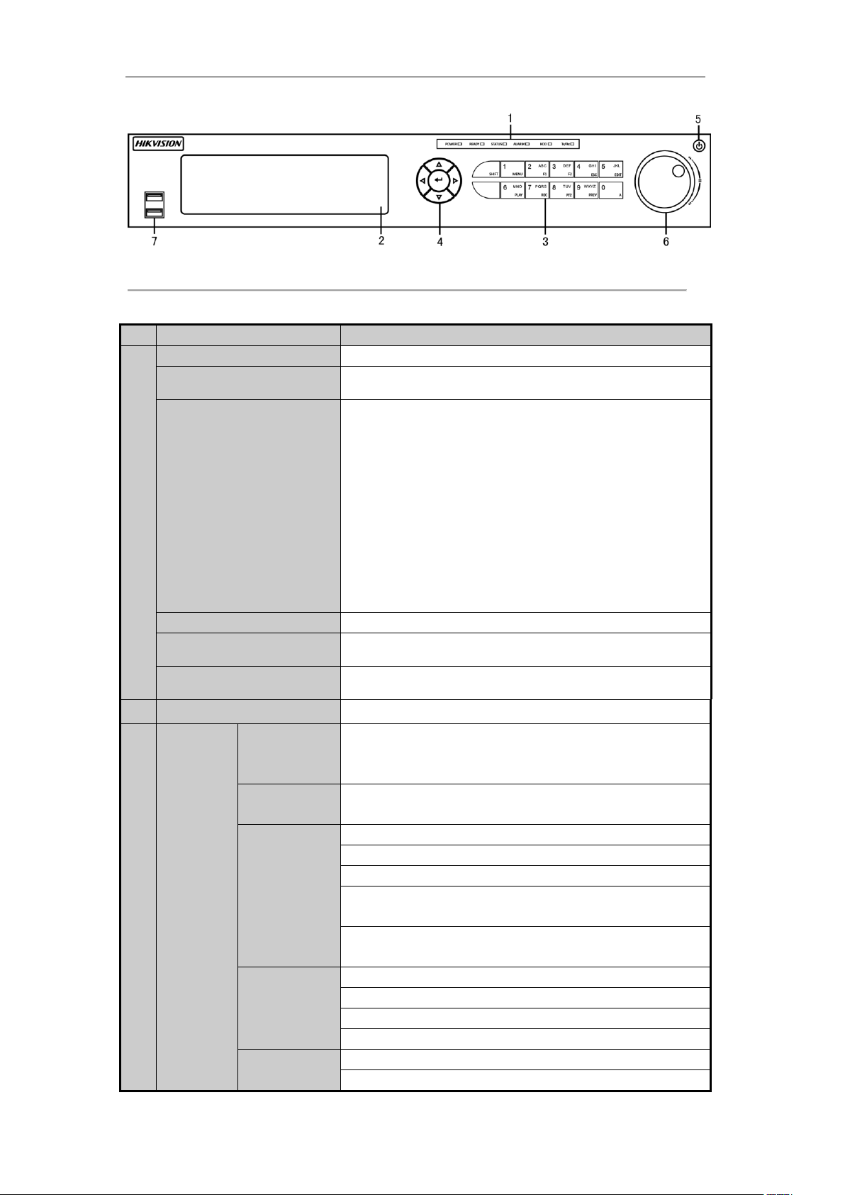
1.1 Front Panels
Figure 1. 1 Front Panel of DS-7100
Table 1. 1 Description of Front Panel
Figure 1. 2 Front Panel of DS-7204/7208HGHI-SH
Figure 1. 3 Front Panel of DS-7216HGHI-SH
Please refer to Figure 1.2 and Figure 1.3 for the front panel of DS-7200HGHI-E1/E2.
Table 1. 2 Description of Front Panel
14
User Manual of Digital Video Recorder
No.
Name
Function Description
panel is turned on.
STATUS
Status indicator blinks red when data is being read from or written to
HDD.
Tx/Rx
Tx/Rx indictor blinks yellow when network connection is
functioning properly.
2
IR Receiver
Receiver for IR remote
3
USB Interfaces
Universal Serial Bus (USB) ports for additional devices such as
USB mouse and USB Hard Disk Drive (HDD).
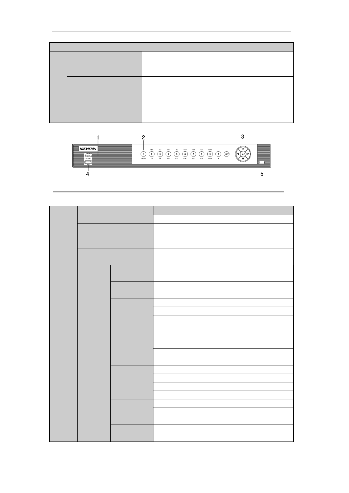
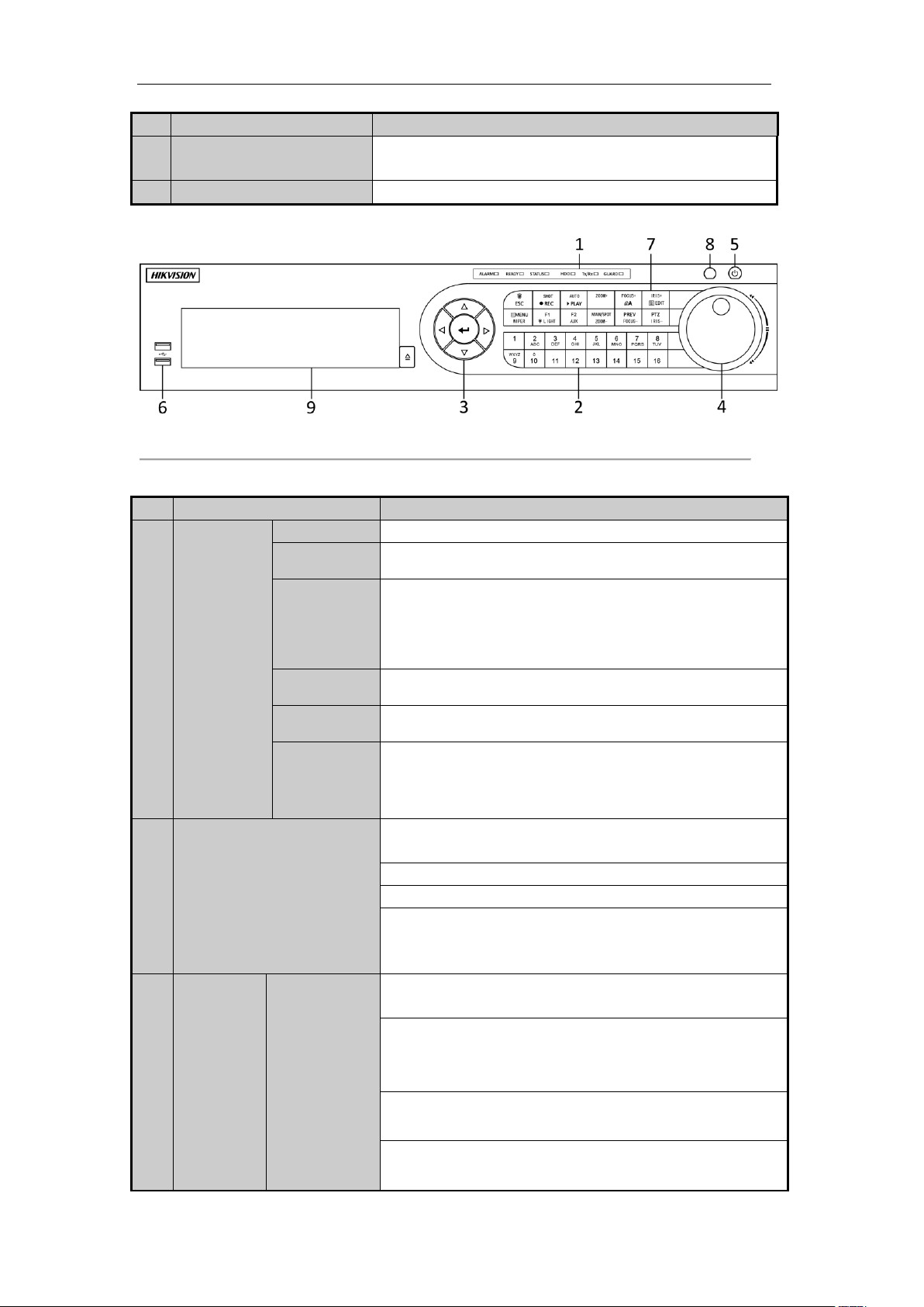
No.
Name
Function Description
1
POWER
Power indicator turns yellow when the device s running.
STATUS
Status indicator blinks red when data is being read from or
written to HDD, and turns yellow when the SHIFT function is
realized.
Tx/Rx
Tx/Rx indictor blinks yellow when network connection is
functioning properly.
2
Composite
Keys
SHIFT
Switch between the numeric or letter input and functions of the
composite keys.
1/MENU
Enter numeral “1”;
Access the main menu interface.
2/ABC/F1
Enter numeral “2”;
Enter letters “ABC”;
The F1 button when used in a list field will select all items in
the list.
In PTZ Control mode, it will turn on/off PTZ light and when
the image is zoomed in, the key is used to zoom out.
In live view or playback mode, the F1 button can be used to
switch between main and spot video output.
3/DEF/F2
Enter numeral “3”;
Enter letters “DEF”;
The F2 button is used to change the tab pages.
In PTZ control mode, it zooms in the image.
4/GHI/ESC
Enter numeral “4”;
Enter letters “GHI”;
Exit and back to the previous menu.
5/JKL/EDIT
Enter numeral “5”;
Enter letters “JKL”;
Figure 1. 4 Front Panel of DS-7200HQHI-SH
Table 1. 3 Description of Front Panel
15
User Manual of Digital Video Recorder
No.
Name
Function Description
Delete characters before cursor;
Check the checkbox and select the ON/OFF switch;
Start/stop record clipping in playback.
6/MNO/PLAY
Enter numeral “6”;
Enter letters “MNO”;
In Playback mode, it is used for direct access to playback
interface.
7/PQRS/REC
Enter numeral “7”;
Enter letters “PQRS”;
Manual record, for direct access to manual record interface;
manually enable/disable record.
8/TUV/PTZ
Enter numeral “8”;
Enter letters “TUV”;
Access PTZ control interface.
9/WXYZ/PREV
Enter numeral “9”;
Enter letters “WXYZ”;
Multi-channel display in live view.
0/A
Enter numeral “0”;
Shift the input methods in the editing text field. (Upper and
lowercase, alphabet, symbols or numeric input).
3
DIRECTION
The DIRECTION buttons are used to navigate between
different fields and items in menus.
In the Playback mode, the Up and Down button is used to
speed up and slow down recorded video. The Left and Right
button will select the next and previous record files.
In Live View mode, these buttons can be used to cycle through
channels.
In PTZ control mode, it can control the movement of the PTZ
camera.
ENTER
The ENTER button is used to confirm selection in any of the
menu modes.
It can also be used to tick checkbox fields.
In Playback mode, it can be used to play or pause the video.
In single-frame Playback mode, pressing the button will
advance the video by a single frame.
In Auto-switch mode, it can be used to stop /start auto switch.
4
USB Interface
Universal Serial Bus (USB) ports for additional devices such
as USB mouse and USB Hard Disk Drive (HDD).
5
IR Receiver
Receiver for IR remote control.
16
User Manual of Digital Video Recorder
No.
Name
Function Description
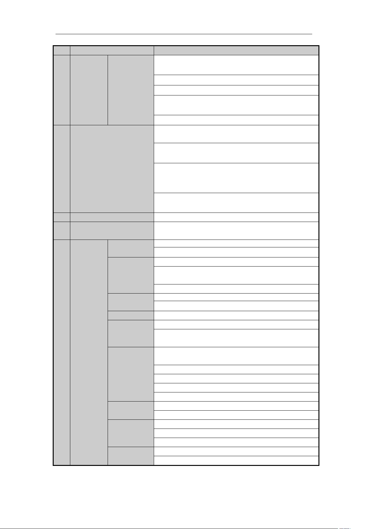
1
POWER
Power indicator lights in green when DVR is powered up.
READY
Ready indicator is normally green, indicating that the DVR is
functioning properly.
STATUS
Indicator turns green when DVR is controlled by an IR remote
control with the address from 1~254;
Indicator turns red when the SHIFT button is used;
Indicator does not light when the DVR is controlled by a keyboard or
by the IR remote control with the address of 255;
Indicator turns green when the DVR is controlled by IR remote
control (with the address from 1~254) and keyboard at the same
time , and the SHIFT button is not used;
Indicator turns orange : (a) when the DVR is controlled by IR remote
control (with the address from 1~254) and keyboard at the same time
and the SHIFT button is used as well; (b) when the DVR is
controlled by IR remote control (with the address from 1~254) and
the SHIFT button is used.
ALARM
Alarm indicator turns red when a sensor alarm is detected.
HDD
HDD indicator blinks in red when data is being read from or written
to HDD.
Tx/Rx
Tx/Rx indictor blinks in green when network connection is
functioning properly.
2
DVD-R/W
Slot for DVD-R/W.
3
Composite
Keys
SHIFT
Switch between the numeric or letter input and functions of the
composite keys. (Input letter or numbers when the light is out;
Realize functions when the light is red.)
1/MENU
Enter numeral “1”;
Access the main menu interface.
2/ABC/F1
Enter numeral “2”;
Enter letters “ABC”;
The F1 button when used in a list field will select all items in the list.
In PTZ Control mode, it will turn on/off PTZ light and when the
image is zoomed in, the key is used to zoom out.
In live view or playback mode, the F1 button can be used to switch
between main and spot video output.
3/DEF/F2
Enter numeral “3”;
Enter letters “DEF”;
The F2 button is used to change the tab pages.
In PTZ control mode, it zooms in the image.
4/GHI/ESC
Enter numeral “4”;
Enter letters “GHI”;
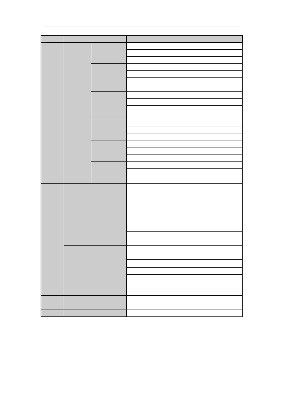
Figure 1. 5 Front Panel of DS-7300HGHI-SH and DS-7300HQHI-SH
Table 1. 4 Description of Front Panel
17

User Manual of Digital Video Recorder
No.
Name
Function Description
Exit and back to the previous menu.
5/JKL/EDIT
Enter numeral “5”;
Enter letters “JKL”;
Delete characters before cursor;
Check the checkbox and select the ON/OFF switch;
Start/stop record clipping in playback.
6/MNO/PLAY
Enter numeral “6”;
Enter letters “MNO”;
In Playback mode, it is used for direct access to playback interface.
7/PQRS/REC
Enter numeral “7”;
Enter letters “PQRS”;
Manual record, for direct access to manual record interface;
manually enable/disable record.
8/TUV/PTZ
Enter numeral “8”;
Enter letters “TUV”;
Access PTZ control interface.
9/WXYZ/PREV
Enter numeral “9”;
Enter letters “WXYZ”;
Multi-channel display in live view.
0/A
Enter numeral “0”;
Shift the input methods in the editing text field. (Upper and
lowercase, alphabet, symbols or numeric input).
4
DIRECTION
The DIRECTION buttons are used to navigate between different
fields and items in menus.
In the Playback mode, the Up and Down button is used to speed up
and slow down recorded video. The Left and Right button will select
the next and previous record files.
In Live View mode, these buttons can be used to cycle through
channels.
In PTZ control mode, it can control the movement of the PTZ
camera.
ENTER
The ENTER button is used to confirm selection in any of the menu
modes.
It can also be used to tick checkbox fields.
In Playback mode, it can be used to play or pause the video.
In single-frame Playback mode, pressing the button will advance the
video by a single frame.
In Auto-switch mode, it can be used to stop /start auto switch.
5
POWER
Power on/off switch.
6
JOG SHUTTLE Control
Move the active selection in a menu. It will move the selection up
and down.
In Live View mode, it can be used to cycle through different
channels.
In the Playback mode, it can be used to jump 30s forward/backward
in video files.
In PTZ control mode, it can control the movement of the PTZ
camera.
18
User Manual of Digital Video Recorder
No.
Name
Function Description
7
USB Interface
Universal Serial Bus (USB) ports for additional devices such as USB
mouse and USB Hard Disk Drive (HDD).
8
IR Receiver
Receiver for IR remote control.
No.
Name
Function Description
1
Status
Indicators
ALARM
Alarm indicator turns red when a sensor alarm is detected.
READY
Ready indicator is normally blue, indicating that the DVR is
functioning properly.
STATUS
Indicator turns blue when DVR is controlled by an IR remote.
Indicator turns red when controlled by a keyboard and orange when
IR remote and keyboard is used at the same time.
Indicator does not light when the DVR is controlled by the IR remote
control with the address of 255.
HDD
HDD indicator blinks in red when data is being read from or written
to HDD.
Tx/Rx
Tx/Rx indictor blinks in blue when network connection is functioning
properly.
GUARD
Indicator turns blue when the device is armed;
Indicator does not light when the device is disarmed;
The arm/disarm state can be initiated by pressing and holding on the
ESC button for more than 3 seconds in live view mode.
2
Alphanumeric Buttons
Switch to the corresponding channel in Live view or PTZ Control
mode.
Input numbers and characters in Edit mode.
Switch between different channels in Playback mode.
The light of the button is blue when the corresponding channel is
recording; it is red when the channel is in network transmission
status; it is pink when the channel is recording and transmitting.
3
Control
Buttons
DIRECTION
The DIRECTION buttons are used to navigate between different
fields and items in menus.
In the Playback mode, the Up and Down button is used to speed up
and slow down recorded video. The Left and Right button will select
the next and previous record files.
In Live View mode, these buttons can be used to cycle through
channels.
In PTZ control mode, it can control the movement of the PTZ
camera.
Figure 1. 6 Front Panel of DS-8100-SH
Table 1. 5 Description of Front Panel
19
User Manual of Digital Video Recorder
No.
Name
Function Description
ENTER
The ENTER button is used to confirm selection in any of the menu
modes.
It can also be used to tick checkbox fields.
In Playback mode, it can be used to play or pause the video.
In single-frame Playback mode, pressing the button will advance the
video by a single frame.
In Auto-switch mode, it can be used to stop /start auto switch.
4
JOG SHUTTLE Control
Move the active selection in a menu. It will move the selection up
and down.
In Live View mode, it can be used to cycle through different
channels.
In the Playback mode: the outer ring is used to speed up or slow
down the record files and the inner ring is used to jump 30s
forward/backward in records files.
In PTZ control mode, it can control the movement of the PTZ
camera.
5
POWER
Power on/off switch.
6
USB Interfaces
Universal Serial Bus (USB) ports for additional devices such as USB
mouse and USB Hard Disk Drive (HDD).
7
Composite
Keys
ESC
Exit and back to the previous menu.
Arm/disarm the DVR in live view mode.
REC/SHOT
Enter the Manual Record setting menu.
In PTZ control settings, press the button and then you can call a PTZ
preset by pressing Numeric button.
It is also used to turn audio on/off in the Playback mode.
PLAY/AUTO
Enter the Playback menu;
Auto scan in the PTZ Control mode.
ZOOM+
Zoom in the PTZ camera in the PTZ Control setting.
A/FOCUS+
Adjust focus in the PTZ Control menu.
It is also used to switch between input methods (upper and lowercase
alphabet, symbols and numeric input).
EDIT/IRIS+
Edit text fields. When editing text fields, it will also function as a
Backspace button to delete the character in front of the cursor.
On checkbox fields, pressing the button will tick the checkbox.
In PTZ Control mode, the button adjusts the iris of the camera.
In Playback mode, it can be used to generate video clips for backup.
Enter/exit the folder of USB device and eSATA HDD.
MAIN/SPOT/Z
OOM-
Switch between main and spot output.
In PTZ Control mode, it can be used to zoom out the image.
F1/ LIGHT
Select all items on the list when used in a list field.
In PTZ Control mode, it will turn on/off PTZ light (if applicable).
In Playback mode, it is used to switch between play and reverse play.
F2/ AUX
Cycle through tab pages.
In synchronous playback mode, it is used to switch between channels.
20
User Manual of Digital Video Recorder
No.
Name
Function Description
MENU/WIPER
Press the button will help you return to the Main menu (after
successful login).
Press and hold the button for 5 seconds will turn off audible key
beep.
In PTZ Control mode, the MENU/WIPER button will start wiper (if
applicable).
In Playback mode, it is used to show/hide the control interface.
PREV/FOCUS-
Switch between single screen and multi-screen mode.
In PTZ Control mode, it is used to adjust the focus in conjunction
with the A/FOCUS+ button.
PTZ/IRIS-
Enter the PTZ Control mode.
In the PTZ Control mode, it is used to adjust the iris of the PTZ
camera.
8
IR Receiver
Receiver for IR remote control.
9
DVD-R/W
Slot for DVD-R/W.
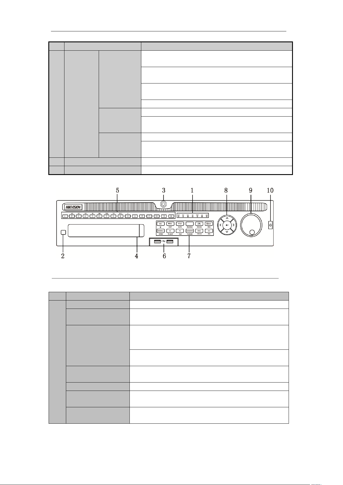
No.
Name
Function Description
1
ALARM
Alarm indicator turns red when a sensor alarm is detected.
READY
Ready indicator is normally blue, indicating that the device is functioning
properly.
STATUS
Status indicator turns blue when device is controlled by an IR remote (if
the device ID# is 255, the indicator is off when the device is controlled
by an IR remote).
Indicator turns red when controlled by a keyboard and purple when IR
remote and keyboard is used at the same time.
HDD
HDD indicator blinks red when data is being read from or written to
HDD.
MODEM
Reserved for future usage.
TX/RX
TX/RX indictor blinks blue when network connection is functioning
properly.
GUARD
Guard indicator turns blue when the device is in armed status; at this
time, an alarm is enabled when an event is detected.
Figure 1. 7 Front Panel of DS-9000HQHI-SH
Table 1. 6 Description of Control Panel Buttons
21

User Manual of Digital Video Recorder
The indicator turns off when the device is unarmed. The arm/disarm
status can be changed by pressing and holding on the ESC button for
more than 3 seconds in live view mode.
2
IR Receiver
Receiver for IR remote
3
Front Panel Lock
You can lock or unlock the panel by the key.
4
DVD-R/W
Slot for DVD-R/W.
5
Alphanumeric Buttons
Switch to the corresponding channel in Live view or PTZ Control mode.
Input numbers and characters in Edit mode.
Switch channels in Playback mode.
The light of the button is blue when the corresponding channel is
recording; it is red when the channel is in network transmission status; it
is pink when the channel is recording and transmitting.
6
USB Interfaces
Universal Serial Bus (USB) ports for additional devices such as USB
mouse and USB Hard Disk Drive (HDD).
7
ESC
Back to the previous menu.
Press for arming/disarming the device in Live View mode.
REC/SHOT
Enter the Manual Record setting menu.
In PTZ control settings, press the button and then you can call a PTZ
preset by pressing Numeric button.
It is also used to turn audio on/off in the Playback mode.
PLAY/AUTO
The button is used to enter the Playback mode.
It is also used to auto scan in the PTZ Control menu.
ZOOM+
Zoom in the PTZ camera in the PTZ Control setting.
A/FOCUS+
Adjust focus in the PTZ Control menu.
It is also used to switch input methods (upper and lowercase alphabet,
symbols and numeric input).
EDIT/IRIS+
Edit text fields. When editing text fields, it will also function as a
Backspace button to delete the character in front of the cursor.
On checkbox fields, pressing the button will tick the checkbox.
In PTZ Control mode, the button adjusts the iris of the camera.
In Playback mode, it can be used to generate video clips for backup.
Enter/exit the folder of USB device and eSATA HDD.
MAIN/SPOT/ZOOM-
Switch main and spot output.
In PTZ Control mode, it can be used to zoom out the image.
F1/ LIGHT
Select all items on the list when used in a list field.
In PTZ Control mode, it will turn on/off PTZ light (if applicable).
In Playback mode, it is used to switch play and reverse play.
F2/ AUX
Cycle through tab pages.
In synchronous playback mode, it is used to switch channels.
MENU/WIPER
Press the button will help you return to the Main menu (after successful
login).
Press and hold the button for 5 seconds will turn off audible key beep.
In PTZ Control mode, the MENU/WIPER button will start wiper (if
applicable).
In Playback mode, it is used to show/hide the control toolbar.
PREV/FOCUS-
Switch single screen and multi-screen mode.
22

User Manual of Digital Video Recorder
In PTZ Control mode, it is used to adjust the focus in conjunction with
the A/FOCUS+ button.
PTZ/IRIS-
Enter the PTZ Control mode.
In the PTZ Control mode, it is used to adjust the iris of the PTZ camera.
8
DIRECTION
The DIRECTION buttons are used to navigate between different fields
and items in menus.
In the Playback mode, the Up and Down button is used to speed up and
slow down recorded video. The Left and Right button will select the next
and previous record files.
In Live View mode, these buttons can be used to cycle through channels.
In PTZ control mode, it can control the movement of the PTZ camera.
ENTER
The ENTER button is used to confirm selection in any of the menu
modes.
It can also be used to tick checkbox fields.
In Playback mode, it can be used to play or pause the video.
In single-frame Playback mode, pressing the button will advance the
video by a single frame.
In Auto-switch mode, it can be used to stop /start auto switch.
9
JOG SHUTTLE Control
Move the active selection in a menu. It will move the selection up and
down.
In Live View mode, it can be used to cycle through different channels.
In the Playback mode: the ring is used to jump 30s forward/backward
in video files.
In PTZ control mode, it can control the movement of the PTZ camera.
10
POWER ON/OFF
Power on/off switch.
23
User Manual of Digital Video Recorder
No.
Name
Description
1
POWER
Power on/off the device.
Power on/off the device by pressing and holding the button for 3 seconds.
2
MENU Button
Press the button to return to the main menu (after successful login).
Press and hold the button for 5 seconds will turn off audible key beep.
In PTZ Control mode, the MENU button will start wiper (if applicable).
In Playback mode, it is used to show/hide the control interface.
3
REC Button
Enter the Manual Record setting menu.
In PTZ control settings, press the button and then you can call a PTZ preset
by pressing Numeric button.
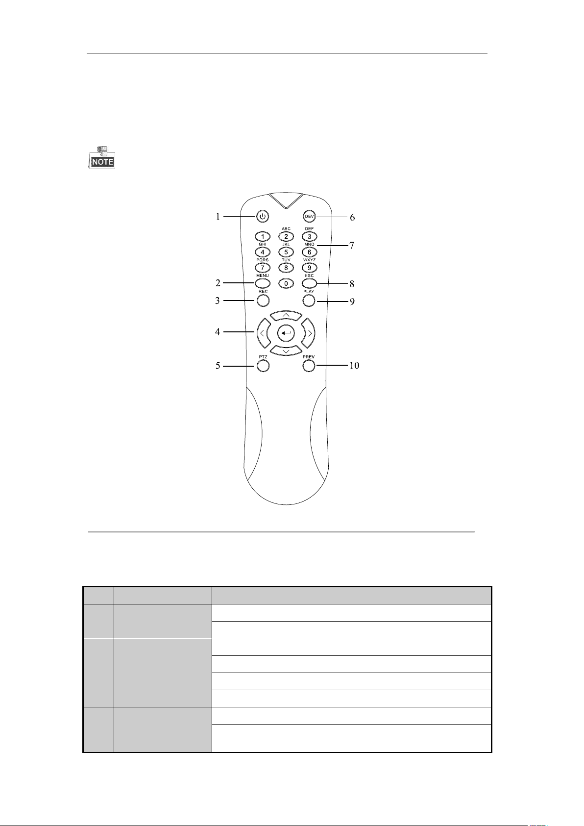
1.2 IR Remote Control Operations
The DVR may also be controlled with the included IR remote control, shown in Figure 1. 8.
Batteries (2×AAA) must be installed before operation.
Figure 1. 8 Remote Control
The keys on the remote control closely resemble the ones found on the front panel. Refer to Table 1. 7, they
include:
Table 1. 7 Description of the IR Remote Control Buttons
24

User Manual of Digital Video Recorder
No.
Name
Description
It is also used to turn audio on/off in the Playback mode.
4
DIRECTION Button
Navigate between different fields and items in menus.
In the Playback mode, the Up and Down button is used to speed up and
slow down recorded video. The Left and Right button will select the next
and previous record files.
In Live View mode, these buttons can be used to cycle through channels.
In PTZ control mode, it can control the movement of the PTZ camera.
ENTER Button
Confirm selection in any of the menu modes.
It can also be used to tick checkbox fields.
In Playback mode, it can be used to play or pause the video.
In single-frame Playback mode, pressing the button will advance the video
by a single frame.
5
PTZ Button
In Auto-switch mode, it can be used to stop /start auto switch.
6
DEV
Enables/Disables Remote Control.
7
Alphanumeric Buttons
Switch to the corresponding channel in Live view or PTZ Control mode.
Input numbers and characters in Edit mode.
Switch between different channels in the Playback mode.
8
ESC Button
Back to the previous menu.
Press for Arming/disarming the device in Live View mode.
9
PLAY Button
The button is used to enter the All-day Playback mode.
It is also used to auto scan in the PTZ Control menu.
10
PREV Button
Switch between single screen and multi-screen mode.
In PTZ Control mode, it is used to adjust the focus in conjunction with the
A/FOCUS+ button.
Troubleshooting Remote Control:
Make sure you have install batteries properly in the remote control. And you have to aim the remote control at
the IR receiver in the front panel.
If there is no response after you press any button on the remote, follow the procedure below to troubleshoot.
Steps:
1. Go into Menu > Settings > General > More Settings by operating the front control panel or the mouse.
2. Check and remember the DVR No.. The default DVR No. is 255. This number valid for all IR remote
controls.
3. Press the DEV button on the remote control.
4. Enter the DVR No. in step 2.
5. Press the ENTER button on the remote.
If the Status indicator on the front panel turns blue, the remote control is operating properly. If the Status
indicator does not turn blue and there is still no response from the remote, please check the following:
1. Batteries are installed correctly and the polarities of the batteries are not reversed.
25

User Manual of Digital Video Recorder
2. Batteries are fresh and not out of charge.
3. IR receiver is not obstructed.
If the remote still cannot function properly, please change the remote and try again, or contact the device
provider.
26

User Manual of Digital Video Recorder
Name
Action
Description
Left-Click
Single-Click
Live view: Select channel and show the quick set menu.
Menu: Select and enter.
Double-Click
Live view: Switch between single-screen and multi-screen.
Click and Drag
PTZ control: Wheeling.
Privacy mask and motion detection: Select target area.
Digital zoom-in: Drag and select target area.
Live view: Drag channel/time bar.
Right-Click
Single-Click
Live view: Show menu.
Menu: Exit current menu to upper level menu.
Scroll-Wheel
Scrolling up
Live view: Previous screen.
Menu: Previous item.
Scrolling down
Live view: Next screen.
Menu: Next item.
1.3 USB Mouse Operation
A regular 3-button (Left/Right/Scroll-wheel) USB mouse can also be used with this DVR. To use a USB mouse:
Steps:
1. Plug USB mouse into one of the USB interfaces on the front panel of the DVR.
2. The mouse should automatically be detected. If in a rare case that the mouse is not detected, the possible
reason may be that the two devices are not compatible, please refer to the recommended the device list
from your provider.
The operation of the mouse:
Table 1. 8 Description of the Mouse Control
27
User Manual of Digital Video Recorder
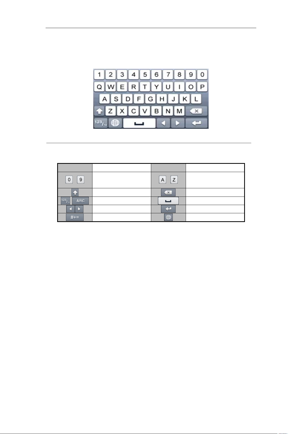
Icon
Description
Icon
Description
…
Number
…
English letter
Lowercase/Uppercase
Backspace
Switch the keyboard
Space
Positioning the cursor
Exit
Symbols
Reserved
1.4 Input Method Description
Figure 1. 9 Soft Keyboard
Description of the buttons on the soft keyboard:
Table 1. 9 Description of the Soft Keyboard Icons
28
User Manual of Digital Video Recorder
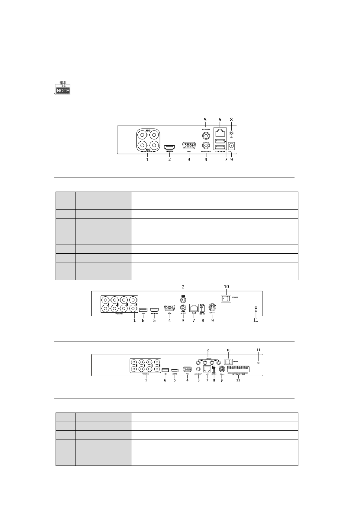
No.
Item
Description
1
VIDEO IN
BNC interface for TVI and analog video input.
2
HDMI
HDMI video output connector.
3
VGA
DB15 connector for VGA output. Display local video output and menu.
4
AUDIO OUT
RCA connector.
5
AUDIO IN
RCA connector.
6
Network Interface
Connector for network
7
USB Port
Universal Serial Bus (USB) port for additional devices.
8
GND
Ground
9
Power Supply
DC 12V power supply.
No.
Item
Description
1
VIDEO IN
BNC interface for TVI and analog video input.
2
AUDIO IN
RCA connector
3
AUDIO OUT
RCA connector
4
VGA
DB15 connector for VGA output. Display local video output and menu.
5
HDMI
HDMI video output connector.
1.5 Rear Panel
The rear panel vaires according to different models. Please refer to the actual product. The following figures are
for reference only.
Figure 1. 10 DS-7100
Table 1. 10 Description of Front Panel
Figure 1. 11 DS-7200HGHI
Figure 1. 12 DS-7200HQHI
Table 1. 11 Description of Front Panel
29

User Manual of Digital Video Recorder
6
USB Port
Universal Serial Bus (USB) port for additional devices.
7
Network Interface
Connector for network
8
RS-485 Interface
Connector for RS-485 devices.
9
Power Supply
12V DC power supply.
10
Power Switch
Switch for turning on/off the device.
11
GND
Ground
12
Alarm In/Out (for
DS-7200HQHI-SH
only)
Connectors for alarm inputs and alarm outputs.
Figure 1. 13 DS-7316HQHI-SH and DS-7316HGHI-SH
Figure 1. 14 DS-7332HGHI-SH
Figure 1. 15 DS-8116HGHI-SH
30
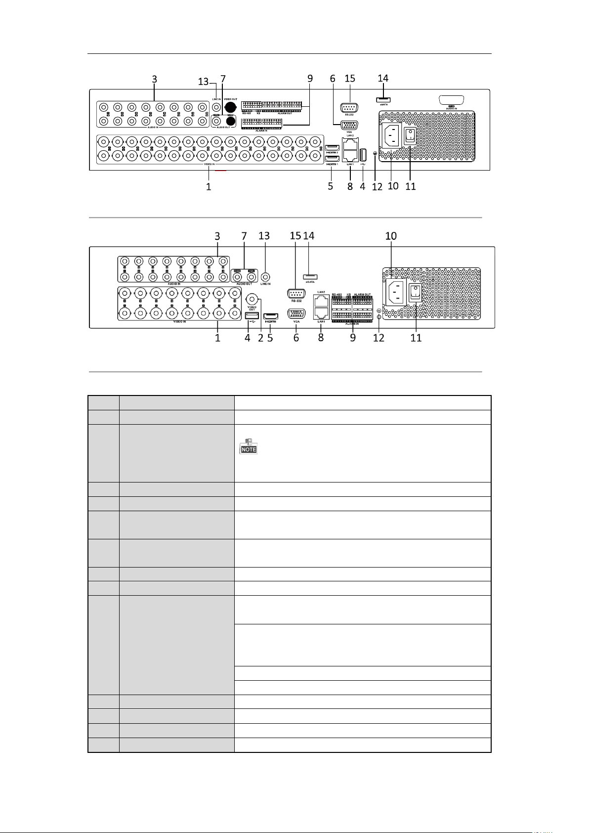
User Manual of Digital Video Recorder
No.
Item
Description
1
VIDEO IN
BNC interface for TVI and analog video input.
2
VIDEO OUT
BNC connector for video output.
CVBS output is not provided by DS-7324/7332HGHI-SH and
DS-8124/8132HGHI-SH series.
3
AUDIO IN
RCA connector
4
USB Port
Universal Serial Bus (USB) port for additional devices.
5
HDMI
HDMI video output connector.
DS-8124/8132HGHI-SH provides HDMI1 and HDMI2 interfaces.
6
VGA
DB15 connector for VGA output. Display local video output and
menu.
7
AUDIO OUT
RCA connector.
8
Network Interface
Connector for network
9
RS-485 Interface
Connector for RS-485 devices. T+ and T- pins connect to R+ and Rpins of PTZ receiver respectively.
D+, D- pin connects to Ta, Tb pin of controller. For cascading
devices, the first DVR’s D+, D- pin should be connected with the
D+, D- pin of the next DVR.
Connector for alarm input.
Connector for alarm output.
10
Power Supply
100 ~ 240V AC power supply.
11
Power Switch
Switch for turning on/off the device.
12
GND
Ground
13
LINE IN
BNC connector for audio input.
Figure 1. 16 DS-8132HGHI-SH
Figure 1. 17 DS-8100/9000HQHI-SH
Table 1. 12 Description of Front Panel
31

User Manual of Digital Video Recorder
No.
Item
Description
14
eSATA
Connects external SATA HDD, CD/DVD-RW.
15
RS-232 Interface
Connector for RS-232 devices.
32

User Manual of Digital Video Recorder
Chapter 2 Getting Started
33
User Manual of Digital Video Recorder
2.1 Starting Up and Shutting Down the DVR
Purpose:
Proper startup and shutdown procedures are crucial to expanding the life of the DVR.
Before you start:
Check that the voltage of the extra power supply is the same with the DVR’s requirement, and the ground
connection is working properly.
Starting up the DVR
Steps:
1. Check the power supply is plugged into an electrical outlet. It is HIGHLY recommended that an
Uninterruptible Power Supply (UPS) be used in conjunction with the device.
2. Turn on the power switch on the rear panel, and the Power indicator LED should turn on indicating that
the unit begins to start up.
3. After startup, the Power indicator LED remains on.
Shutting down the DVR
Steps:
There are two proper ways to shut down the DVR. To shut down the DVR:
OPTION 1: Standard shutdown
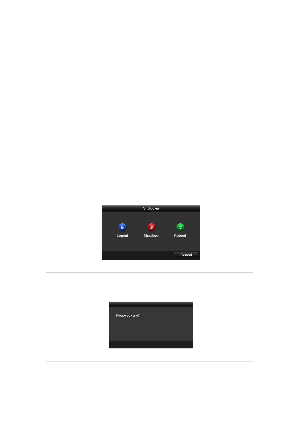
1. Enter the Shutdown menu.
Menu > Shutdown
Figure 2. 1 Shutdown Menu
2. Select the Shutdown button.
3. Click the Yes button.
4. Turn off the power switch on the rear panel when the note appears (for DS-7200 and DS-7100 series).
Figure 2. 2 Shutdown Tips
OPTION 2: By operating the front panel (for DS-7300 and DS-8100 series)
1. Press and hold the POWER button on the front panel for 3 seconds.
2. Enter the administrator’s username and password in the dialog box for authentication.
3. Click the Yes button.
34

User Manual of Digital Video Recorder
Do not press the POWER button again when the system is shutting down.
The device remains standby mode after shutting down, and the POWER indicator turns red; you can
turn on the device by pressing the POWER button on the remote control.
Rebooting the DVR
While in the Shutdown menu (Figure 2. 1), you can also reboot the DVR.
Steps:
1. Enter the Shutdown menu by clicking Menu > Shutdown.
2. Click the Logout button to log out or the Reboot button to reboot the DVR.
35
User Manual of Digital Video Recorder
2.2 Setting the Admin Password
Purpose:
For the first-time access, you need to activate the device by setting an admin password. No operation is allowed
before activation. You can also activate the device via Web Browser, SADP or Client Software.
Steps:
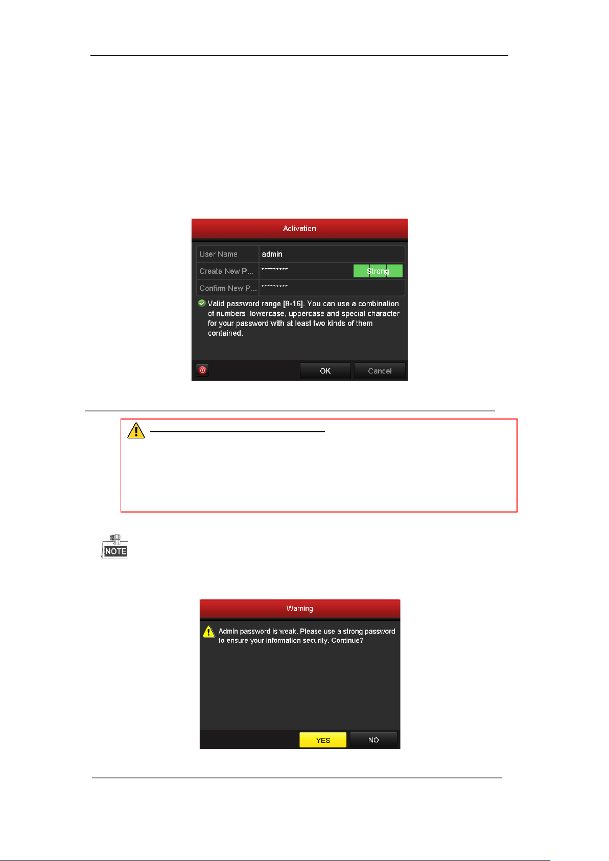
1. Input the same password in the text field of Create New Password and Confirm New Password.
Figure 2. 3 Settings Admin Password
STRONG PASSWORD RECOMMENDED– We highly recommend you create a strong
password of your own choosing (using a minimum of 8 characters, including upper case
letters, lower case letters, numbers, and special characters) in order to increase the security
of your product. And we recommend you reset your password regularly, especially in the high
security system, resetting the password monthly or weekly can better protect your product.
2. Click OK to save the password and activate the device.
For the old version device, if you update it to the new version, the following dialog box will pop up once the
device starts up. You can click YES and follow the wizard to set a strong password.
Figure 2. 4 Warning
36

User Manual of Digital Video Recorder
2.3 Using the Wizard for Basic Configuration
By default, the Setup Wizard starts once the device has loaded.
Figure 2. 5 Start Wizard Interface
Operating the Setup Wizard:
1. The Start Wizard can walk you through some important settings of the device. If you don’t want to use the
Start Wizard at that moment, click Exit. You can also choose to use the Start Wizard next time by leaving
the “Start wizard when device starts?” checkbox checked.
2. Click Next to enter the date and time settings window.
Figure 2. 6 Date and Time Settings
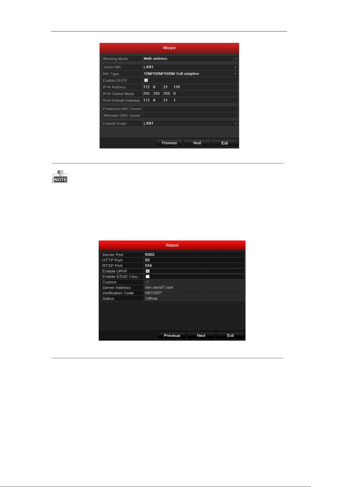
3. After the time settings, click Next button which will take you back to the General Network Setup Wizard
window, as shown in Figure 2. 7.
37
User Manual of Digital Video Recorder
Figure 2. 7 General Network Configuration
1 self-adaptive 10M/100M network interface for DS-7100, DS-7204/7208HGHI-SH and DS-7200HGHI-E1/E2;
2 self-adaptive 10M/100M/1000M network interfaces for DS-8100HQHI&HGHI-SH series, with three working
modes configurable: multi-address, load balance, network fault tolerance; and 1 self-adaptive
10M/100M/1000M network interface for other models.
4. Click Next button after you having configured the network parameters, which will take you to the
Advanced Network Setup Wizard window, as shown in Figure 2. 8.
Figure 2. 8 Advanced Network Configuration
5. Set the parameters of port No., EZVIZ Cloud P2P, Auto UPnP or DDNS if required.
6. Click Next button after configuring the advanced network parameters, which will take you to the HDD
Management window, shown in Figure 2. 9.
38
User Manual of Digital Video Recorder
Figure 2. 9 HDD Management
7. To initialize the HDD, click the Init button. Initialization will remove all the data saved in the HDD.
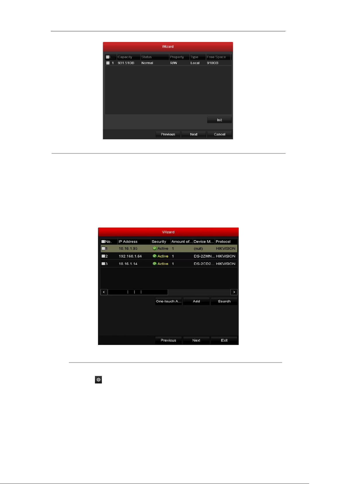
8. Click Next to enter the IP Camera Management window (only supported by HDVR series).
9. Click Search to search the online IP Camera and the Security status shows whether it is active or inactive.
Before adding the camera, make sure the IP camera to be added is in active status.
If the camera is in inactive status, you can click the inactive icon of the camera to set the password to
activate it. You can also select multiple cameras from the list and click the One-touch Activate to activate
the cameras in batch.
Click the Add to add the camera.
Figure 2. 10 IP Camera Management
10. After finishing IP Camera settings, click Next to enter the Record Settings window.
11. Click the icon , and you can enable the continuous recording or motion Detection recording for all
channels of the device.
39

User Manual of Digital Video Recorder
Figure 2. 11 Record Settings
12. Click OK to complete the wizard settings.
40

User Manual of Digital Video Recorder
2.4 Login and Logout
2.4.1 User Login
Purpose:
If the device has logged out, you must login the device before operating the menu and other functions.
Steps:
1. Select the User Name in the dropdown list.
Figure 2. 12 Login Interface
2. Input Password.
3. Click OK to log in.
In the Login dialog box, if you have entered the wrong password for 7 times, the current user account will be
locked for 60 seconds.
Figure 2. 13 User Account Protection
2.4.2 User Logout
Purpose:
After logging out, the monitor turns to the live view mode and if you want to perform some operation, you need
to enter user name and password log in again.
Steps:
1. Enter the Shutdown menu.
Menu > Shutdown
41

User Manual of Digital Video Recorder
Figure 2. 14 Logout
2. Click Logout.
After you have logged out the system, menu operation on the screen is invalid. It is required to input a user
name and password to unlock the system.
42

User Manual of Digital Video Recorder
2.5 Adding and Connecting the IP Cameras
This section is not available for the DS-7100 series DVR.
2.5.1 Setting the Admin Password for the IP Camera
Purpose:
Before adding the camera, make sure the IP camera to be added is in active status.
Steps:
1. Select the Add IP Camera option from the right-click menu in live view mode or click Menu> Camera>
Camera to enter the IP camera management interface.
For the IP camera detected online in the same network segment, the Security status shows whether it is
active or inactive.
Figure 2. 15 IP Camera Management Interface
2. Click the inactive icon of the camera to enter the following interface to activate it. You can also select
multiple cameras from the list and click the One-touch Activate to activate the cameras in batch.
Figure 2. 16 Activate the Camera
43

User Manual of Digital Video Recorder
3. Set the password of the camera to activate it.
Use Admin Password: when you check the checkbox, the camera (s) will be configured with the same
admin password of the operating NVR.
Figure 2. 17 Set New Password
Create New Password: If the admin password is not used, you must create the new password for the
camera and confirm it.
STRONG PASSWORD RECOMMENDED– We highly recommend you create a strong
password of your own choosing (using a minimum of 8 characters, including upper case
letters, lower case letters, numbers, and special characters) in order to increase the security
of your product. And we recommend you reset your password regularly, especially in the high
security system, resetting the password monthly or weekly can better protect your product.
4. Click OK to finish the acitavting of the IP camera. And the security status of camera will be changed to
Active.
2.5.2 Adding the Online IP Cameras
Purpose:
Before you can get a live view or record of the video, you should add the network cameras to the connection list
of the device.
Before you start:
Ensure the network connection is valid and correct. For detailed checking and configuring of the network,
please see Chapter 11.
OPTION 1:
Steps:
1. Select the Add IP Camera option from the right-click menu in live view mode or click Menu> Camera>
Camera to enter the IP camera management interface.
44

User Manual of Digital Video Recorder
Figure 2. 18 Adding IP Camera Interface
2. The online cameras with same network segment will be detected and displayed in the camera list.
3. Select the IP camera from the list and click the button to add the camera (with the same admin
password of the DVR’s). Or you can click the One-touch Adding button to add all cameras (with the same
admin password) from the list.
Make sure the camera to add has already been actiavted by setting the admin password, and the admin
password of the camera is the same with the DVR’s.
4. (For the encoders with multiple channels only) check the checkbox of Channel Port in the pop-up window,
as shown in the following figure, and click OK to add multiple channels.
Figure 2. 19 Selecting Multiple Channels
OPTION 2:
Steps:
1) On the IP Camera Management interface, click the Custom Adding button to pop up the Add IP
45

User Manual of Digital Video Recorder
Camera (Custom) interface.
Figure 2. 20 Custom Adding IP Camera Interface
2) You can edit the IP address, protocol, management port, and other information of the IP camera to be
added.
If the IP camera to add has not been actiavated, you can activate it from the IP camera list on the camera
management interface.
3) Click Add to add the camera.
For the successfully added IP cameras, the Security status shows the security level of the password of
camera: strong password, weak password and risk password.
Figure 2. 21 Successfully Added IP Cameras
For the DS-7200 series DVR, 1-ch or 2-ch IP cameras can be added, and for the DS-7300/8100/9000
series DVR, 1 more IP camera can be added by disabling 1 analog channel, and up to 32 IP cameras
can be added. Please refer to the following table for the number of connectable IP cameras for
different models.
46
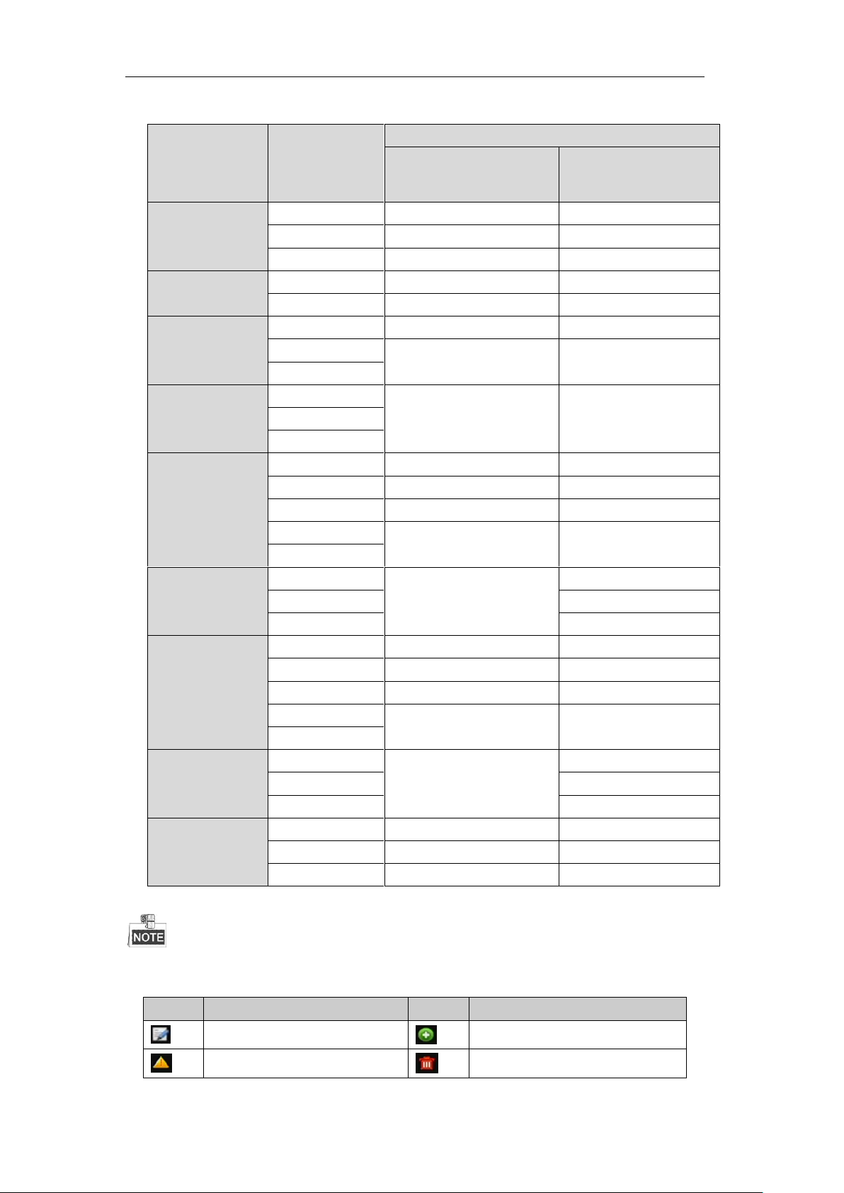
User Manual of Digital Video Recorder
Series
Models
Number of Connectable IP Cameras
Default (without disabling
analog channel)
Max. Number (by disabling
all analog channels)
DS-7200HGHI-E1
DS-7204HGHI-E1
1-ch
1-ch
DS-7208HGHI-E1
2-ch
2-ch
DS-7216HGHI-E1
2-ch
2-ch
DS-7200HGHI-E2
DS-7208HGHI-E2
2-ch
2-ch
DS-7216HGHI-E2
2-ch
2-ch
DS-7200HGHI-SH
DS-7204HGHI-SH
1-ch
1-ch
DS-7208HGHI-SH
2-ch
2-ch
DS-7216HGHI-SH
DS-7200HQHI-SH
DS-7204HQHI-SH
2-ch
2-ch
DS-7208HQHI-SH
DS-7216HQHI-SH
DS-7300HGHI-SH
DS-7304HGHI-SH
1-ch
5-ch
DS-7308HGHI-SH
2-ch
10-ch
DS-7316HGHI-SH
2-ch
18-ch
DS-7324HGHI-SH
8-ch
32-ch
DS-7332HGHI-SH
DS-7300HQHI-SH
DS-7304HQHI-SH
2-ch
6-ch
DS-7308HQHI-SH
10-ch
DS-7316HQHI-SH
18-ch
DS-8100HGHI-SH
DS-8104HGHI-SH
1-ch
5-ch
DS-8108HGHI-SH
2-ch
10-ch
DS-8116HGHI-SH
2-ch
18-ch
DS-8124HGHI-SH
16-ch
32-ch
DS-8132HGHI-SH
DS-8100HQHI-SH
DS-8104HQHI-SH
2-ch
6-ch
DS-8108HQHI-SH
10-ch
DS-8116HQHI-SH
18-ch
DS-9000HQHI-SH
DS-9004HQHI-SH
6-ch
10-ch
DS-9008HQHI-SH
10-ch
18-ch
DS-9016HQHI-SH
18-ch
32-ch
Icon
Explanation
Icon
Explanation
Edit basic parameters of the camera
Add the detected IP camera.
The camera is disconnected; you can
Delete the IP camera
Table 2. 1 Connectable IP Cameras for Different Models
Please refer to the Appendix for the list of compatible IP cameras.
Table 2. 2 Explanation of the icons
47
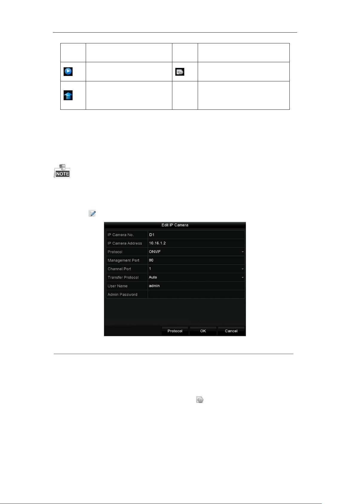
User Manual of Digital Video Recorder
click the icon to get the exception
information of camera.
Play the live video of the connected
camera.
Advanced settings of the camera.
Upgrade the connected IP camera.
Security
Show the security status of the camera
to be active/inactive or the password
strength (strong/medium/weak/risk)
2.5.3 Editing the Connected IP Cameras and Configuring
Customized Protocols
This section is provided for the DS-7300 and DS-8100 models only which support the ONVIF protocol.
After the adding of the IP cameras, the basic information of the camera lists in the page, you can configure the
basic setting of the IP cameras.
Steps:
1. Click the icon to edit the parameters; you can edit the IP address, protocol and other parameters.
Channel Port: If the connected device is an encoding device with multiple channels, you can choose the
channel to connect by selecting the channel port No. in the dropdown list.
2. Click OK to save the settings and exit the editing interface.
To edit advanced parameters:
1. Drag the horizontal scroll bar to the right side and click the icon.
Figure 2. 22 Edit the Parameters
48
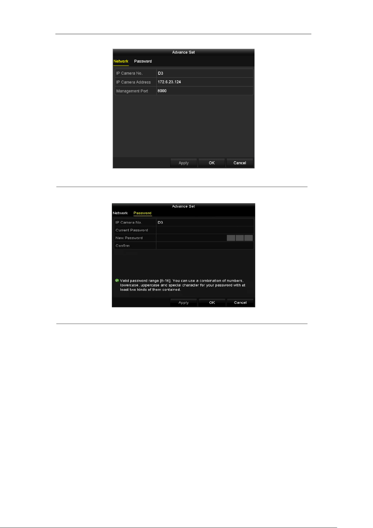
User Manual of Digital Video Recorder
Figure 2. 23 Network Configuration of the Camera
2. You can edit the network information and the password of the camera.
Figure 2. 24 Password Configuration of the Camera
3. Click OK to save the settings and exit the interface.
Configuring the customized protocols
Purpose:
To connect the network cameras which are not configured with the standard protocols, you can configure the
customized protocols for them.
Steps:
1. Click the Protocol button in the custom adding IP camera interface to enter the protocol management
interface.
49
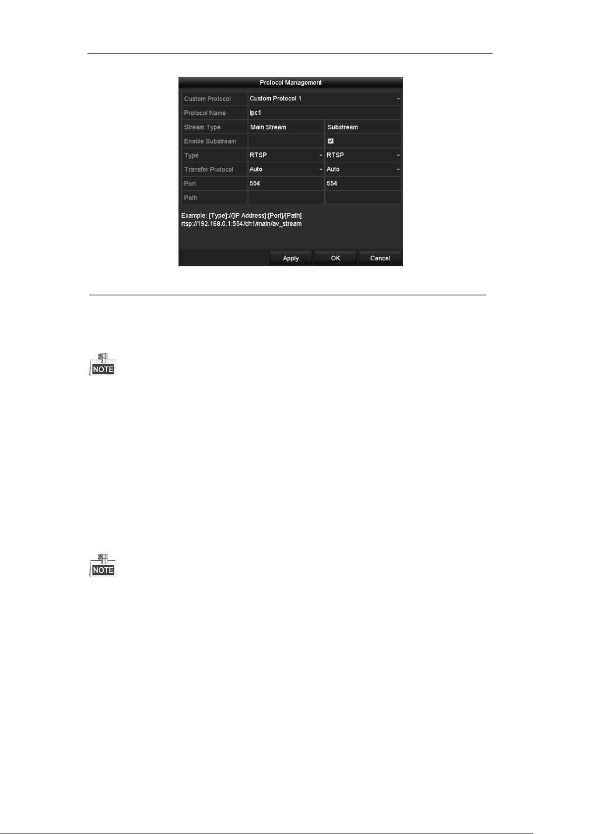
User Manual of Digital Video Recorder
Figure 2. 25 Protocol Management Interface
There are 16 customized protocols provided in the system, you can edit the protocol name; and choose
whether to enable the sub-stream.
2. Choose the protocol type of transmission and choose the transfer protocols.
Before customizing the protocol for the network camera, you have to contact the manufacturer of the network
camera to consult the URL (uniform resource locator) for getting main stream and sub-stream.
The format of the URL is: [Type]://[IP Address of the network camera]:[Port]/[Path].
Example: rtsp://192.168.1.55:554/ch1/main/av_stream.
Protocol Name: Edit the name for the custom protocol.
Enable Substream: If the network camera does not support sub-stream or the sub-stream is not needed
leave the checkbox empty.
Type: The network camera adopting custom protocol must support getting stream through standard RTSP.
Transfer Protocol: Select the transfer protocol for the custom protocol.
Port: Set the port No. for the custom protocol.
Path: Set the resource path for the custom protocol. E.g., ch1/main/av_stream.
The protocol type and the transfer protocols must be supported by the connected network camera.
After adding the customized protocols, you can see the protocol name is listed in the dropdown list, please refer
to Figure 2. 26.
50
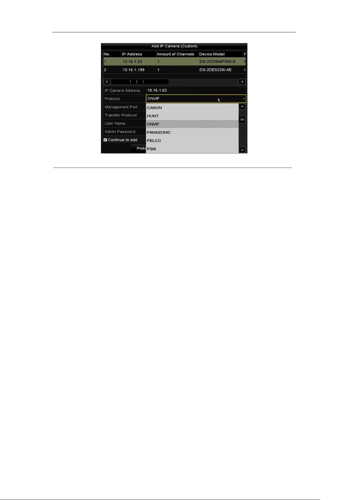
User Manual of Digital Video Recorder
Figure 2. 26 Protocol Setting
3. Choose the protocols you just added to validate the connection of the network camera.
51

User Manual of Digital Video Recorder
Chapter 3 Live View
52

User Manual of Digital Video Recorder
Icons
Description
Alarm (video loss, tampering, motion detection or sensor alarm)
Record (manual record, schedule record, motion detection or alarm triggered record)
Alarm & Record
Event/Exception (motion detection, sensor alarm or exception information. For details,
see Chapter 8.7 Handling Exceptions.)
3.1 Introduction of Live View
Live view shows you the video image getting from each camera in real time. The DVR will automatically enter
Live View mode when powered on. It is also at the very top of the menu hierarchy, thus hitting the ESC many
times (depending on which menu you’re on) will bring you to the Live View mode.
Live View Icons
In the live view mode, there are icons at the right top of the screen for each channel, showing the status of the
record and alarm in the channel, so that you can know whether the channel is recorded, or whether there are
alarms occur as soon as possible.
Table 3. 1 Description of Live View Icons
53
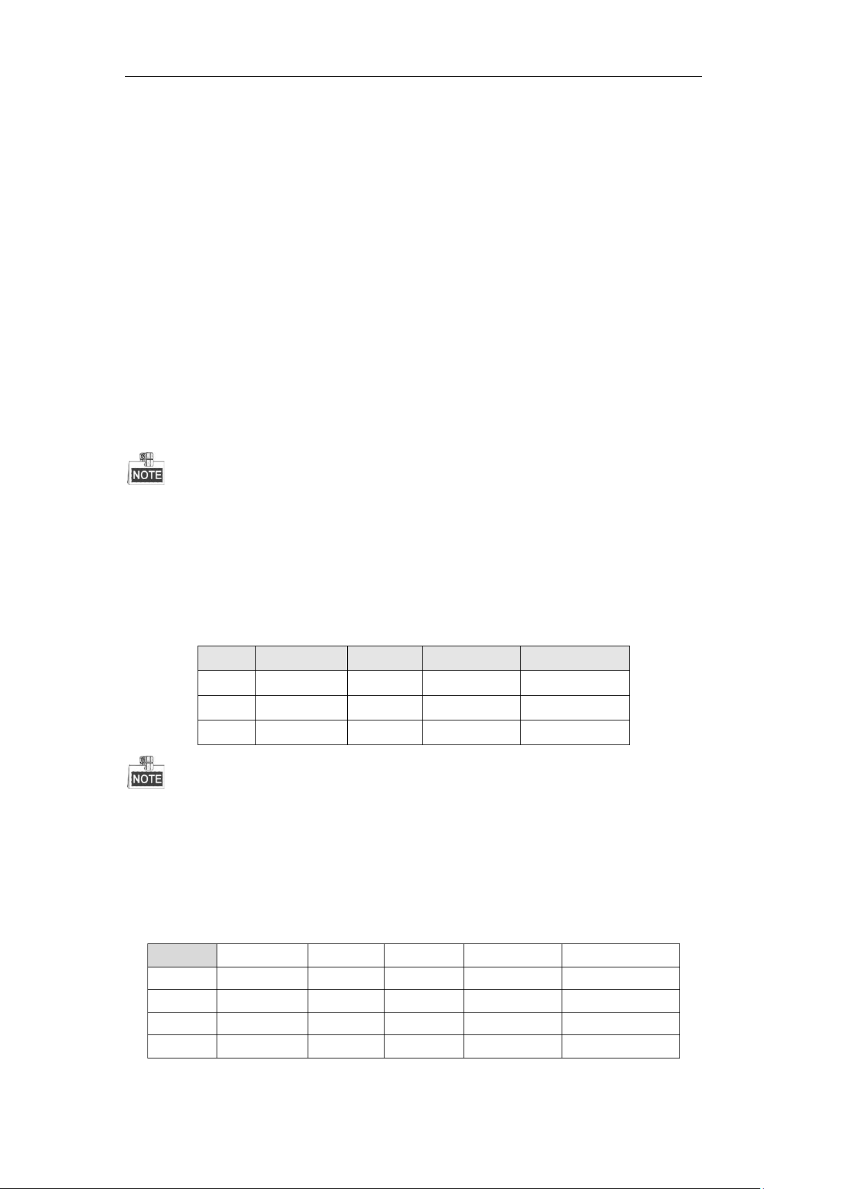
User Manual of Digital Video Recorder
S.N
VGA/HDMI1
HDMI2
Main output
Auxiliary output
1 √ √
VGA/HDMI1
HDMI2
2 √ ×
VGA/HDMI1
3 × √
HDMI2
S.N
HDMI
VGA
CVBS
Main output
Auxiliary output
1
√ √ √
HDMI
VGA
2
√ × √
HDMI
CVBS
3
× √ √
VGA
CVBS
4
× × √
CVBS
3.2 Operations in Live View Mode
In live view mode, there are many functions provided. The functions are listed below.
• Single Screen: show only one screen on the monitor.
• Multi-screen: show multiple screens on the monitor simultaneously.
• Auto-switch: the screen is auto switched to the next one. And you must set the dwell time for each screen
on the configuration menu before enabling the auto-switch. Menu>Configuration>Live View>Dwell
Time.
• Start Recording: normal record and motion detection record are supported.
• Quick Set: select the output mode to Standard, Bright, Gentle or Vivid.
• Playback: play back the recorded videos for current day.
• Aux/Main output switch: the DVR checks the connection of the output interfaces to define the main and
auxiliary output interfaces. When the aux output is enabled, the main output cannot do any operation, and
you can do some basic operation on the live view mode for the Aux output.
The DS-7100, DS-7200, and DS-7324/7332HGHI-SH models do not support Aux/Main output switch.
The priority level for the main and aux output for other models is as follows:
For the DS-8124/8132HGHI-SH
The DS-8124/8132HGHI-SH provides HDMI1, HDMI2 and VGA interfaces, and the priority level for the main
and aux output is HDMI1/VGA>HDMI2. See the table below.
Table 3. 2 Priorities of Interfaces
The √ means the interface is in use, × means the interface is out of use or the connection is invalid. And the
HDMI1, VGA and HDMI2 can be used at the same time.
For the DS-7308/7316HQHI-SH and DS-8108/8116HQHI-SH
The DS-7308/7316HQHI-SH and DS-8108/8116HQHI-SH provide the independent HDMI and VGA outputs,
and CVBS output. The priority level for the main and aux output is HDMI>VGA>CVBS. See the table below.
Table 3. 3 Priorities of Interfaces
54
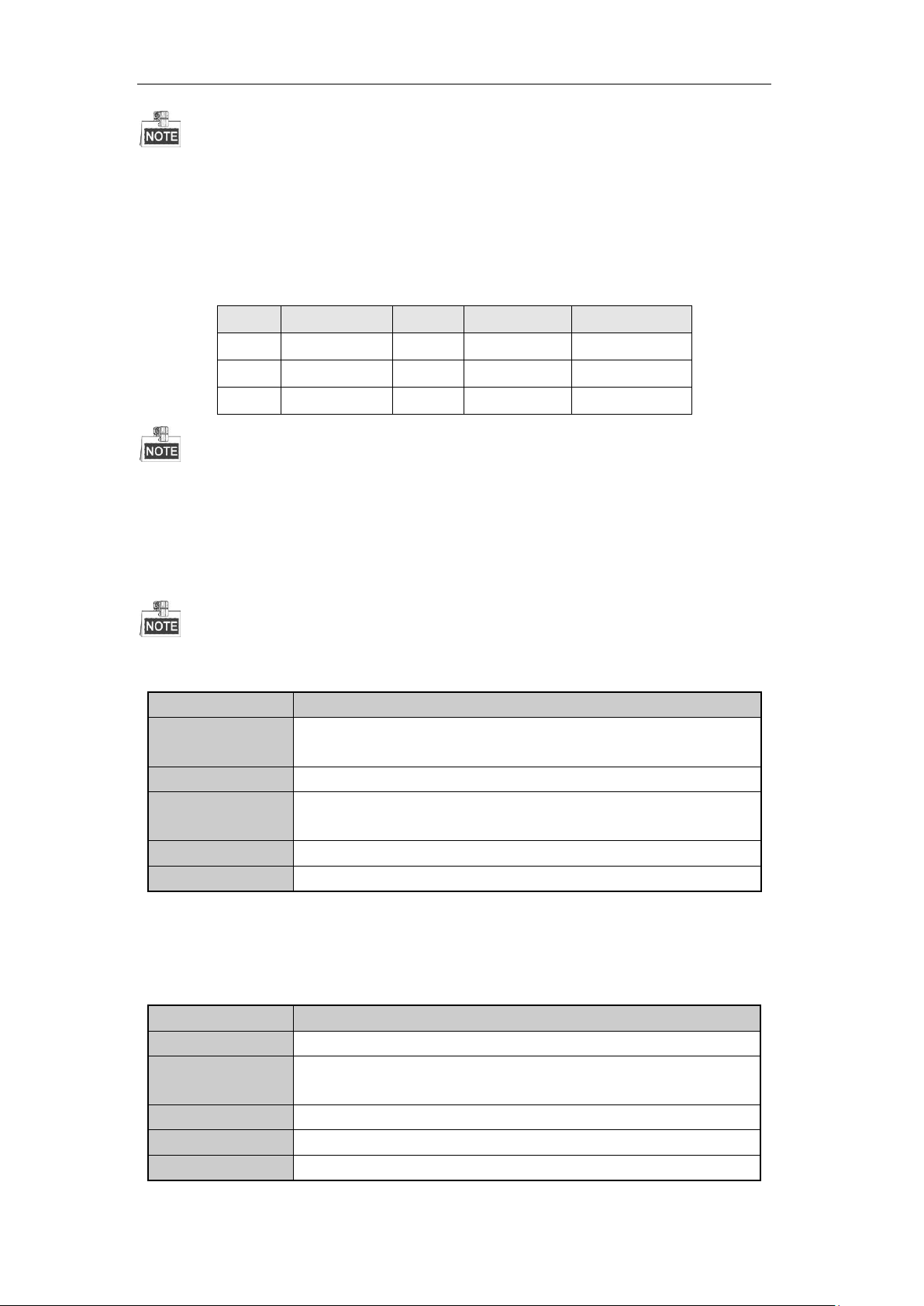
User Manual of Digital Video Recorder
S.N
VGA/HDMI
CVBS
Main output
Auxiliary output
1 √ √
VGA/HDMI
CVBS
2 √ ×
VGA/HDMI
3 × √ CVBS
Functions
Front Panel Operation
Show single screen
Press the corresponding Alphanumeric button. E.g. Press 2 to display only the
screen for channel 2.
Show multi-screen
Press the PREV button.
Manually switch
screens
Next screen: right direction button.
Previous screen: left direction button.
Auto-switch
Press Enter button.
Playback
Press Play button.
Name
Description
Menu
Enter the main menu of the system by right clicking the mouse.
Single Screen
Switch to the single full screen by choosing channel number from the dropdown
list.
Multi-screen
Adjust the screen layout by choosing from the dropdown list.
Previous Screen
Switch to the previous screen.
Next Screen
Switch to the next screen.
The √ means the interface is in use, × means the interface is out of use or the connection is invalid. And the
HDMI, VGA and CVBS can be used at the same time.
For Other Models
For the other models, the priority level for the main and aux output is HDMI/VGA>CVBS. See the table below.
Table 3. 4 Priorities of Interfaces
√ means the interface is in use, × means the interface is out of use or the connection is invalid. And the HDMI,
VGA and CVBS can be used at the same time.
3.2.1 Front Panel Operation
This function is not supported by DS-7200HGHI and DS-7100 series.
Table 3. 5 Front Panel Operation in Live View
3.2.2 Using the Mouse in Live View
Table 3. 6 Mouse Operation in Live View
55

User Manual of Digital Video Recorder
Start/Stop
Auto-switch
Enable/disable the auto-switch of the screens.
The dwell time of the live view configuration must be set before using Start Auto-switch.
Start Recording
Start recording of all channels, Normal Record and Motion Detection Recording
are selectable from the dropdown list.
Add IP Camera
A shortcut to enter the IP camera management interface.(For HDVR series only)
Quick Set
Output Mode is configurable with Standard, Bright, Gentle and Vivid options.
Playback
Enter the playback interface and start playing back the video of the selected
channel immediately.
PTZ Control
A shortcut to enter the PTZ control interface of the selected camera.
Aux Monitor
Switch to the auxiliary output mode and the operation for the main output is
disabled.
If you enter Aux monitor mode and the Aux monitor is not connected, the mouse
operation is disabled; you need to switch back to the Main output with the F1 button on front
panel or VOIP/MON button on IR remote control and then press the Enter button.
DS-7200 Series DS-7300 and DS-8100/9000 Series
Figure 3. 1 Right-click Menu
The Add IP Camera is not supported by DS-7100 series DVR.
3.2.3 Main/Aux Output Switching
The DS-7100-SH, DS-7200-SH, and DS-7324/7332HGHI-SH models do not support Aux/Main output switch.
When the HDMI, HDMI/VGA or HDMI1/VGA (DS-8124/8132HGHI-SH) output is configured as the main
output, you can perform the following operation to switch to CVBS, VGA or HDMI2 (DS-8124/8132HGHI-SH)
output as the main output.
56

User Manual of Digital Video Recorder
Icons
Description
Icons
Description
Icons
Description
/
Enable/Disable
Manual Record
Instant Playback
/
Mute/Audio on
PTZ Control
Digital Zoom
Image Settings
Live View
Strategy
Close Live View
Steps:
1. Use the mouse wheel to double-click on the HDMI (1)/VGA output screen, and the following message
box pops up:
Figure 3. 2 Switch Main and Aux Output
2. Use the mouse wheel to double-click on the screen again to switch to the Aux output, or click Cancel to
cancel the operation.
3. Select the Menu Output Mode to Main CVBS or HDMI2 from the right-click menu on the monitor.
4. On the pop-up message box, click Yes to restart the device to enable the CVBS output or HDMI2 as the
main output.
You can select the Menu Output Mode under Menu>Configuration>More Settings to Auto, or HDMI (1)/VGA
and then restart the device to switch the main output back to HDMI (1)/VGA output.
3.2.4 Quick Setting Toolbar in Live View Mode
On the screen of each channel, there is a quick setting toolbar which shows when you point the mouse to the
bottom of the screen.
Figure 3. 3 Quick Setting Toolbar
Table 3. 7 Description of Quick Setting Toolbar Icons
Instant Playback only shows the record in last five minutes. If no record is found, it means there is no
record during the last five minutes.
Digital Zoom can zoom in the selected area to the full screen. Click and draw to select the area to zoom in,
57
User Manual of Digital Video Recorder
as shown in Figure 3. 4.
Figure 3. 4 Digital Zoom
Image Settings icon can be selected to enter the Image Settings menu.
Four modes are selectable according to the real situation:
• Standard: for general lighting conditions (default).
• Indoor: the image is relatively smoother.
• Dim Light: the image is smoother than the other two modes.
• Outdoor: the image is relatively clearer and sharper. The degree of contrast and saturation is high.
Figure 3. 5 Image Settings
You can adjust the image parameters, including brightness, contrast, saturation, hue, sharpness and denoising.
You can also click Default to restore the default settings and click Copy to copy the image settings to other
analog cameras.
Refer to the Chapter 11.3 Configuring Video Parameters for details.
Live View Strategy can be selected to set strategy, including Real-time, Balanced, Fluency.
58

User Manual of Digital Video Recorder
Figure 3. 6 Live View Strategy
59

User Manual of Digital Video Recorder
3.3 Channel-zero Encoding
This chapter is not applicable to DS-7100 and DS-7200 series DVR
Purpose:
Sometimes you need to get a remote view of many channels in real time from web browser or CMS (Client
Management System) software, in order to decrease the bandwidth requirement without affecting the image
quality, channel-zero encoding is supported as an option for you.
Steps:
1. Enter the Live View Settings interface.
Menu> Configuration> Live View
2. Select the Channel-Zero Encoding tab.
Figure 3. 7 Live View- Channel-Zero Encoding
3. Check the checkbox after Enable Channel-Zero Encoding.
4. Configure the Frame Rate, Max. Bitrate Mode and Max. Bitrate.
5. Click the Apply button to activate the settings.
After you set the Channel-Zero encoding, you can get a view in the remote client or web browser of 16
channels in one screen.
60
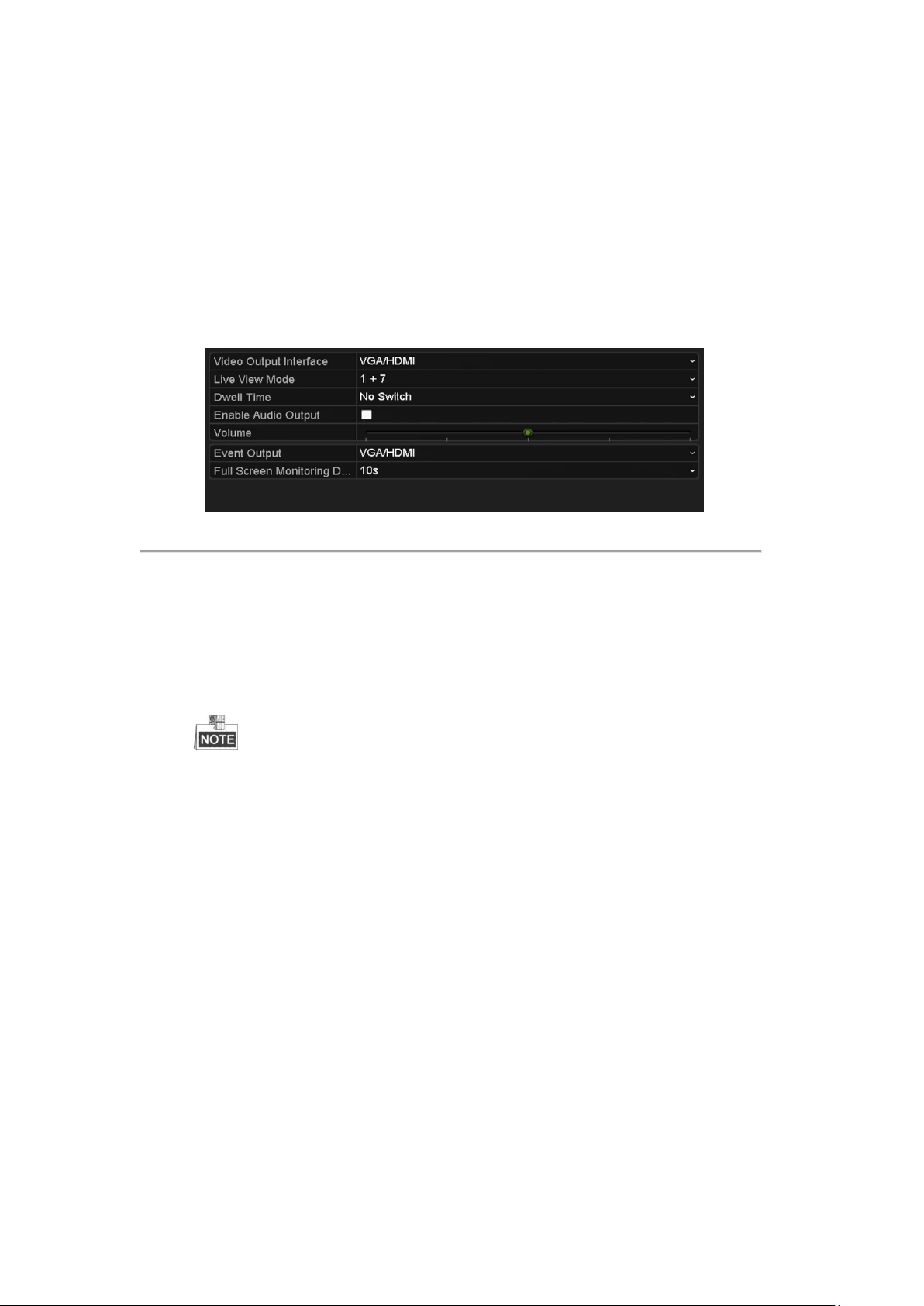
User Manual of Digital Video Recorder
3.4 Adjusting Live View Settings
Purpose:
Live View settings can be customized according to different needs. You can configure the output interface,
dwell time for screen to be shown, mute or turning on the audio, the screen number for each channel, etc.
Steps:
1. Enter the Live View Settings interface.
Menu> Configuration> Live View
Figure 3. 8 Live View-General
The settings available in this menu include:
• Video Output Interface: Designates the output to configure the settings for. The DS-7100, DS-7200,
and DS-7324/7332HGHI-SH provide HDMI/VGA outputs; DS-8124/8132HGHI-SH provides
HDMI1/VGA and HDMI2 outputs; DS-7308/7316HQHI-SH and DS-8108/8116HQHI-SH provide
HDMI, VGA and CVBS outputs; and other models provide HDMI/VGA and CVBS outputs for
selection.
The DS-7300-SH and DS-8100-SH provide the Channel-zero video output option for configuring the
parameters.
• Live View Mode: Designates the display mode to be used for Live View.
• Dwell Time: The time in seconds to dwell between switching of channels when enabling auto-switch
in Live View.
• Enable Audio Output: Enables/disables audio output for the selected camera in the live view mode.
• Volume: Adjust the volume of the audio output.
• Event Output: Designates the output to show event video; if available, you can select a different
video output interface from the Video Output Interface when an event occurs.
• Full Screen Monitoring Dwell Time: The time in seconds to show alarm event screen.
2. Set the camera order.
1) Select View tab.
61

User Manual of Digital Video Recorder
Figure 3. 9 Live View- Camera Order
2) Click a window to select it, and then double-click a camera name in the camera list you would like to
display. Setting an ‘X’ means the window will not display any camera.
3) You can also click to start live view of all channels in order and click to stop live view of all
channels. Click or to go to the previous or next page.
4) Click the Apply button.
62
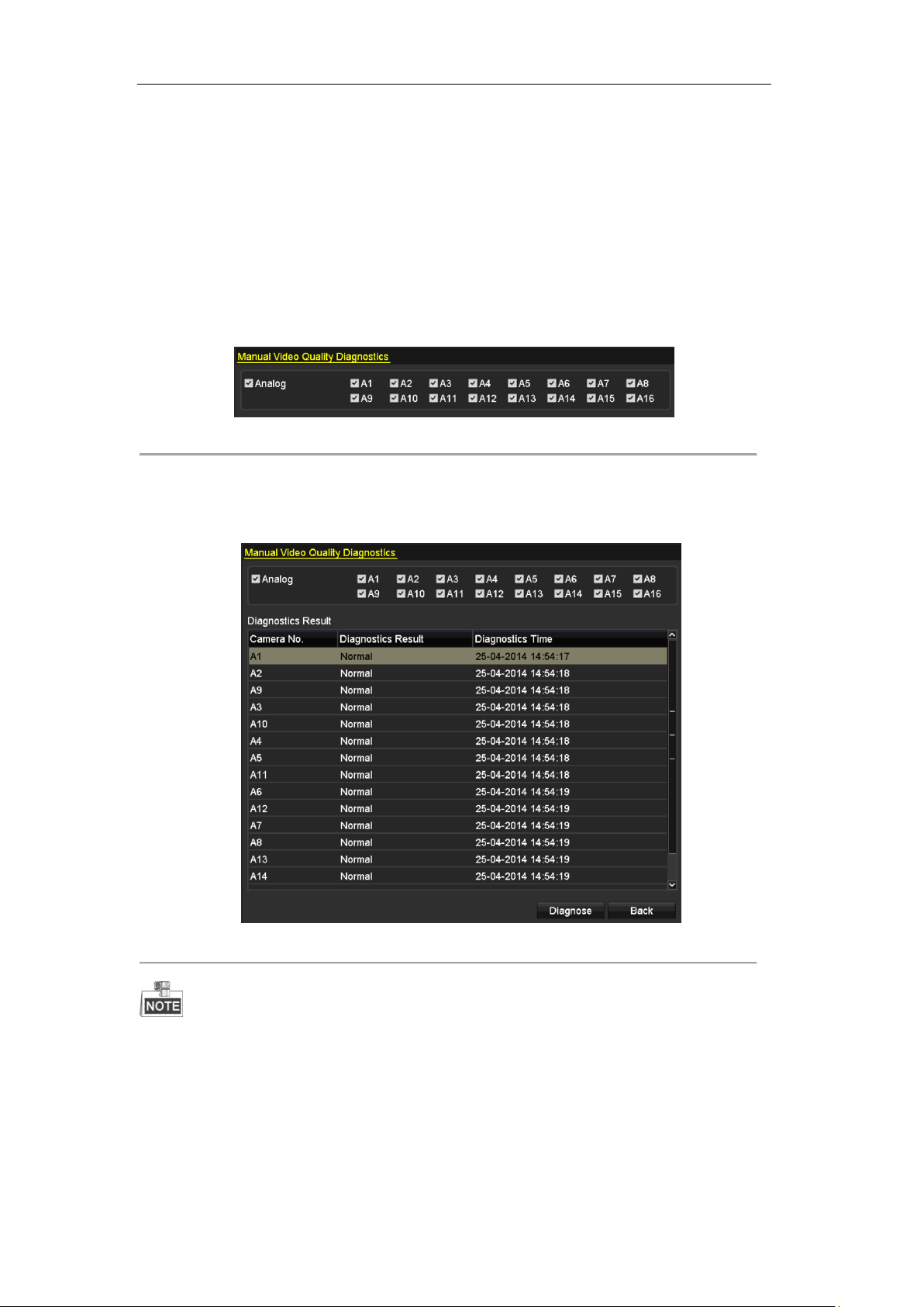
User Manual of Digital Video Recorder
3.5 Manual Video Quality Diagnostics
Purpose:
The video quality of the analog channels can be diagnosed manually and you can view the diagnostic results
from a list.
Steps:
1. Enter the Manual Video Quality Diagnostics interface.
Menu> Manual >Manual Video Quality Diagnostics
Figure 3. 10 Video Quality Diagnostics
2. Check the checkboxes to select the channels for diagnostics.
3. Click the button Diagnose, and the results will be displayed on a list. You can view the video status and
diagnostics time of the selected channels.
Figure 3. 11 Diagnostics Result
Connect the camera to the device for the video quality diagnostics.
Three exception types can be diagnosed: Blurred Image, Abnormal Brightness and Color Cast.
63

User Manual of Digital Video Recorder
3.6 User Logout
Purpose:
After logging out, the monitor turns to the live view mode and if you want to do some operation, you need to
enter user name and password to log in again.
Steps:
3. Enter the Shutdown menu.
Menu>Shutdown
4. Click Logout.
Figure 3. 12 Shutdown
64

User Manual of Digital Video Recorder
Chapter 4 PTZ Controls
65
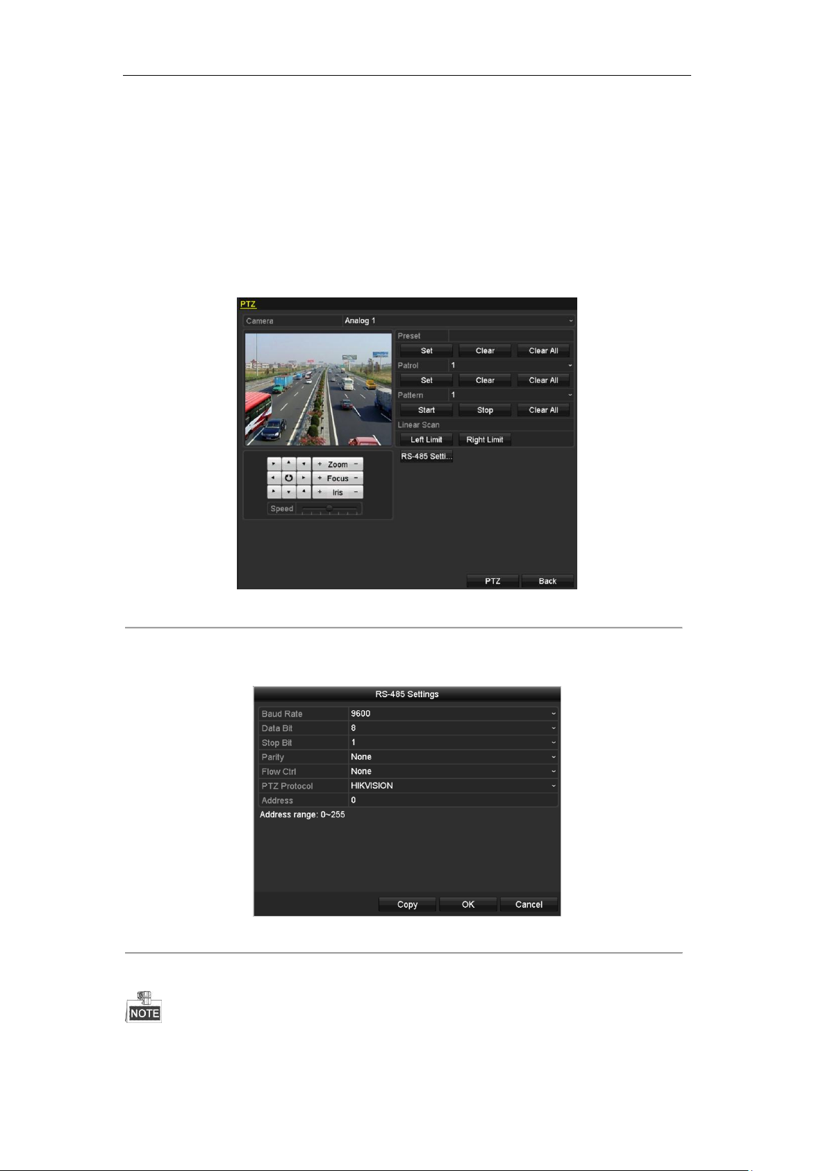
User Manual of Digital Video Recorder
4.1 Configuring PTZ Settings
Purpose:
Follow the procedure to set the parameters for PTZ. The configuring of the PTZ parameters should be done
before you control the PTZ camera.
Steps:
1. Enter the PTZ Settings interface.
Menu >Camera> PTZ
Figure 4. 1 PTZ Settings
2. Choose the camera for PTZ setting in the Camera dropdown list.
3. Click the RS-485 Settings button to set the RS-485 parameters.
Figure 4. 2 PTZ- General
4. Enter the parameters of the PTZ camera.
All the parameters should be exactly the same as the PTZ camera parameters.
66

User Manual of Digital Video Recorder
For the Coaxitron camera/dome connected, you can select the PTZ protocol to HIKVISION-C (Coaxitron).
Make sure the protocol selected here is supported by the connected camera/dome.
When the Coaxitron protocol is selected, all the other parameters like the baud rate, data bit, stop bit, parity and
flow control are not configurable.
5. Click Apply button to save the settings.
67

User Manual of Digital Video Recorder
4.2 Setting PTZ Presets, Patrols & Patterns
Before you start:
Please make sure that the presets, patrols and patterns should be supported by PTZ protocols.
4.2.1 Customizing Presets
Purpose:
Follow the steps to set the Preset location which you want the PTZ camera to point to when an event takes
place.
Steps:
1. Enter the PTZ Control interface.
Menu>Camera>PTZ
Figure 4. 3 PTZ Settings
2. Use the directional button to wheel the camera to the location where you want to set preset; and the zoom
and focus operations can be recorded in the preset as well.
3. Enter the preset No. (1~255) in the preset text field, and click the Set button to link the location to the
preset.
Repeat the steps2-3 to save more presets.
You can click the Clear button to clear the location information of the preset, or click the Clear All button
to clear the location information of all the presets.
4.2.2 Calling Presets
Purpose:
This feature enables the camera to point to a specified position such as a window when an event takes place.
Steps:
68
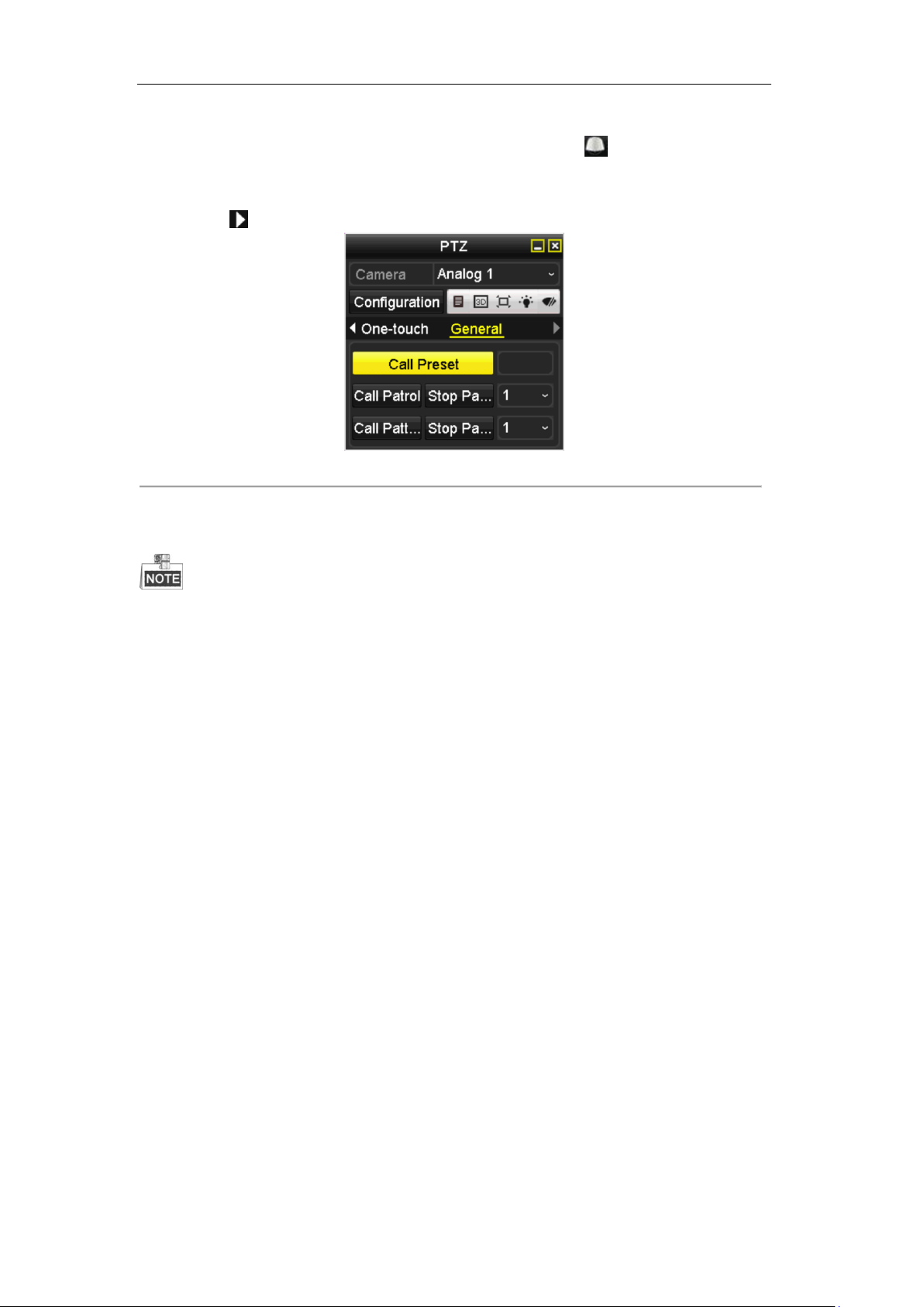
User Manual of Digital Video Recorder
1. Click the button PTZ in the lower-right corner of the PTZ setting interface;
Or press the PTZ button on the front panel or click the PTZ Control icon in the quick setting bar, or
select the PTZ option in the right-click menu to show the PTZ control panel.
2. Choose Camera in the dropdown list.
3. Click the button to show the general settings of the PTZ control.
Figure 4. 4 PTZ Panel - General
4. Click to enter the preset No. in the corresponding text field.
5. Click the Call Preset button to call it.
When the Coaxitron camera/dome connected and the PTZ protocol is selected to HIKVISION-C
(Coaxitron), you can call the preset 95 to enter the menu of the connected Coaxitron camera/dome. Use the
directional buttons on the PTZ control panel to operate the menu.
4.2.3 Customizing Patrols
Purpose:
Patrols can be set to move the PTZ to different key points and have it stay there for a set duration before moving
on to the next key point. The key points are corresponding to the presets. The presets can be set following the
steps above in Customizing Presets.
Steps:
1. Enter the PTZ Control interface.
Menu>Camera>PTZ
69
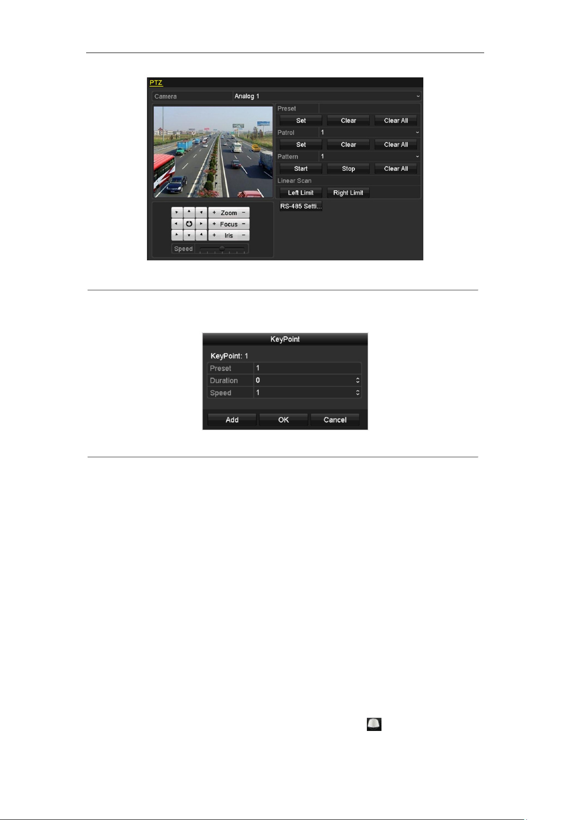
User Manual of Digital Video Recorder
Figure 4. 5 PTZ Settings
2. Select patrol No. in the drop-down list of patrol.
3. Click the Set button to add key points for the patrol.
Figure 4. 6 Key point Configuration
4. Configure key point parameters, such as the key point No., duration of staying for one key point and speed
of patrol. The key point is corresponding to the preset. The Key Point No. determines the order at which
the PTZ will follow while cycling through the patrol. The Duration refers to the time span to stay at the
corresponding key point. The Speed defines the speed at which the PTZ will move from one key point to
the next.
5. Click the Add button to add the next key point to the patrol, or you can click the OK button to save the
key point to the patrol.
You can delete all the key points by clicking the Clear button for the selected patrol, or click the Clear
All button to delete all the key pints for all patrols.
4.2.4 Calling Patrols
Purpose:
Calling a patrol makes the PTZ to move according the predefined patrol path.
Steps:
1. Click the button PTZ in the lower-right corner of the PTZ setting interface;
Or press the PTZ button on the front panel or click the PTZ Control icon in the quick setting bar, or
select the PTZ option in the right-click menu to show the PTZ control panel.
70
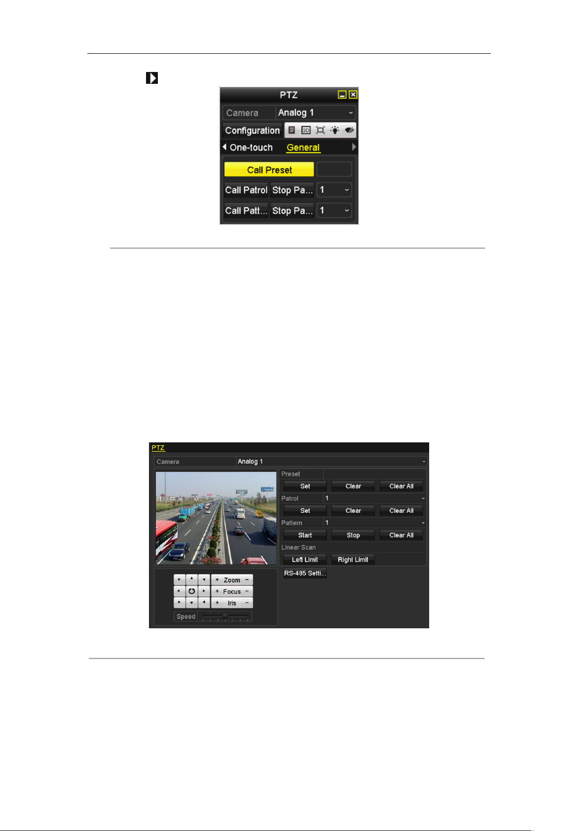
User Manual of Digital Video Recorder
2. Click the button to show the general settings of the PTZ control.
Figure 4. 7 PTZ Panel - General
3. Select a patrol in the dropdown list and click the Call Patrol button to call it.
4. You can click the Stop Patrol button to stop calling it.
4.2.5 Customizing Patterns
Purpose:
Patterns can be set by recording the movement of the PTZ. You can call the pattern to make the PTZ movement
according to the predefined path.
Steps:
1. Enter the PTZ Control interface.
Menu > Camera > PTZ
Figure 4. 8 PTZ Settings
2. Choose pattern number in the dropdown list.
3. Click the Start button and click corresponding buttons in the control panel to move the PTZ camera, and
click the Stop button to stop it.
The movement of the PTZ is recorded as the pattern.
71

User Manual of Digital Video Recorder
4.2.6 Calling Patterns
Purpose:
Follow the procedure to move the PTZ camera according to the predefined patterns.
Steps:
1. Click the button PTZ in the lower-right corner of the PTZ setting interface;
Or press the PTZ button on the front panel or click the PTZ Control icon in the quick setting bar, or
select the PTZ option in the right-click menu to show the PTZ control panel.
2. Click the button to show the general settings of the PTZ control.
Figure 4. 9 PTZ Panel - General
3. Click the Call Pattern button to call it.
4. Click the Stop Pattern button to stop calling it.
4.2.7 Customizing Linear Scan Limit
Purpose:
The Linear Scan can be enabled to trigger the scan in the horizantal direction in the predefined range.
This function is supported by some certain models.
Steps:
1. Enter the PTZ Control interface.
Menu > Camera > PTZ
72

User Manual of Digital Video Recorder
Figure 4. 10 PTZ Settings
2. Use the directional button to wheel the camera to the location where you want to set the limit, and click
the Left Limit or Right Limit button to link the location to the corresponding limit.
The speed dome starts linear scan from the left limit to the right limit, and you must set the left limit on the left
side of the right limit, as well the angle from the left limit to the right limit should be no more than 180º.
4.2.8 Calling Linear Scan
Purpose:
Follow the procedure to call the linear scan in the predefined scan range.
Steps:
1. Click the button PTZ in the lower-right corner of the PTZ setting interface;
Or press the PTZ button on the front panel or click the PTZ Control icon in the quick setting bar to
enter the PTZ setting menu in live view mode.
2. Click the button to show the one-touch function of the PTZ control.
Figure 4. 11 PTZ Panel - One-touch
3. Click Linear Scan button to start the linear scan and click the Linear Scan button again to stop it.
You can click the Restore button to clear the defined left limit and right limit data and the dome needs to
73

User Manual of Digital Video Recorder
reboot to make settings take effect.
4.2.9 One-touch Park
Purpose:
For some certain model of the speed dome, it can be configured to start a predefined park action (scan, preset,
patrol and etc.) automatically after a period of inactivity (park time).
Steps:
1. Click the button PTZ in the lower-right corner of the PTZ setting interface;
Or press the PTZ button on the front panel or click the PTZ Control icon in the quick setting bar to
enter the PTZ setting menu in live view mode.
2. Click the button to show the one-touch function of the PTZ control.
Figure 4. 12 PTZ Panel - One-touch
3. There are 3 one-touch park types selectable, click the corresponding button to activate the park action.
Park (Quick Patrol): The dome starts patrol from the predefined preset 1 to preset 32 in order after the
park time. The undefined preset will be skipped.
Park (Patrol 1): The dome starts move according to the predefined patrol 1 path after the park time.
Park (Preset 1): The dome moves to the predefined preset 1 location after the park time.
The park time can only be set through the speed dome configuration interface, by default the value is
5s.
4. Click the button again to inactivate it.
74

User Manual of Digital Video Recorder
Icon
Description
Icon
Description
Icon
Description
Direction button and
the auto-cycle button
Zoom+, Focus+,
Iris+
Zoom-, Focus-, Iris-
The speed of the
PTZ movement
Light on/off
Wiper on/off
3D-Zoom
Image Centralization
Menu
Switch to the PTZ
control interface
Switch to the
one-touch control
interface
Switch to the general
settings interface
Previous item
Next item
Start pattern / patrol
Stop the patrol /
pattern movement
Exit
Minimize windows
4.3 PTZ Control Panel
To enter the PTZ control panel, there are two ways supported.
OPTION 1:
In the PTZ settings interface, click the PTZ button on the lower-right corner which is next to the Back button.
OPTION 2:
In the Live View mode, you can press the PTZ Control button on the front panel or on the remote control, or
choose the PTZ Control icon , or select the PTZ option in the right-click menu.
Click the Configuration button on the control panel, and you can enter the PTZ Settings interface.
In PTZ control mode, the PTZ panel will be displayed when a mouse is connected with the device. If no
mouse is connected, the icon appears in the lower-left corner of the window, indicating that this
camera is in PTZ control mode.
Figure 4. 13 PTZ Panel
Table 4. 1 Description of the PTZ panel icons
75

User Manual of Digital Video Recorder
Chapter 5 Recording Settings
76

User Manual of Digital Video Recorder
5.1 Configuring Recording Parameters
Before you start:
1. Make sure that the HDD has already been installed. If not, please install a HDD and initialize it.
(Menu>HDD>General)
Figure 5. 1 HDD- General
2. Click Advance to check the storage mode of the HDD.
1) Whether the HDD mode is Quota, please set the maximum record capacity. For detailed information,
see Chapter 10.5 Configuring Quota Mode.
2) If the HDD mode is Group, you should set the HDD group. For detailed information, see Chapter 5.9
Configuring HDD Group for Recording.
Figure 5. 2 HDD- Advanced
Steps:
1. Enter the Record settings interface to configure the encoding parameters:
Menu>Record>Parameters
Figure 5. 3 Record Parameters
2. Set the parameters for recording.
77

User Manual of Digital Video Recorder
1) Select the Record tab to configure.
2) Select a camera number in the camera dropdown list.
You can configure the stream type, the resolution, the video quality and other parameters on demand
for Main Stream (Continuous) and Main Stream (Event) respectively.
The Input Resolution of camera connected will be displayed in the live view for 5 seconds when the
camera is connected, or the DVR is powered on. The input resolution includes the resolution and
frame rate of the camera, e.g. 1080P25.
3) You can configure the advantage parameters, including pre-record, post-record time, expired time,
redundant record (this option is only available when the HDD mode is Group) and whether you want
to record audio.
• Pre-record: The time you set to record before the scheduled time or event. For example, when an
alarm triggered the recording at 10:00, if you set the pre-record time as 5 seconds, the camera
records it at 9:59:55.
• Post-record: The time you set to record after the event or the scheduled time. For example, when
an alarm triggered the recording ends at 11:00, if you set the post-record time as 5 seconds, it
records till 11:00:05.
• Expired Time: The expired time is the longest time for a record file to be kept in the HDD, if the
deadline is reached, the file will be deleted. You can set the expired time to 0, and then the file will
not be deleted. The actual keeping time for the file should be determined by the capacity of the
HDD.
• Redundant Record: The redundant record is to decide whether you want the camera to save the
record files in the redundant HDD. You must configure the redundant HDD in HDD settings. For
detailed information, see Chapter 5.8 Configuring Redundant Recording.
• Record Audio: Check the checkbox of Record Audio to record the sound, otherwise record the
image without sound.
• Video Stream: Main stream and sub-stream are selectable for recording. When you select
sub-stream, you can record for a longer time with the same storage space.
• Enable 960 Mode: The option is supported by analog cameras. Enabling the 960 mode to enable
the WD1 resolution for the main stream, otherwise, the resolution supports up to 4CIF. And the
option does not supported by TVI cameras, while the WD1 resolution is available all the time.
4) Click Apply to save the settings.
5) You can copy the settings to other channels by clicking Copy, if the setting can also be used for other
cameras.
You can copy the same settings to the cameras with same signal, e.g., the channel No. 1-3 connect to the TVI
cameras, and the channel No.4 connects to an analog camera, and then the settings of channel No. 1 can be only
copied to channel 2 and 3.
78

User Manual of Digital Video Recorder
Figure 5. 4 Copy Camera Settings
3. Set encoding parameters for sub-stream.
1) Select the Substream tab.
Figure 5. 5 Sub-stream Encoding
2) Select a camera in the camera dropdown list.
3) Configure the parameters.
4) Click Apply to save the settings.
5) (Optional) If the parameters can also be used to other cameras, click Copy to copy the settings to other
channels.
79
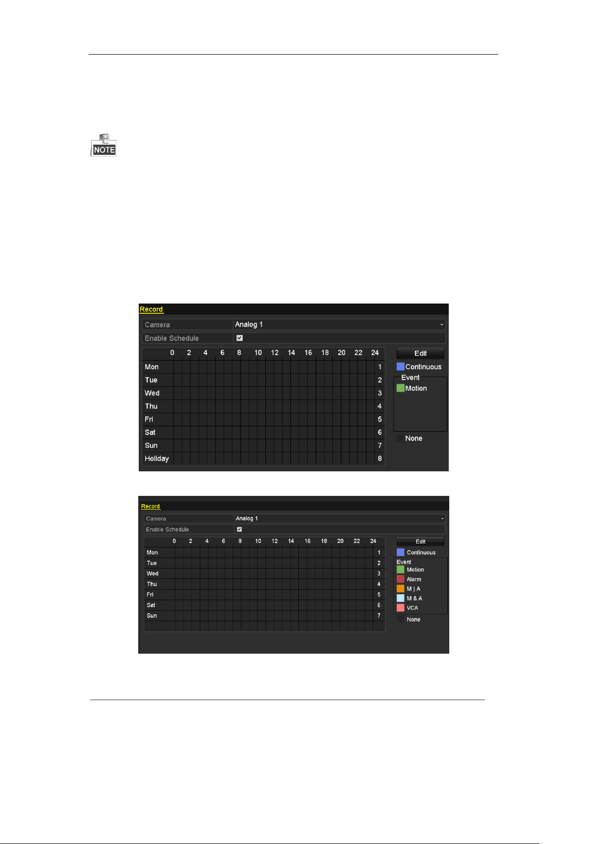
User Manual of Digital Video Recorder
5.2 Configuring Record Schedule
The DS-7100 models support the continuous and motion triggered recording only, DS-7200HGHI models
support continuous, motion and VCA triggered recording types, and other models support continuous, alarm,
motion, motion | alarm, motion & alarm and VCA triggered recording types.
Purpose:
Set the record schedule, and then the camera will automatically start/stop recording according to the configured
schedule.
Steps:
1. Enter the Record Schedule interface.
Menu> Record> Schedule
DS-7100-SH and DS-7200HGHI-SH
Other Models
Figure 5. 6 Record Schedule
2. Choose the camera you want to configure in the Camera dropdown list.
3. Check the checkbox of Enable Schedule.
4. Configure the record schedule.
Edit the schedule
80

User Manual of Digital Video Recorder
1) Click Edit.
2) In the message box, you can choose the day to which you want to set schedule.
3) To schedule an all-day recording, check the checkbox after the All Day item.
Figure 5. 7 Edit Schedule- All Day
4) To arrange other schedule, leave the All Day checkbox blank and set the Start/End time.
Figure 5. 8 Edit Schedule- Set Time Period
Up to 8 periods can be configured for each day. And the time periods cannot be overlapped with each other.
Repeat the above steps 1)-4) to schedule recording for other days in the week. If the schedule can also be
set to other days, click Copy.
Figure 5. 9 Copy Schedule to Other Days
The Holiday option is available when you enable holiday schedule in Holiday settings. See Chapter 5.7
Configuring Holiday Record.
5) Click OK to save setting and back to upper level menu.
81
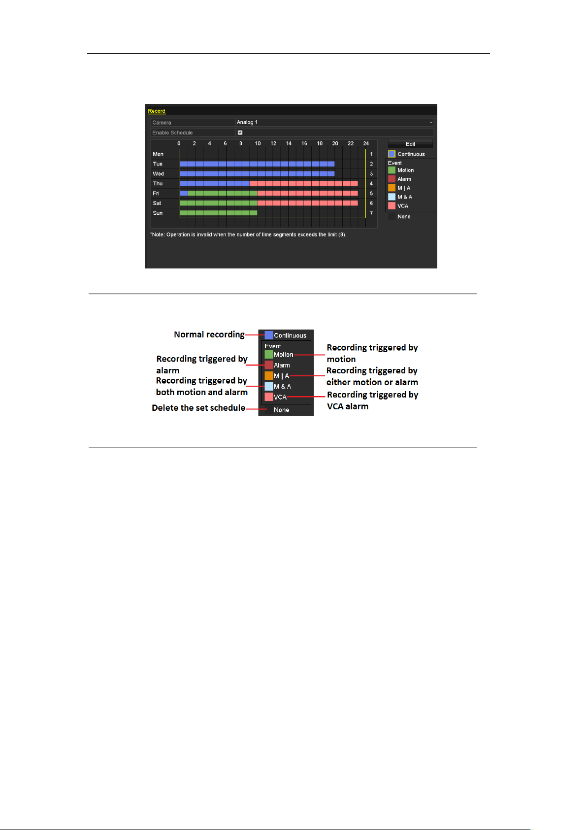
User Manual of Digital Video Recorder
Draw the schedule
1) Click on the color icon to select a record type in the event list on the right-side of the interface.
Figure 5. 10 Draw the Schedule
Descriptions of the color icons are shown in the figure below.
Figure 5. 11 Descriptions of the Color Icons
2) Click and drag the mouse on the schedule.
3) Click on the other area except for the schedule table to finish and exit the drawing.
You can repeat step 4 to set schedule for other channels. If the settings can also be used to other channels,
click Copy, and then choose the channel to which you want to copy.
5. Click Apply in the Record Schedule interface to save the settings.
82

User Manual of Digital Video Recorder
5.3 Configuring Motion Detection Record
Purpose:
Follow the steps to set the motion detection parameters. In the live view mode, once a motion detection event
takes place, the DVR can analyze it and do many actions to handle it. Enabling motion detection function can
trigger certain channels to start recording, or trigger full screen monitoring, audio warning, notifying the
surveillance center, sending email and so on.
Steps:
1. Enter the Motion Detection interface.
Menu>Camera>Motion
Figure 5. 12 Motion Detection
2. Configure Motion Detection:
1) Choose camera you want to configure.
2) Check the checkbox after Enable Motion Detection.
3) Drag and draw the area for motion detection by mouse. If you want to set the motion detection for all
the area shot by the camera, click Full Screen. To clear the motion detection area, click Clear.
Figure 5. 13 Motion Detection- Mask
4) Click Handling, and the message box for channel information pops up.
83

User Manual of Digital Video Recorder
Figure 5. 14 Motion Detection Settings
5) Select the channels which you want the motion detection event to trigger recording.
6) Click Apply to save the settings.
7) Click OK to back to the upper level menu.
8) Exit the Motion Detection menu.
3. Configure the schedule.
Please refer to the step 4 of Chapter 5.2 Configuring Record Schedule, while you may choose Motion as
the record type.
84
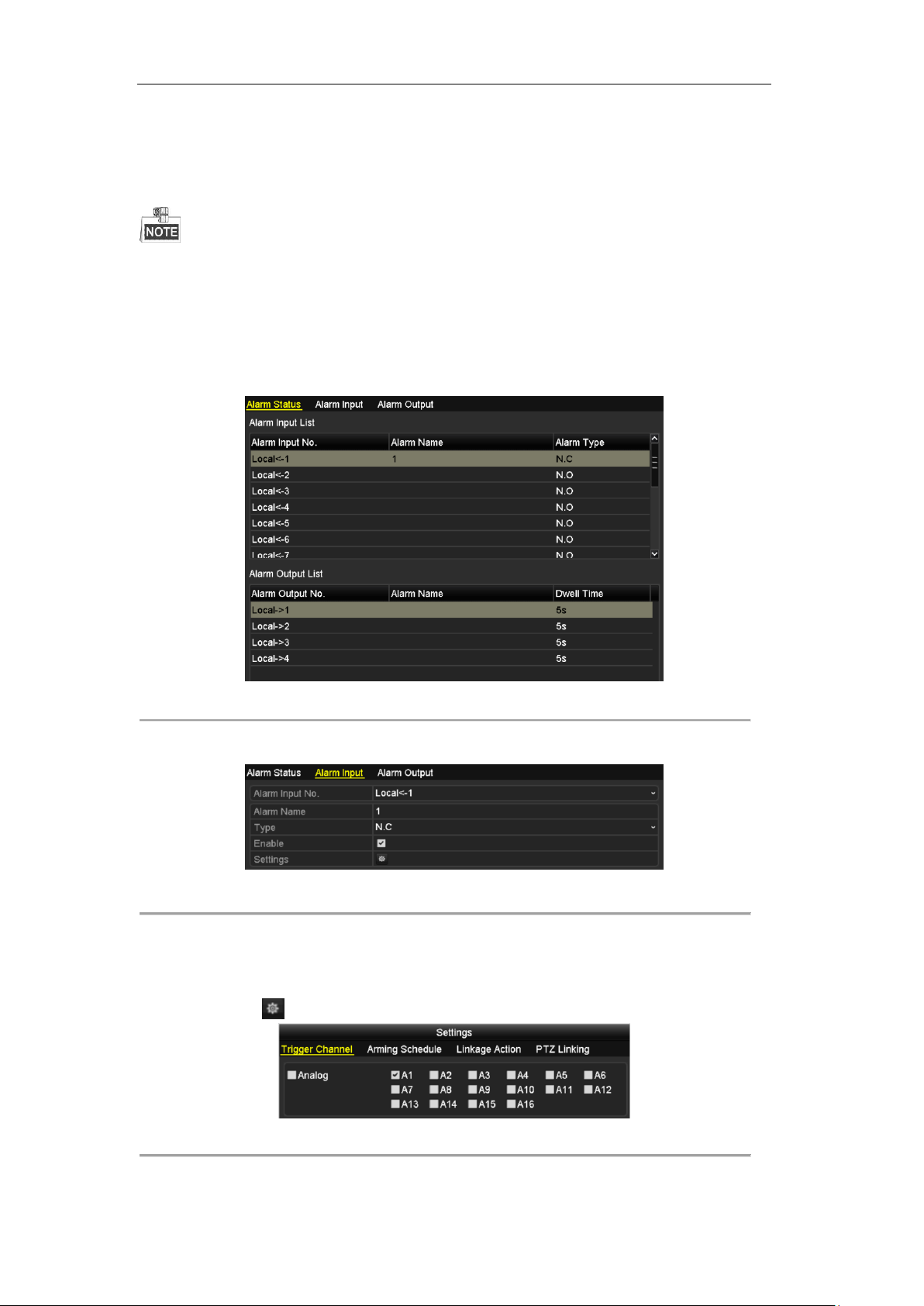
User Manual of Digital Video Recorder
5.4 Configuring Alarm Triggered Record
The DS-7100 and DS-7200 series do not support the alarm input.
Purpose:
Follow the procedure to configure alarm triggered recording.
Steps:
1. Enter the Alarm setting interface.
Menu> Configuration> Alarm
Figure 5. 15 Alarm Settings
2. Click the Alarm Input tab.
Figure 5. 16 Alarm Settings- Alarm Input
1) Select Alarm Input number and configure alarm parameters.
2) Choose N.O (normally open) or N.C (normally closed) for alarm type.
3) Check the checkbox of Setting.
4) Click the button.
Figure 5. 17 Alarm Handling
5) Choose the alarm triggered recording channel.
85

User Manual of Digital Video Recorder
6) Check the checkbox to select channel.
7) Click Apply to save settings.
8) Click OK to back to the upper level menu.
Repeat the above steps to configure other alarm input parameters.
If the setting can also be applied to other alarm inputs, click Copy and choose the alarm input number.
Figure 5. 18 Copy Alarm Input
3. Configure the schedule.
Please refer to the step 4 of Chapter 5.2 Configuring Record Schedule, while you may choose Alarm as
the record type.
86

User Manual of Digital Video Recorder
5.5 Configuring VCA Record
Purpose:
The DS-7200/7300/8100/9000 support the VCA (line crossing detection and intrusion detection) triggered
recording.
The VCA settings and VCA event triggered recording is supported by 1 analog camera for
DS-7200/7300/8100HGHI models and 2 analog camers for DS-7200/7300/8100/9000HQHI models.
DS-7100-SH does not support VCA.
Steps:
1. Enter the VCA settings interface and select a camera for the VCA settings.
Menu> Camera> VCA
Figure 5. 19 VCA Settings
2. Configure the detection rules for VCA events. For details, see the step 2 in Chapter 8.5 Detecting VCA
Alarm.
3. Click the icon to configure the alarm linkage actions for the VCA events.
Select Trigger Channel tab and select one or more channels which will start to record when VCA alarm
is triggered.
Click Apply to save the settings
87
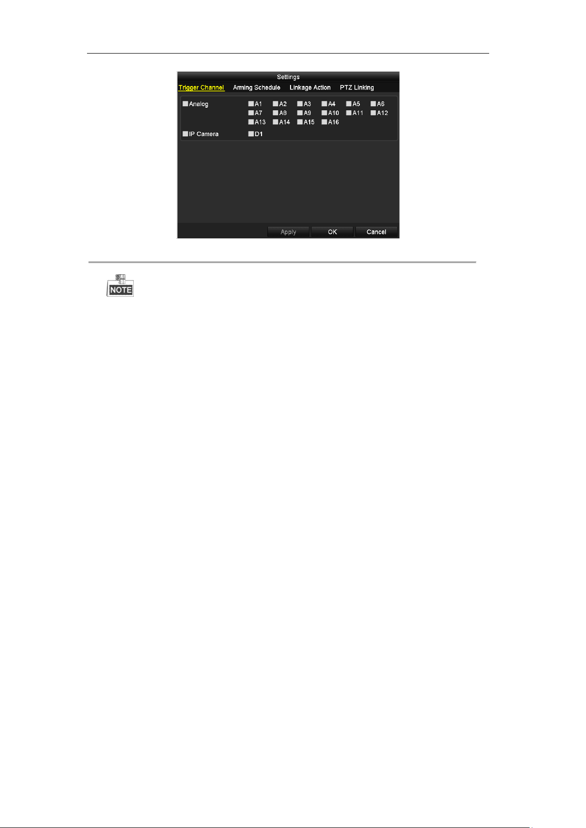
User Manual of Digital Video Recorder
Figure 5. 20 Set Trigger Camera of VCA Alarm
The PTZ Linking function is only available for the VCA settings of IP cameras.
4. Enter Record Schedule settings interface (Menu> Record> Schedule>Record Schedule), and then set VCA
as the record type. For details, see step 2 in Chapter 5.2 Configuring Record Schedule.
88

User Manual of Digital Video Recorder
5.6 Configuring Manual Record
Purpose:
Follow the steps to set parameters for the manual record. Using manual record, you don’t need to set a schedule
for recording.
Steps:
1. Enter the Manual settings interface.
Menu> Manual
Figure 5. 21 Manual Record
2. Enable manual record.
Click the status icon before camera number to change it to .
Or click the status icon of Analog to enable manual record of all channels.
3. Disable manual record.
Click the status icon to change it to .
Or click the status icon of Analog to disable manual record of all channels.
After rebooting all the manual records enabled are canceled.
89

User Manual of Digital Video Recorder
5.7 Configuring Holiday Record
Purpose:
Follow the steps to configure the record schedule on holiday for that year. You may want to have different plan
for recording on holiday.
Steps:
1. Enter the Record setting interface.
Menu>Record
2. Choose Holiday on the left bar.
Figure 5. 22 Holiday Settings
3. Enable Edit Holiday schedule.
1) Click to enter the Edit interface.
Figure 5. 23 Edit Holiday Settings
2) Check the checkbox of Enable.
3) Select Mode from the dropdown list.
There are three different modes for the date format to configure holiday schedule. By Month, By Week,
and By Month are selectable.
4) Set the start and end date.
5) Click Apply to save settings.
6) Click OK to exit the Edit interface.
90

User Manual of Digital Video Recorder
4. Configure the record schedule.
Please refer to the Chapter 5.2 Configuring Record Schedule, while you may choose Holiday in the
Schedule dropdown list, or you can draw the schedule on the timeline of Holiday.
Figure 5. 24 Edit Schedule- Holiday
Up to 8 periods can be configured for each day. And the time periods cannot be overlapped each other.
In the time table of the channel, both holiday schedule and normal day schedule are displayed.
Repeat the above step 4 to set Holiday schedule for other channel. If the holiday schedule can also be used to
other channels, click Copy and choose the channel you want to apply the settings.
91

User Manual of Digital Video Recorder
5.8 Configuring Redundant Recording
Purpose:
Enabling redundant recording, which means saving the record files not only in the R/W HDD but also in the
redundant HDD, will effectively enhance the data safety and reliability.
Before you start:
You must set the Storage mode in the HDD advanced settings to Group before you set the HDD property to
Redundant. For detailed information, please refer to Chapter 10.4 Managing HDD Group. There should be at
least another HDD which is in Read/Write status.
Steps:
1. Enter HDD Information interface.
Menu> HDD
Figure 5. 25 HDD General
2. Select the HDD and click to enter the Local HDD Settings interface.
1) Set the HDD property to Redundant.
Figure 5. 26 HDD General-Editing
2) Click Apply to save the settings.
3) Click OK to back to the upper level menu.
3. Enter the Record setting interface.
Menu> Record> Parameters
1) Select the Record tab.
92

User Manual of Digital Video Recorder
Figure 5. 27 Encoding Parameters
2) Select Camera you want to configure.
3) Check the checkbox of Redundant Record.
4) Click Apply to save settings.
If the encoding parameters can also be used to other channels, click Copy and choose the channel you want to
apply the settings.
93

User Manual of Digital Video Recorder
5.9 Configuring HDD Group for Recording
Purpose:
You can group the HDDs and save the record files in certain HDD group.
Steps:
1. Enter HDD setting interface.
Menu>HDD>Advanced
2. Select Advanced on the left bar.
Check whether the storage mode of the HDD is Group. If not, set it to Group. For detailed information,
please refer to Chapter 10.4 Managing HDD Group.
3. Select General in the left bar.
Click to enter editing interface.
4. Configuring HDD group.
1) Choose a group number for the HDD group.
2) Click Apply to save your settings.
3) Click OK to back to the upper level menu.
Repeat the above steps to configure more HDD groups.
5. Choose the Channels which you want to save the record files in the HDD group.
1) Select Advanced on the left bar.
Figure 5. 28 HDD Advanced
2) Choose Group number in the dropdown list of Record on HDD Group
3) Check the channels you want to save in this group.
4) Click Apply to save settings.
After you have configured the HDD groups, you can configure the Recording settings following the procedure
provided in Chapter 5.2-5.7.
94
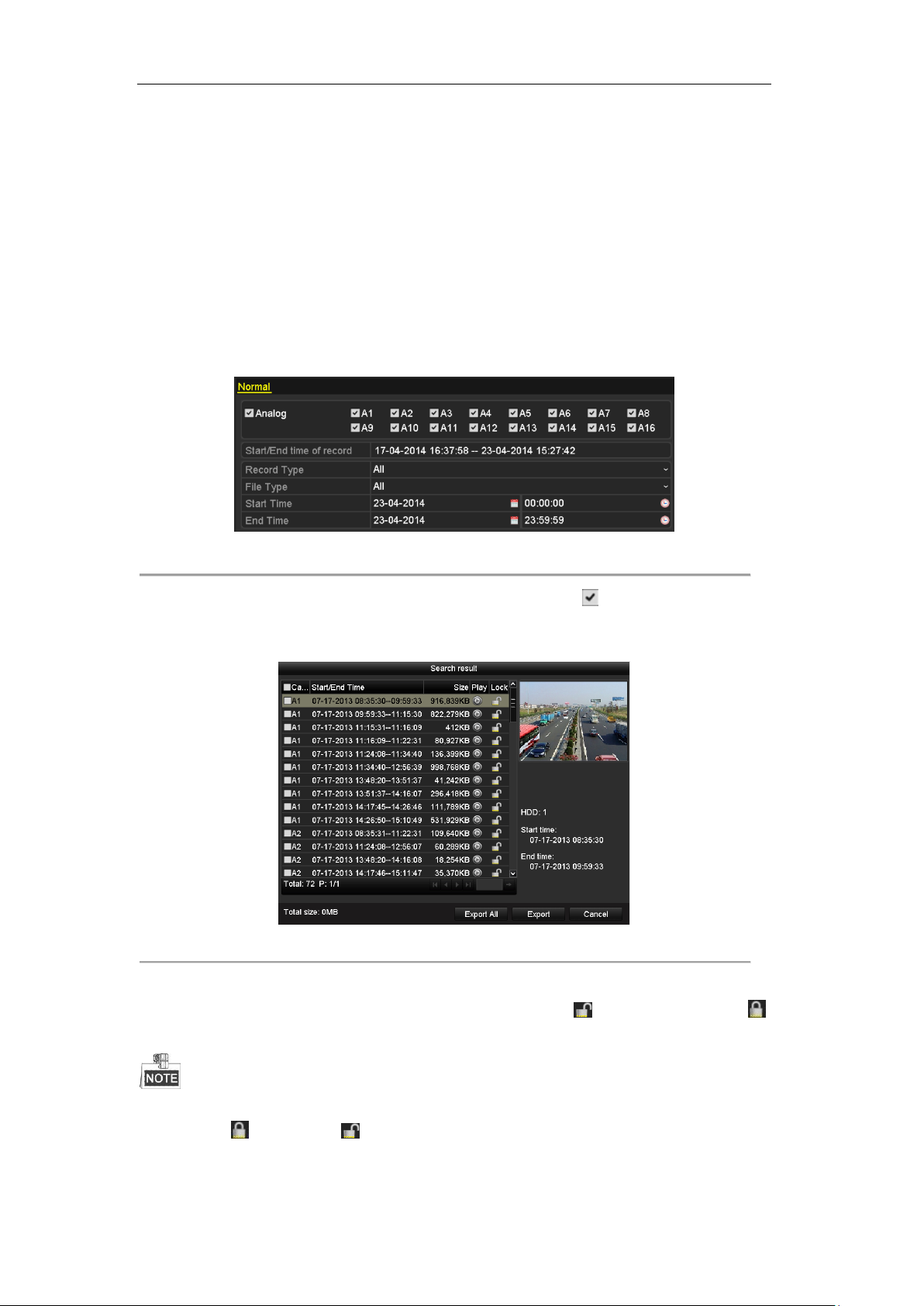
User Manual of Digital Video Recorder
5.10 Files Protection
Purpose:
You can lock the recorded files or set the HDD property to Read-only to protect the record files from being
overwritten.
Protect file by locking the record files
Steps:
1. Enter Playback setting interface.
Menu> Export
Figure 5. 29 Export
2. Select the channels you want to investigate by checking the checkbox to .
3. Configure the record type, file type, start time and end time.
4. Click Search to show the results.
Figure 5. 30 Export- Search Result
5. Protect the record files.
1) Find the record files you want to protect, and then click the icon which will turn to ,
indicating that the file is locked.
The record files of which the recording is still not completed cannot be locked.
2) Click to change it to to unlock the file and the file is not protected.
Protect file by setting HDD property to Read-only
Before you start:
95
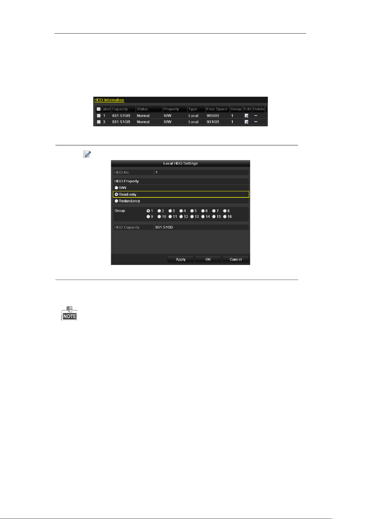
User Manual of Digital Video Recorder
To edit HDD property, you need to set the storage mode of the HDD to Group. See Chapter 10.4 Managing
HDD Group.
Steps:
1. Enter HDD setting interface.
Menu> HDD
Figure 5. 31 HDD General
2. Click to edit the HDD you want to protect.
Figure 5. 32 HDD General- Editing
3. Set the HDD to Read-only.
4. Click OK to save settings and back to the upper level menu.
You cannot save any files in a Read-only HDD. If you want to save files in the HDD, change the
property to R/W.
If there is only one HDD and is set to Read-only, the DVR cannot record any files. Only live view mode
is available.
If you set the HDD to Read-only when the DVR is saving files in it, then the file will be saved in next
R/W HDD. If there is only one HDD, the recording will be stopped.
96

User Manual of Digital Video Recorder
Chapter 6 Playback
97
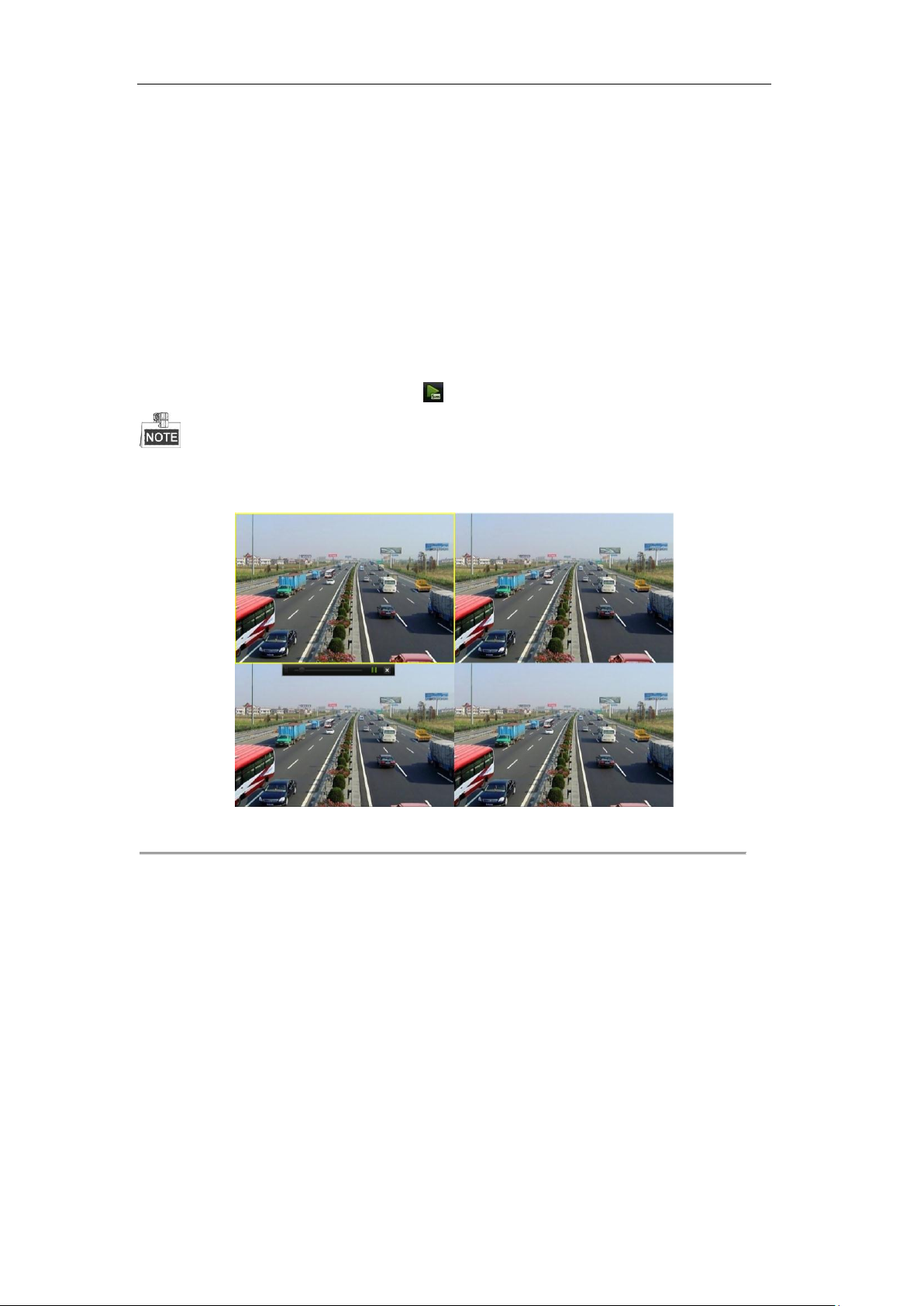
User Manual of Digital Video Recorder
6.1 Playing Back Record Files
6.1.1 Instant Playback
Purpose:
Play back the recorded video files of a specific channel in the live view mode. Channel switch is supported.
Instant playback by channel
Steps:
Choose a channel in live view mode and click the button in the quick setting toolbar.
In the instant playback mode, only record files recorded during the last five minutes on this channel will be
played back.
Figure 6. 1 Instant Playback Interface
6.1.2 Playing Back by Normal Search
Playback by Channel
Enter the Playback interface.
Mouse: right click a channel in live view mode and select Playback from the menu, as shown in the following
figure:
98
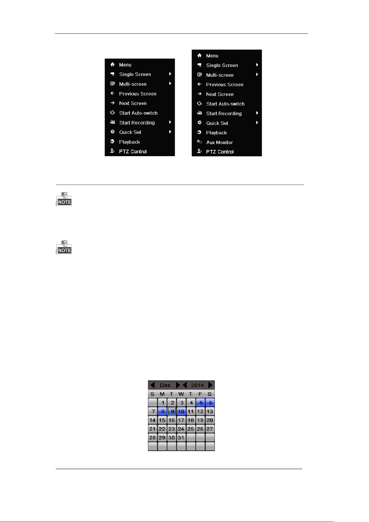
User Manual of Digital Video Recorder
DS-7100 and DS-7200 Other Models
Figure 6. 2 Right-click Menu under Live View
The DS-7100, DS-7200, and DS-7324/7332HGHI-SH provide no Aux Monitor option.
Front Panel: press PLAY button to play back recording files of the channel under single-screen live view mode.
Under multi-screen live view mode, the recorded files of the top-left channel will be played back.
For the DS-7300/8100/9000, pressing numerical buttons will switch playback to the corresponding camera
during playback process.
Playback by Time
Purpose:
Play back video files recorded in specified time duration. Multi-channel simultaneous playback and channel
switch are supported.
Steps:
1. Enter playback interface.
Menu>Playback
2. Check the checkbox of channel(s) in the channel list and then double-click to select a date on the calendar.
Figure 6. 3 Playback Calendar
99
 Loading...